
Related Manuals for Alemite 7886-A5


Summary of Contents for Alemite 7886-A5
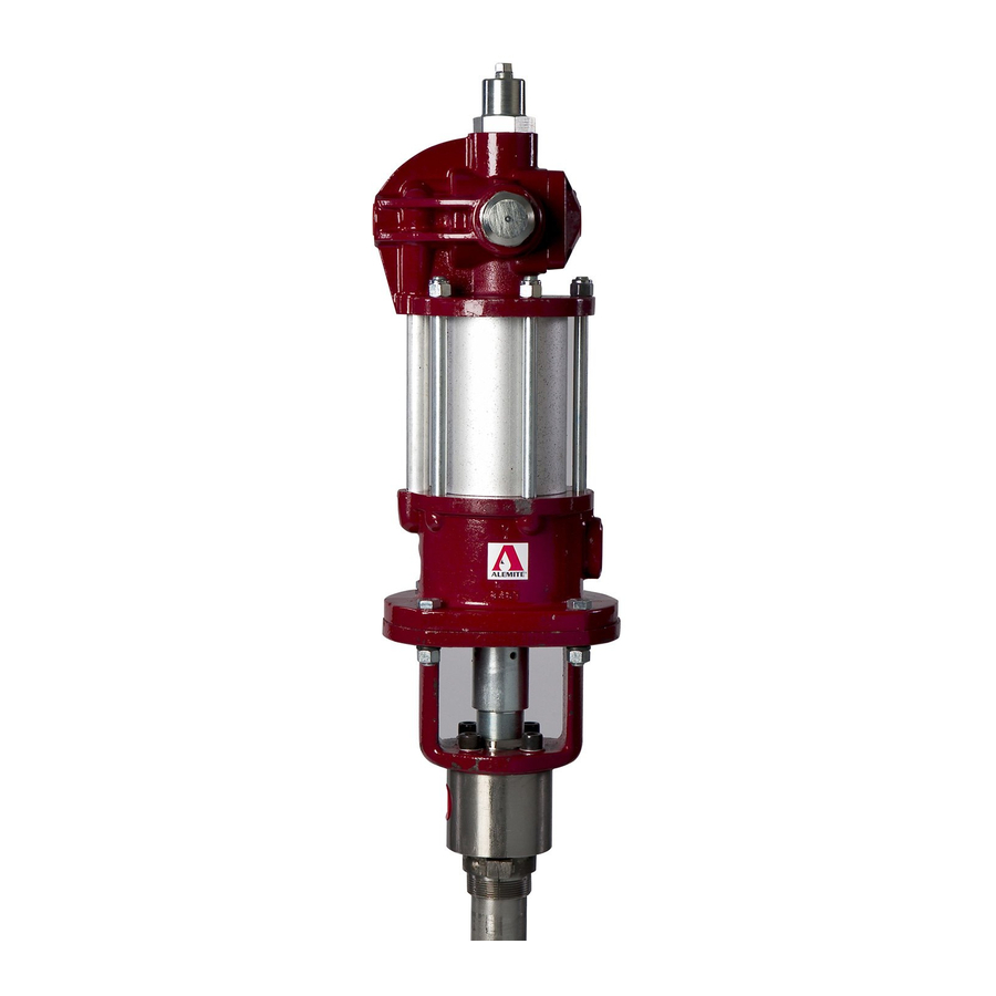
- Page 1 User and maintenance instructions Medium-pressure material pump Model 7886-A5 Date of issue October 2020 Form number 670752 Version...
-
Page 2: Table Of Contents
Contents Safety Description Air motor specifications Pump tube specifications Pump dimensions Accessories Hoists Pump performance Maintenance and repair Overhaul Disassembly Installation Service Service hints Service parts Repair kits Troubleshooting... -
Page 3: Safety
Safety Explanation of signal words for safety • Read and carefully observe these installation instructions before installing, operating or troubleshooting pump NOTE Pump must be installed, maintained and Emphasizes useful hints and repaired exclusively by persons familiar recommendations as well as with instructions information to prevent property damage •... -
Page 4: Description
Pump tube specifications original drums or bulk containers Material outlet 1 in NPTF Pump model 7886-A5 is designed with a Max material pressure 2 200 psi (152 bar) pump tube length to accommodate Max delivery... - Page 5 Fig. 1 Pump dimensions (1 590 mm) ∅ 2 in (51 mm) (825 mm) ∅ 2 (55 mm) Air inlet Air outlet Material inlet Material outlet...
-
Page 6: Pump Performance
Pump performance Pump’s ability to deliver material is based on pressure (psi/bars) and quantity (cfm/lpm) of air supplied to motor and amount of material discharge backpressure to be overcome within system Pump performance (page 6) contains curves based on three different air pres- sures Curves relate delivery in gallons (liters) per minute (X axis) to air consumption in cubic feet (liters) per minute (right Y axis) -
Page 7: Maintenance And Repair
Maintenance and repair Access to body packing Overhaul WARNING Prior to performing any maintenance, 8 Remove lower spring clip (2) that secures safety precautions must be observed rod (3) to coupling Failure to comply may lead to per- 9 Remove coupling from rod sonal injury 10 Remove packing screw (4) from plate (7) NOTE... - Page 8 Pump tube Clean and inspect NOTE Use appropriate Repair kits (page 17) 16 Unscrew valve body (39) from 1 Clean all metal parts in a modified petro- for replacement parts Make sure all cylinder (35) leum-based solvent Solvent should be components are included in kit before 17 Remove o-ring (34) from cylinder environmentally safe...
- Page 9 Piston packing Assembly 4 Install screw (19) into spacer and body Tighten screw securely Make sure 12 Clamp flats of guide (28) horizontally into spacer moves a soft-jaw vise 5 Position body small diameter upward 13 Install and seat spring (29) onto guide 6 Install and align upper mounting (8) 14 Position valve seat (32) with small diam- onto body...
- Page 10 Rods and cylinders Valve seat and guide assembly Valve body 24 Install o-rings (22) onto each end of 28 Install valve seat and guide assembly 32 Install ball (38) into top of valve extension cylinder (23) onto extension rod (25) until spring clip body (39) holes align 33 Install and seat washer (37) and stop...
- Page 11 Attach air motor to pump 7 Place a wood block onto surface of upper tube mounting († Fig. 3, page 8) 8 Position air motor assembly (41) onto 1 Extend rod (3) from top of body assembly pump tube assembly and block Make until it locks sure to orient air motor assembly properly...
- Page 12 With air pressure at zero: Bench test and 4 Slowly supply air pressure [not to exceed 15 psi (1 bar)] to pump’s motor Pump 11 Attach a control valve to outlet hose of operation assembly should begin to cycle If pump pump Make sure nozzle on control valve assembly does not cycle, loosen is open and pointed into an appropriate...
-
Page 13: Installation
Installation Table 6 Air line components Additional items that should be incorporated Part Description into air piping systems are listed in Air line components (page 13) 338862 Moisture separator/regulator and gauge combination 5608-3 Moisture separator 7608-B Regulator and gauge 5908-3 Lubricator 1) Air motor is lubricated at factory, life of motor can be extended with use of a lubricator... -
Page 14: Service
Service Service hints Settings effect efficiency of pump Refer to Overhaul (page 7) for details A Observe hole in packing screw (4) for oil overflow See Troubleshooting (page 20) for corrective measures B Fill cavity of packing screw (4) with oil to prevent product from drying on rod (25) C Loosen valve screw (13) prior to seal lubri- cation Damage to seals can occur... - Page 15 Fig. 5 Service hints...
- Page 16 Fig. IPB 1 Apply threadlocker Torque bar Point bleed hole downward Apply thread sealant * Indicates change...
-
Page 17: Service Parts
Service parts Item Description Part Quantity Item Description Part Quantity Coupling 323439 Extension rod Clip 324648 Stem 327653 330972 Stop 327646 Packing screw Guide Screw, in-20 × 1 Spring Lockwasher, Ring, male Plate Ring, female Upper mounting Valve seat 330301 Hydraulic fitting 1627-B Valve... - Page 18 Fig. 6 Repair kit 393003 Repair kit 393003 Item Description Part Quantity Item Description Part Quantity Clip 324648 Ring, male 331007 Washer, 1 254 in 330974 Ring, female 331009 Ring, female (brass) 330704 1) Valve seat 330301 V-packing (Buna-N) 331185-24 Valve 327650 Screw,...
- Page 19 Fig. 7 Repair kit 331916 Repair kit 331916 Item Description Part Quantity Item Description Part Quantity Clip 324648 O-ring, 1 in ID × 1 in OD 171018-31 Washer, 1 254 in 330974 Ring, female 331009 Ring, female (brass) 330704 O-ring, 1 in ID ×...
-
Page 20: Troubleshooting
Troubleshooting Condition Possible cause Corrective action Pump does not cycle Packing screw (4) too tight Loosen packing screw (4) Air motor not operating properly Inspect air motor and rebuild or replace as necessary Pump tube jammed and/or contains loose Rebuild pump tube components Insufficient air pressure Increase air pressure... - Page 21 This page left intentionally blank...
- Page 22 This page left intentionally blank...
- Page 23 This page left intentionally blank...
- Page 24 ® SKF and Alemite are registered trademarks of the SKF Group © SKF Group 2020 The contents of this publication are the copyright of the publisher and may not be reproduced (even extracts) unless prior written permission is granted Every care has been taken to ensure the accuracy...
Need help?
Do you have a question about the 7886-A5 and is the answer not in the manual?
Questions and answers