
Related Manuals for Allen-Bradley 1788-EN2DNR


Summary of Contents for Allen-Bradley 1788-EN2DNR
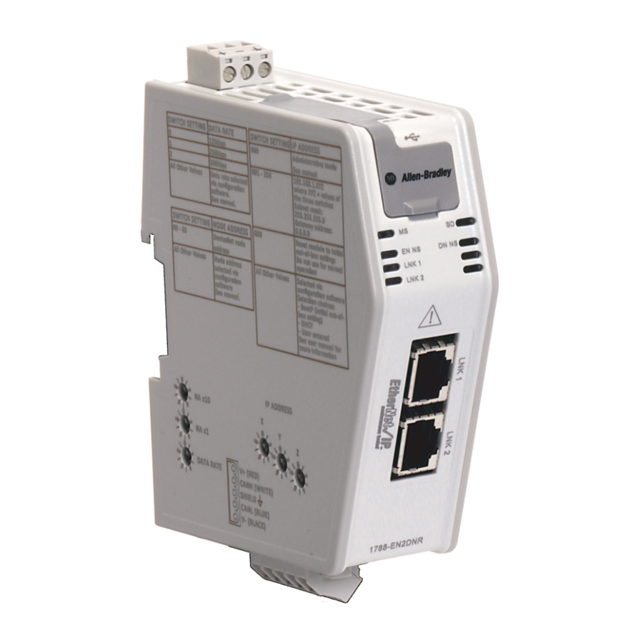
- Page 1 User Manual EtherNet/IP-to-DeviceNet Linking Device Catalog Numbers 1788-EN2DNR, 1788-EN2DNROM...
- Page 2 Regulatory requirements for safe work practices and for Personal Protective Equipment (PPE). Allen-Bradley, Rockwell Software, Studio 5000, Studio 5000 Logix Designer, Studio 5000 Automation Engineering & Design Environment, Logix5000, RSNetWorx, RSLinx, RSLogix, and Rockwell Automation are trademarks of Rockwell Automation, Inc.
- Page 3 Page Rewrote “About the Linking Device” section to reflect that there are two products presented in the manual. Added product picture for the 1788-EN2DNR and the 1788-EN2DNROM linking devices. Made two different “install” chapters, one for each linking device. Added introductory note for the “Configuring the Linking Device” chapter.
- Page 4 Summary of Changes Notes: Rockwell Automation Publication 1788-UM059B-EN-P - September 2015...
-
Page 5: Table Of Contents
DeviceNet Features......... . . 12 Mounting the 1788-EN2DNR Linking Device ..... 13 Mounting the 1788-EN2DNROM Linking Device. - Page 6 Network............34 Connect the 1788-EN2DNR Linking Device to the DeviceNet Network Set the DeviceNet Node Address and Baud Rate .
- Page 7 Table of Contents Chapter 6 SD Card Install or Remove the SD Card ........63 Load or Store to the SD Card .
- Page 8 Table of Contents Notes: Rockwell Automation Publication 1788-UM059B-EN-P - August 2015...
-
Page 9: Additional Resources
Provides declarations of conformity, certificates, and other certification details. You can view or download publications at http:/www.rockwellautomation.com/literature/. To order paper copies of technical documentation, contact your local Allen-Bradley distributor or Rockwell Automation sales representative. Rockwell Automation Publication 1788-UM059B-EN-P - September 2015... - Page 10 Preface Notes: Rockwell Automation Publication 1788-UM059B-EN-P - September 2015...
-
Page 11: About The Linking Device
The EtherNet/IP-to-DeviceNet linking device comes in two designs, the IP20 About the Linking Device linking device (catalog number 1788-EN2DNR) and the IP67 linking device (catalog number 1788-EN2DNROM). These devices let you seamlessly connect your information or control-level networks with your device-level network. -
Page 12: 1788-En2Dnr And 1788-En2Dnrom Linking Device Features
Chapter 1 Linking Device Overview The linking devices have these features. 1788-EN2DNR and 1788-EN2DNROM Linking 1788-EN2DNROM (IP67) 1788-EN2DNR (IP20) Device Features Features For Class 0 CIP Safety connections, 5 ms maximum delay from network to network EtherNet/IP Features • The linking device supports these connections: –... -
Page 13: Mounting The 1788-En2Dnr Linking Device
Linking Device Overview Chapter 1 The 1788-EN2DNR linking device can be mounted to a DIN rail. Mounting the 1788-EN2DNR Linking Device Mounting the Two mounting holes are used to mount the 1788-EN2DNROM linking device directly to a panel or machine. The mounting holes accommodate #8 (M4) pan 1788-EN2DNROM Linking head screws. -
Page 14: Devicenet Standard And Safety I/O
Chapter 1 Linking Device Overview The linking devices feature the possibility to bridge CIP safety messages. The DeviceNet Standard and linking devices support 32 CIP safety connections, with a maximum internal Safety I/O delay of 5 ms. Add I/O Online (Online The Online Scanlist Changes Allowed in Run (OSCAR) feature lets you manipulate the DeviceNet scanner configuration while the scanner is in Run Scanlist Changes Allowed in... -
Page 15: Environmental And Enclosure
Chapter Install the 1788-EN2DNROM Linking Device ATTENTION: Power to this equipment must be supplied from a source compliant with the following: • SELV source approved to IEC60950-1, IEC61010-2-201 or IEC62368-1 (ES1) • PELV source approved to IEC60950-1, IEC61010-2-201 or IEC62368-1 (ES1) If multiple power sources are used, do not exceed the specified isolation voltage. -
Page 16: Certifications
Chapter 2 Install the 1788-EN2DNROM Linking Device Certifications Certification (when product Value is marked) c-UL-us UL Listed Industrial Control Equipment, certified for US and Canada. See UL File E65584. European Union 2004/108/EC EMC Directive, compliant with: • EN 61000-6-4, Emission standard for industrial environment •... -
Page 17: System Requirements
Install the 1788-EN2DNROM Linking Device Chapter 2 The following hardware and software components are required to use the linking System Requirements device. Required Hardware • EtherNet/IP-to-DeviceNet linking device • DeviceNet cabling, power, and devices forming a DeviceNet network • Ethernet cabling •... -
Page 18: Connect The 1788-En2Dnrom Linking Device To The Devicenet Network
Chapter 2 Install the 1788-EN2DNROM Linking Device 1. With power to the linking device off, connect the DeviceNet network Connect the cable to the mini-style DeviceNet connector on the linking device. 1788-EN2DNROM Linking Male 7/8 in. (22 mm) Female 7/8 in. (22 mm) Device to the DeviceNet Network Pin 1 Bare (Shield) -
Page 19: Set The Devicenet Node Address And Baud Rate
Install the 1788-EN2DNROM Linking Device Chapter 2 Two methods can be used to set the DeviceNet node address and the baud rate: Set the DeviceNet Node • Use the node address and baud rate rotary switches on the linking device Address and Baud Rate •... -
Page 20: Set The Linking Device Ip Address By Using The Rotary Switches
Chapter 2 Install the 1788-EN2DNROM Linking Device Set the Linking Device IP Address by Using the Rotary Switches Set the IP address using the IP address switches, according to this table. Switch IP Address Administrative mode The linking device uses the IP address that was used last startup The web pages are available 001 - 254 192.168.1.XYZ where XYZ is the value of the three switches... -
Page 21: Set The Linking Device Ip Address By Using Dhcp/Bootp
Install the 1788-EN2DNROM Linking Device Chapter 2 Set the Linking Device IP Address by Using DHCP/BOOTP The use of DHCP is the default configuration for the linking device as shipped. When DHCP/BOOTP is enabled and a DHCP or BOOTP server is found, the IP address, subnet mask, and gateway address are automatically configured by the DHCP server, as shown in the following figure. - Page 22 Chapter 2 Install the 1788-EN2DNROM Linking Device The following figure shows a flowchart describing how the IP configuration is determined when the linking device is powered up. IP Configuration Flowchart Start Rotary Switches = 888? Factory Reset to DHCP Rotary Switches = 000? LED Indication Admin Mode...
-
Page 23: Set The Linking Device Ip Address By Using Rslinx Software
Install the 1788-EN2DNROM Linking Device Chapter 2 Set the Linking Device IP Address by Using RSLinx Software To use RSLinx software to set the IP address of the linking device, follow these steps. 1. Connect to the linking device using a USB cable. 2. -
Page 24: Web Pages
Chapter 2 Install the 1788-EN2DNROM Linking Device 8. Configure the port settings. Then Use the default port speed and duplex Leave Auto-negotiate port speed and duplex checked. settings This setting determines the actual speed and duplex setting. Manually configure your port’s speed Follow these steps. - Page 25 Install the 1788-EN2DNROM Linking Device Chapter 2 The IP address can be set with the web page only if the linking device already has a valid IP address. One way that you can do this is by using the rotary switch to force the linking device to use the IP address from the switches after you cycle power.
-
Page 26: Configure The Driver In Rslinx Software
Chapter 2 Install the 1788-EN2DNROM Linking Device 5. Click OK. The Network Configuration dialog box appears. 6. In the Network Configuration dialog box, enter the following values. Description Type IP Address Any valid value. See your system administrator for a valid IP address. -
Page 27: Register The Eds File
Install the 1788-EN2DNROM Linking Device Chapter 2 The EDS file for the linking device is accessible and downloadable with RSLinx Register the EDS File software. To register the EDS file in RSLinx software, follow these steps. 1. In RSLinx software, right-click the linking device. 2. - Page 28 Chapter 2 Install the 1788-EN2DNROM Linking Device Notes: Rockwell Automation Publication 1788-UM059B-EN-P - September 2015...
-
Page 29: Environmental And Enclosure
Chapter Install the 1788-EN2DNR Linking Device ATTENTION: • Read this document and the documents listed in the Additional Resources section about installation, configuration, and operation of this equipment before you install, configure, operate, or maintain this product. Users are required to familiarize themselves with installation and wiring instructions in addition to requirements of all applicable codes, laws, and standards. -
Page 30: European Hazardous Location Approval
Chapter 3 Install the 1788-EN2DNR Linking Device European Hazardous Location Approval ATTENTION: • Are Equipment Group II, Equipment Category 3, and comply with the Essential Health and Safety Requirements relating to the design and construction of such equipment given in Annex II to Directive 94/9/EC. See the EC Declaration of Conformity at http://www.rockwellautomation.com/products/certification for details. -
Page 31: Certifications
Install the 1788-EN2DNR Linking Device Chapter 3 Certifications Certification (when product Value is marked) c-UL-us UL Listed for Class I, Division 2 Group A,B,C,D Hazardous Locations, certified for U.S. and Canada. See UL File E194810. European Union 2004/108/EC EMC Directive, compliant with: •... -
Page 32: Specifications
Chapter 3 Install the 1788-EN2DNR Linking Device Specifications Attribute 1788-EN2DNR Temperature, operating -25…60 °C (-13…140 °F) • IEC 60068-2-1 (Test Ad, Operating Cold) • IEC 60068-2-2 (Test Bd, Operating Dry Heat) • IEC 60068-2-14 (Test Nb, Operating Thermal Shock) Temperature, nonoperating -40…85 °C (-40…185 °F) -
Page 33: System Requirements
Install the 1788-EN2DNR Linking Device Chapter 3 The following hardware and software components are required to use the linking System Requirements device. Required Hardware • EtherNet/IP-to-DeviceNet linking device • DeviceNet cabling, power, and devices forming a DeviceNet network • Ethernet cabling •... -
Page 34: Network
Chapter 3 Install the 1788-EN2DNR Linking Device Connect the EtherNet/IP network cable to either of the two RJ45 ports on the Connect the 1788-EN2DNR front of the linking device. Linking Device to the EtherNet/IP Network RJ45 Ports Rockwell Automation Publication 1788-UM059B-EN-P - September 2015... -
Page 35: Connect The 1788-En2Dnr Linking Device To The Devicenet Network
Install the 1788-EN2DNR Linking Device Chapter 3 Connect the 1788-EN2DNR ATTENTION: Power to this equipment must be supplied from a source compliant with the following: Linking Device to the • Class 2 approved to UL1310 DeviceNet Network • Limited Voltage Limited Current Supply compliant with UL508 •... -
Page 36: Set The Devicenet Node Address And Baud Rate
Chapter 3 Install the 1788-EN2DNR Linking Device Two methods can be used to set the DeviceNet node address and the baud rate: Set the DeviceNet Node • Use the node address and baud rate rotary switches on the linking device Address and Baud Rate •... -
Page 37: Set The Linking Device Ip Address By Using The Rotary Switches
Install the 1788-EN2DNR Linking Device Chapter 3 Set the Linking Device IP Address by Using the Rotary Switches Set the IP address using the IP address switches, according to this table. Switch IP Address Administrative mode The linking device uses the IP address that was used last startup... -
Page 38: Set The Linking Device Ip Address By Using Dhcp/Bootp
Chapter 3 Install the 1788-EN2DNR Linking Device Set the Linking Device IP Address by Using DHCP/BOOTP The use of DHCP is the default configuration for the linking device as shipped. When DHCP/BOOTP is enabled and a DHCP or BOOTP server is found, the IP address, subnet mask, and gateway address are automatically configured by the DHCP server, as shown in the following figure. - Page 39 Install the 1788-EN2DNR Linking Device Chapter 3 The following figure shows a flowchart describing how the IP configuration is determined when the linking device is powered up. IP Configuration Flowchart Start Rotary Switches = 888? Factory Reset to DHCP Rotary...
-
Page 40: Set The Linking Device Ip Address By Using Rslinx Software
Chapter 3 Install the 1788-EN2DNR Linking Device Set the Linking Device IP Address by Using RSLinx Software To use RSLinx software to set the IP address of the linking device, follow these steps. 1. Connect to the linking device using a USB cable. -
Page 41: Web Pages
Install the 1788-EN2DNR Linking Device Chapter 3 8. Configure the port settings. Then Use the default port speed and duplex Leave Auto-negotiate port speed and duplex checked. settings This setting determines the actual speed and duplex setting. Manually configure your port’s speed Follow these steps. - Page 42 Chapter 3 Install the 1788-EN2DNR Linking Device The IP address can be set with the web page only if the linking device already has a valid IP address. One way that you can do this is by using the rotary switch to force the linking device to use the IP address from the switches after you cycle power.
-
Page 43: Configure The Driver In Rslinx Software
Install the 1788-EN2DNR Linking Device Chapter 3 5. Click OK. The Network Configuration dialog box appears. 6. In the Network Configuration dialog box, enter the following values. Description Type IP Address Any valid value. See your system administrator for a valid IP address. -
Page 44: Register The Eds File
Chapter 3 Install the 1788-EN2DNR Linking Device The EDS file for the linking device is accessible and downloadable with RSLinx Register the EDS File software. To register the EDS file in RSLinx software, follow these steps. 1. In RSLinx software, right-click the linking device. -
Page 45: Rsnetworx For Devicenet Software
Chapter Configure the Linking Device The configuration information in this chapter applies to both the 1788- EN2DNR and the 1788-EN2DNROM linking devices. Remember to select the appropriate device in the configuration screens. 1. In RSNetWorx for DeviceNet software, choose Network > Online. RSNetWorx for DeviceNet 2. -
Page 46: Set The Devicenet Node Address And Baud Rate
Chapter 4 Configure the Linking Device Set the DeviceNet Node Address and Baud Rate To be able to set the node address and the baud rate from RSNetWorx for DeviceNet software, the rotary switches must be set to any value other than 0...63. - Page 47 Configure the Linking Device Chapter 4 4. In the left pane of the dialog box, click the + next to the IP address for the linking device. 5. In the left pane, click the + next to the DeviceNet network. You see the linking device in the left pane.
- Page 48 Chapter 4 Configure the Linking Device 10. Click Close. The linking device automatically restarts the DeviceNet network if a IMPORTANT new node address is entered. If the communication rate is changed, you must cycle power to the linking device before the new communication rate takes effect.
-
Page 49: Enable/Disable Autobaud
Configure the Linking Device Chapter 4 Enable/Disable Autobaud Autobaud is disabled by default. You can turn it on or off by following this procedure. 1. In RSNetWorx for DeviceNet software, click the linking device icon. 2. From the Device pull-down menu, choose Class Instance. 3. - Page 50 Chapter 4 Configure the Linking Device 6. Click Execute. A message in the ‘Data received from the device’ field indicates that the execution was completed. Changes to the autobaud option configuration do not take effect until IMPORTANT you cycle power to the linking device. You may also have to cycle power to the slave devices.
-
Page 51: Configure Devicenet I/O
Configure the Linking Device Chapter 4 Configure DeviceNet I/O Steps 8 and 9 are required only if the linking device is used as an I/O scanner. IMPORTANT The linking device can function as a gateway/bridge for explicit messaging and safety I/O routing, even if no I/O is configured. I/O Mapping The DeviceNet I/O configuration defines the format of the Input and Output tables, or the mapping of DeviceNet slaves’... - Page 52 Chapter 4 Configure the Linking Device 4. Double-click the linking device icon to open the Module Description dialog box. Several tabs appear on the top of the dialog box. 5. Click the Scanlist tab. 6. In the informational dialog box that appears, click Upload. The dialog box shows two columns.
- Page 53 Configure the Linking Device Chapter 4 The Input mapping dialog box appears. The top portion of this dialog box lists the devices in the scan list from which the linking device receives input data. The bottom shows the location in the Input table where the data is placed for each device.
-
Page 54: Studio 5000 Environment
Chapter 4 Configure the Linking Device These procedures explain how to work with the linking device in the Studio 5000 Environment Studio 5000® environment. Add the Linking Device to a Studio 5000 Logix Designer Application 1. In the Studio 5000 Logix Designer application, from the File menu, ®... - Page 55 Configure the Linking Device Chapter 4 7. From the Select Module Type dialog box, select “1788 Ethernet to DeviceNet Linking Device” and click Create. The AOP needs to be installed for the linking device to show up in the list. Download firmware and associated files (such as AOP files) from the Product Compatibility and Download Center at: http://...
- Page 56 Chapter 4 Configure the Linking Device 13. If an RSNetWorx for DeviceNet configuration file (filename *.dnt) already exists for the linking device, enter or browse to the appropriate filename. Doing so lets RSNetWorx for DeviceNet software launch directly from the Studio 5000 environment.
-
Page 57: Assembly Objects And Connections
Configure the Linking Device Chapter 4 Assembly Objects and Connections Three Assembly Object instances are accessible from the EtherNet/IP network: input, output and status. The input and output assemblies are linked to the input and output tags created in the Studio 5000 environment. The status assembly provides current status information about the linking device. - Page 58 Chapter 4 Configure the Linking Device Status Assembly The status assembly is a collection of status and diagnostic information for the linking device’s DeviceNet network interface. The information in the assembly is updated once a second. All information in the status assembly is stored in little endian format. The IMPORTANT least significant byte of multibyte values is stored first.
-
Page 59: Connect Via Usb To The Linking Device
3.0 m (9.84 ft) and must not contain hubs. WARNING: Do not use the USB port in hazardous locations. The USB port is located on the front of the linking device. The 1788-EN2DNR linking device has a regular USB port and the 1788-EN2DNROM linking device has a mini-B USB port. -
Page 60: Configure The Usb Driver
Chapter 5 USB Cable Configure the USB Driver To configure RSLinx software to use a USB port, you need to configure a USB driver. To configure a USB driver, perform this procedure. 1. Connect the linking device and your workstation by using a USB cable. The Found New Hardware Wizard appears. - Page 61 USB Cable Chapter 5 4. Click Finish to set up your USB driver. To browse to the linking device in RSLinx software, click the RSWho icon. The RSLinx Workstation organizer appears. The linking device appears under two drivers, a virtual chassis and the USB port.
- Page 62 Chapter 5 USB Cable Notes: Rockwell Automation Publication 1788-UM059B-EN-P - September 2015...
-
Page 63: Install Or Remove The Sd Card
Chapter SD Card The SD card option is available only for the 1788-EN2DNR linking device. Install or Remove the SD Card Complete these steps to install or remove the Secure Digital (SD) card in the linking device. WARNING: When you insert or remove the SD card while power is on, an electrical arc can occur. -
Page 64: Load Or Store To The Sd Card
Chapter 6 SD Card 2. Open the latch situated on the linking device and insert or remove the SD card. 3. Close the SD card latch. Using RSLogix 5000 software, the SD card can be used to load or store the Load or Store to the SD Card linking device’s configuration. -
Page 65: Load From The Sd Card
SD Card Chapter 6 Load from the SD Card To load the configuration currently on the SD card to the linking device, the inserted SD card can be either locked or unlocked. This image shows a locked SD card. Clicking Load to Module produces this warning. Clicking Yes loads the configuration stored on the SD card to the linking device. - Page 66 Chapter 6 SD Card Notes: Rockwell Automation Publication 1788-UM059B-EN-P - September 2015...
-
Page 67: Access The Diagnostic Web
Chapter Diagnostic Web Pages The diagnostic web pages are the same for the 1788-EN2DNR and the 1788- EN2DNROM linking devices. Access the Diagnostic Web To access the diagnostic web pages, do the following: Pages 1. Browse to the linking device by entering the IP address set by the switches in your web browser’s address bar and press Enter. -
Page 68: Idle Nodes
Chapter 7 Diagnostic Web Pages Idle Nodes The Idle Nodes page indicates which DeviceNet nodes are currently in the Idle state. If a node is Idle, the page displays ‘Idle’ next to the node’s MAC ID. Note that only nodes configured as slaves to the linking device and the linking device itself are updated on this page. - Page 69 Diagnostic Web Pages Chapter 7 Status Code Description Action Illegal data in scan list table Reconfigure the scan list table and remove any illegal data. Slave device stopped communicating Inspect the field devices and verify connections. Device’s identity information does not match Verify that the correct device is at this node electronic key in scan list table entry number.
- Page 70 Chapter 7 Diagnostic Web Pages Status Code Description Action Bus-off condition detected on comm port. Check DeviceNet connections and physical Module is detecting communication errors media integrity. Check system for failed slave devices or other possible sources of network interference. No network power detected on Provide network power.
-
Page 71: Diagnostic Web Pages-Ethernet
Diagnostic Web Pages Chapter 7 The following sections explain the diagnostic web pages for Ethernet. Diagnostic Web Pages— Ethernet Diagnostic Overview This overview contains general Ethernet information of the linking device: • CPU load • Number of TCP connections • Web server statistics •... -
Page 72: Ring Statistics
Chapter 7 Diagnostic Web Pages Media Counters Port 1/Port 2 Field Description Alignment Errors A frame containing bits that do not total an integral multiple of eight. FCS Errors A frame containing eight bits, at least one of which has been corrupted. Single Collisions The number of outgoing packets that encountered only one collision during transmission. -
Page 73: Linking Device
Appendix Status Indicators 1788-EN2DNROM 1788-EN2DNR Status Indicators Status Indicators Status Indicator Status Indicator Linking Device Indicator Status Description MS (EN2DR) Power off MOD (EN2DNROM) Green Normal operation (Module Status) Flashing green The module is not configured Unrecoverable error Flashing red... -
Page 74: Ethernet/Ip Network
Appendix A Status Indicators EtherNet/IP Network Indicator Status Description EN NS Power off, or no IP address (EtherNet/IP Status) Green Connected Flashing green Not connected Duplicate IP address Flashing red Connection timeout Alternating green/red Power-on self-test (POST) LNK 1, LNK 2 No link (Ethernet Link 1, 2) Flashing green... - Page 75 Index active nodes 67 faulted nodes 68 apply power to linking device 18 features assembly DeviceNet network 12 EtherNet/IP network 12 input 57 linking device 12 output 57 online scanlist changes allowed in Run mode status 58 Autobaud 49 safety I/O 14 cable, USB 59 hardware requirements 17 CIP safety...
- Page 76 Index DeviceNet data rate 19 mapping, I/O 51 DeviceNet node address 19 messages, CIP safety 14 IP address via RSLinx software 23 IP address via web pages 24 linking device IP address 19 software requirements 17 statistics, Ethernet 71 Network Configuration web page 24 status assembly 58 node address 19 status indicators 73...
- Page 78 Rockwell Automation Support Rockwell Automation provides technical information on the Web to assist you in using its products. http://www.rockwellautomation.com/support you can find technical and application notes, sample code, and links to software service packs. You can also visit our Support Center at https://rockwellautomation.custhelp.com/ for software updates, support chats and forums, technical information, FAQs, and to sign up for product notification updates.
Need help?
Do you have a question about the 1788-EN2DNR and is the answer not in the manual?
Questions and answers