Table of Contents
Advertisement
Advertisement
Table of Contents

Related Manuals for Allen-Bradley PicoTM Controller 1760


Summary of Contents for Allen-Bradley PicoTM Controller 1760
- Page 1 Pico™ Controller Bulletin 1760 Getting Results...
-
Page 2: Important User Information
Important User Information Solid state equipment has operational characteristics differing from those of electromechanical equipment. Safety Guidelines for the Application, Installation and Maintenance of Solid State Controls (Publication SGI-1.1 available from your local Rockwell Automation sales office or online at http://www.ab.com/manuals/gi) describes some important differences between solid state equipment and hard-wired electromechanical devices. -
Page 3: Table Of Contents
Preface Pico Controller Drawing a Circuit with Pico Pico Interface Socket Specifications Who Should Use this Manual....Preface-i Purpose of This Manual..... . . Preface-ii Common Techniques Used in this Manual . - Page 4 Table of Contents Publication 1760-GR001C-EN-P - April 2005...
-
Page 5: Who Should Use This Manual
Who Should Use this Manual Read this preface to familiarize yourself with the rest of the manual. It provides information concerning: • who should use this manual • the purpose of this manual • related documentation • conventions used in this manual •... -
Page 6: Purpose Of This Manual
Preface Purpose of This Manual A more detailed description of how to install and use your Pico controller. In-depth information on grounding and wiring Allen-Bradley programmable controllers A description of important differences between solid-state programmable controller products and hard-wired electromechanical devices An article on wire sizes and types for grounding electrical equipment A complete listing of current documentation, including ordering... -
Page 7: Rockwell Automation Support
Rockwell Automation Support Rockwell Automation offers support services worldwide, with over 75 Sales/Support Offices, 512 authorized Distributors and 260 authorized Systems Integrators located throughout the United States alone, plus Rockwell Automation representatives in every major country in the world. Local Product Support Contact your local Rockwell Automation representative for: •... - Page 8 Preface Publication 1760-GR001C-EN-P - April 2005...
-
Page 9: Chapter 1 Safety Information
Safety Information Simply Pico Pico Controller Electrical Shock Hazard ATTENTION The electrical installation and commissioning work must only be carried out by suitably qualified personnel. Do not work on the device when the power is turned Observe the relevant safety regulations: •... - Page 10 Pico Controller Publication 1760-GR001C-EN-P - April 2005 Applications Everywhere • Building and domestic automation, controllers for lighting, doors, window shutters • Control ventilators, rotating doors, greenhouses, exterior lighting, window controllers, shop display lighting • Create controllers for temperature, ventilation and brightness levels •...
-
Page 11: Mount Pico
Mount Pico Mount on DIN Rail 1. Hook Pico to the top edge of the DIN rail and rotate into place while pressing down slightly as shown by the arrow. 2. Pico will clip into place and is secured by the built-in spring mechanism. -
Page 12: Connect Pico
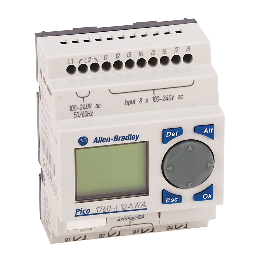
Pico Controller Connect Pico Publication 1760-GR001C-EN-P - April 2005 Pico Inputs1760-L12BBB-xx, 1760-L12BWB-xx and 1760-L12DWD-xx BWB: +24 V DWD: +12 V > 1 A BWB: = 24 V (20.4 - 28.8 V) = 80 mA 5 - 7 lb-in 3.5 mm DWD: = 12 V (10.2 - 15.6 V) - Page 13 Pico Outputs 1760-L12AWA-xx, 1760-L12BWB-xx, 1760-L12DWD-xx, 1760-L12BBB-xx and 1760-L12NWA-xx 10 000 000 8 A / B 16 L1, L2, L3 (120/240 V ) + 24 V Pico Inputs 1760-L18BWB-EX and 1760-L18BWB-EXND I1–I6, I9–I12 = 3.3 mA 28.8 V 24 V 1 ≥ 15 V I7, I8 = 2.2 mA 0 ≤...
- Page 14 Pico Controller Publication 1760-GR001C-EN-P - April 2005 Pico Inputs 1760-L18AWA-xx and 1760-L18NWA-xx 1 > 79 V 0 < 40 V > 1 A U e = 120/240 V 50/60 Hz (85–264 V) l e = 70 mA 120 V 35 mA 240 V 5-7 lb-in.
- Page 15 Pico Outputs 1760-L20xxx +24 V F 10 A 0 V H f 2.5 A + 24 V H (20.4 – 28.8 V H) Pico Inputs 1760-IB12XOB8 R1–R12 = 3.3 mA; 24 V 28.8 V 1 ≥ 15 V 0 ≤ 5 V +24 V >...
- Page 16 Pico Controller Publication 1760-GR001C-EN-P - April 2005 Pico Outputs 1760-IB12XOB8 S1 S2 S3 S4 0.5A 0.5A 5W/24V Pico Inputs 1760-IA12XOW6I and 1760-IB12XOW6I 10 000 000 < 8 A / B 16 L1, L2, L3 (120/240 V) + 24 V S5 S6 S7 S8 +24V dc COM ≤...
- Page 17 Pico Outputs 1760-IA12XOW6I and 1760-IB12XOW6I 10 000 000 < 8 A / B 16 L1, L2, L3 (120/240 V) + 24 V Pico Outputs 1760-OW8 Pico Controller 24 V 120 V 240 V 1000 W 10 x 58 W 25.000 Publication 1760-GR001C-EN-P - April 2005...
-
Page 18: Pico Operating Principle
1-10 Pico Controller Pico Operating Principle Publication 1760-GR001C-EN-P - April 2005 Pico Operating Buttons Button Function Delete object in the circuit diagram Special functions in the circuit diagram Cursor Move cursor Buttons Select menu item Choose contact numbers, values, times, etc. Next menu level, store your entry Previous menu level, cancel your entry... - Page 19 Move Through Menus to Choose Values Press Show system menu (press both keys at the same time). • Go to next menu level. • Select menu item. • Store your entry. Cancel your entry since the last Ok. E s c •...
-
Page 20: Menu Display
1-12 Pico Controller Publication 1760-GR001C-EN-P - April 2005 18-Point and 20-Point Status Display Inputs 1...5..8... Retention Enabled MO 02:00 ST Day, Time .2..5..8 Outputs Inputs 1, 5, 8 ON Outputs 2, 5, 8 ON Menu Display Current choice PROGRAM... blinks in the Pico RUN... -
Page 21: Cursor Display
Cursor Display There are two different cursor types: Full block navigation is shown as a flashing block: • Move cursor with the left/right arrows • When in circuit diagram, also use up/down arrows Parameter change cursor flashes the selected parameter: •... -
Page 22: Circuit Diagram Symbols
1-14 Pico Controller Publication 1760-GR001C-EN-P - April 2005 Circuit Diagram Symbols Cursor button as input Contact for input Contact for output Contact for internal marker bits Contact for timer relay Contact for counter relay Contact for real time clock switch Analog comparator contact Contact for text display (1) Contact for jump... -
Page 23: Menu Structure
Menu Structure PROGRAM... STOP RUN PARAMETER INFO... SET CLOCK PROGRAM... STOP RUN PARAMETER INFO... SET CLOCK PROGRAM... STOP RUN PARAMETER INFO... SET CLOCK PROGRAM... PARAMETER INFO... SET CLOCK PROGRAM... PARAMETER INFO... SET CLOCK Main Menu Without Optional Password Protection STOP: Circuit diagram menu RUN: Power flow display å... - Page 24 1-16 Pico Controller Publication 1760-GR001C-EN-P - April 2005 Main Menu Setting Summer Time PROGRAM... PARAMETER INFO... SET CLOCK SET CLOCK SUMMER TIME NONE RULE... SET CLOCK SUMMER TIME NONE RULE... SET CLOCK SUMMER TIME NONE RULE... SET CLOCK SUMMER TIME NONE RULE...
- Page 25 Main Menu with Password Protection Main Menu Unlock PASSWORD... Password PARAMETER INFO... SET CLOCK PASSWORD... If you do not know the password, you can delete the old password, but the circuit diagram and data will also be deleted. To delete the password, press Ok to DELETE ALL after entering four incorrect passwords.
-
Page 26: System Menu
1-18 Pico Controller System sECURITY... SYSTEM... LANGUAGE ... Change Password CONFIGURATOR SECURITY... SYSTEM... DEBOUNCE OFF P ON LANGUAGE... STOP MODE CONFIGURATOR SECURITY... SYSTEM... ENGLISH LANGUAGE... DEUTSCH CONFIGURATOR FRANCAIS ESPANOL ITALIANO PORTUGUES NEDERLANDS SVENSKA POLSKI TURKCE CESKY MAGYAR SECURITY... SYSTEM... LANGUAGE... CONFIGURATOR Publication 1760-GR001C-EN-P - April 2005 System Menu... -
Page 27: Chapter 2 Operation Of Pico
Operation of Pico Drawing a Circuit with Pico Buttons for Drawing Circuit Diagrams Button Function Delete branch, contact, relay, or empty rung in the circuit diagram Up/down arrows: Left/right arrows: E s c Chapter • Toggle between break and make contact •... -
Page 28: Set The Menu Language
Drawing a Circuit with Pico Set the Menu Language ENGLISH DEUTSCH FRANCAIS ESPANOL ITALIANO PORTUGUES NEDERLANDS SVENSKA POLSKI TURKCE CESKY MAGYAR Publication 1760-GR001C-EN-P - April 2005 Power Up Pico for the First Time A brief current surge is produced when powering on the unit for the first time. -
Page 29: Set The Time
Set the Time I 1 2 3 4 5 6 7 8 Q1234 12-I/O Pico Controllers with the “-NC” designation do not have real time clocks. Set the Real Time Clock 1 ...5 ..8 ... 02:00 14:15 .2 ..5 ..8 STOP 18-I/O Pico Set Week Day and Time... -
Page 30: Choose Pico Operating Mode
Drawing a Circuit with Pico Choose Pico Operating Mode Publication 1760-GR001C-EN-P - April 2005 Winter/Summer Time (Daylight Savings Time) SET CLOCK SUMMER TIME The two Pico operating modes are RUN and STOP. • RUN: Pico processes the circuit diagram. • STOP: Create and modify the circuit diagram. The alternating RUN/STOP menu shows either RUN or STOP as follows: •... -
Page 31: Pico Circuit Diagram Elements
Pico Circuit Diagram Elements Contacts Contacts are used to modify the flow of current in the circuit diagram. Contacts in the circuit diagram are either make or break contacts. Make contacts are open when off (de-energized) and closed when on. Break contacts are closed when off and open when on. - Page 32 Drawing a Circuit with Pico Relay type Controller Outputs Internal Marker Bits Internal Marker Bits Counters Timers Real Time Clock Operating Hours Counters Analog Setpoint Compare Text Display Jump to Label Expansion Outputs or Internal Marker Bits Year Time Switch Master Reset (1) Not available on “-NC”...
- Page 33 The options for setting output and marker relays are listed with the description of each coil function. Retentive Actual Values With Pico 1760-L12BWB-xx, 1760-L12DWD, and 1760-L18xxx, it is possible to save the actual values of markers, timers and counters in the event of a power failure.
- Page 34 Drawing a Circuit with Pico Publication 1760-GR001C-EN-P - April 2005 Basic Output Energize Instruction Output Maintained/Flip-Flop Output Instruction Output Latching Output Set Instruction Reset Instruction Output...
-
Page 35: Example: Creating A Circuit Diagram
Example: Creating a Circuit Diagram I 1 2 3 4 5 6 7 8 Q1234 12-I/O Pico Interconnect Contacts and Relays Pico circuit diagram I1-I2----{Q1 Draw Circuit in Circuit Diagram Menu Start Status Display 1 ...5 ..8 ... 02:00 14:15 .2 ..5 ..8 STOP 18-I/O Pico... - Page 36 2-10 Drawing a Circuit with Pico Publication 1760-GR001C-EN-P - April 2005 Insert Contact “I2” Draw Connection Between Contact and Relay Coil I1-I2 Choose Relay Coil “Q1” I1-I2--- I1-I2 I1-I2--- I1-I2--- I1-I2------{Q1 I1-I2------{Q1 I1-I2------{Q1...
-
Page 37: Change Operating Mode
Change Operating Mode I1-I1----{Q1 Pico now in RUN mode Test Circuit Diagram PROGRAM... STOP PARAMETER SET CLOCK... Drawing a Circuit with Pico PROGRAM DELETE PROG PROGRAM... PROGRAM... PARAMETER SET CLOCK.. PROGRAM... STOP PARAMETER SET CLOCK... Power flow display I1-I2----{Q1 Publication 1760-GR001C-EN-P - April 2005 2-11... - Page 38 2-12 Drawing a Circuit with Pico I1-I2----{Q1 In the next example, a timing relay will be added to the circuit. Publication 1760-GR001C-EN-P - April 2005 Operate Switch “S1” and “S2” “S1” on I1-I2----{Q1 “S2” on I1-I2----{Q1 Relay “Q1” picks up Return to Status Display with ESC I 1 2 3 4 5 6 7 8 Q1234...
-
Page 39: Function Relay Types
Function Relay Types Circuit Diagram Function Relay Type Symbol Timing relay with on-delay, with and without random switching Timing relay with off-delay, with and without random switching Timing relay, single pulse Timing relay, flashing Counter relay, up/down counter Time switch, weekday/time (only in Pico models with clock) Analog comparator relay (only in Pico models with 24V dc) Timing Relay Timing Relay with on delay, with and... - Page 40 2-14 Drawing a Circuit with Pico Publication 1760-GR001C-EN-P - April 2005 Timing Relay with Off-Delay, with and without Random Switching Trigger Reset Timer Output With random switching, the relay contact switches randomly at any time up to the specified time value (shown shaded in figure). Timing Relay, Single Pulse Trigger Reset...
- Page 41 Timing Relay, Flashing Flash Frequency = 1/2 x setpoint Trigger Reset Timer Output Parameter Display for Timing Relays Switch Function 00.00 Time Units 30.00 Trigger (Connected) Reset (Not Connected) Drawing a Circuit with Pico 2-15 Accumulated Time Setpoint Timer Number Parameter Display (Access Control) Publication 1760-GR001C-EN-P - April 2005...
- Page 42 2-16 Drawing a Circuit with Pico Publication 1760-GR001C-EN-P - April 2005 Counter Relay Count Input Direction Reset Accumulated Value (setpoint = 6) Counter Output Parameter Display for Counter Relays Counter Number C1 N AAAAA Setpoint Parameter Display (Access Control) Accumulated Value...
- Page 43 Real Time Switch Example: Real Time Switch 1 switches on Monday through Friday between 6:30 and 9:00 and again between 17:00 and 22:30 (5:00 pm and 10:30 pm). MO-FR 06:30 09:00 Parameter Display for Real Time Switches Real Time Switch Number Week Day(s) from - to On Time --:--...
-
Page 44: Analog Comparator
2-18 Drawing a Circuit with Pico Publication 1760-GR001C-EN-P - April 2005 Analog Comparator Available functions: • I7 ≥ I8, I7 ≤ I8 • I7 ≥ Setpoint, I7 ≤ Setpoint • I8 ≥ Setpoint, I8 ≤ Setpoint The analog comparator can compare voltages from 0V to 10V (setpoints “0.0”... -
Page 45: Text Display
Text Display The Text Display is used to display eight freely definable messages on the Pico screen. Each text block displays up to 48 characters from the Pico display character set (ASCII + Pico special characters). If the Text Display is enabled, the text entered via PicoSoft is displayed. If several Text Displays are enabled, the next screen is displayed every 4 seconds. -
Page 46: Example: Use A Function Relay
2-20 Drawing a Circuit with Pico Example: Use a Function Relay Publication 1760-GR001C-EN-P - April 2005 Conventional Circuit 10.0 sec Select an Internal Marker Relay Start Circuit from first example I1-I2----{Q1 Select Marker Contact and Connect to New Output Relay I1-I2----{M1 Pico switches M1 with 10 seconds delay. - Page 47 Select Trigger Relay for Time I1-I2----{M1 M1-------{Q1 Insert Timing Relay Contact I1-I2----{M1 M1-------TT1 Select Parameter Access I1-I2----{M1 M1-------TT1 Drawing a Circuit with Pico 2-21 I1-I2----{M1 M1-------TT1 I1-I2----{M1 M1-------TT1 I1-I2----{M1 M1-------TT1 I1-I2----{M1 M1-------TT1 00.00 Publication 1760-GR001C-EN-P - April 2005...
- Page 48 2-22 Drawing a Circuit with Pico Publication 1760-GR001C-EN-P - April 2005 Set “10 Seconds” 00.00 Connect Timing Relay Contact to New Output Relay I1-I2----{M1 M1-------TT1 Change Pico to RUN to test the program. Test the circuit as shown for the first example. To display and access the parameters for the timing relay and change the time value in RUN mode, position the cursor in the circuit diagram on the “T”...
-
Page 49: Basic Circuits
Basic Circuits Significance of Logic Values Value Function “0” Make contact open, break contact closed, relay coil not energized “1” Make contact closed, break contact open, relay coil energized Negation (NOR) Permanent Contact (Unconditional Rung) Flip-Flop Output State Q1 0 to 0 to Drawing a Circuit with Pico 2-23... - Page 50 2-24 Drawing a Circuit with Pico Publication 1760-GR001C-EN-P - April 2005 Series Connection (AND) Parallel Connection (OR) Exclusive OR Circuit (XOR) I1-I2-I3-{Q1 I1-I2-I3-{Q2 I1--------{Q1 I1--------{Q2 I1-I2------{Q1 I1-I2...
- Page 51 Motor Start/Stop Circuit Contact Coil Drawing a Circuit with Pico 2-25 I1--I2-----{Q1 Alternatively: I1--------SQ1 I2--------RQ1 Publication 1760-GR001C-EN-P - April 2005...
- Page 52 2-26 Drawing a Circuit with Pico Publication 1760-GR001C-EN-P - April 2005...
-
Page 53: Memory Module
Pico Interface Socket The Pico interface socket, which is beneath a protective cap, accepts the optional Pico memory module, or connects Pico to a PC using the optional PC interface cable and the PicoSoft software. This allows you to copy the circuit diagrams to and from the PC and/or memory module. - Page 54 Pico Interface Socket Publication 1760-GR001C-EN-P - April 2005 ELECTRICAL SHOCK HAZARD ATTENTION The memory module and PC-cable socket are at the potential of L2. There is a danger of electric shock if L2 is not grounded. Do not make contact with electrical components under the socket cover.
-
Page 55: Software Compatibility
PicoSoft PicoSoft is an optional PC program that creates, stores, and manages Pico circuit diagrams. It transfers the circuit diagrams from the PC to Pico or vice versa using a special PC interface cable. The PC interface cable is catalog number ATTENTION 1760-CBL-PM02 and is available as an accessory item. - Page 56 Pico Interface Socket Publication 1760-GR001C-EN-P - April 2005...
-
Page 57: Physical Specifications
Physical Specifications Specification Weight Ambient temperature, (operation) Storage Temperature Operating Humidity Emitted interference, interference immunity Standards and regulations Approvals Product Selection Table Catalog Number Inputs 1760-L12AWA 8 (120/240V ac) 1760-L12AWA-NC 1760-L12AWA-ND 1760-L18AWA 12 (120/240V ac) 1760-L18AWA-EX (2)(3) 1760-L18AWA-EXND Specifications 1760-L12xxx 1760-L18xxx, 1760-L20xx 1760-IA12XOW6I,... - Page 58 Specifications Catalog Number Inputs 1760-L12BWB 8 (24V dc) 1760-L12BWB-NC 1760-L12BWB-ND 1760-L12BBB 1760-L12BBB-ND 1760-L12NWA 8 (24V ac) 1760-L12NWA-ND 1760-L12DWD 8 (12V dc) 1760-L12DWD-ND 12 (24V dc) 1760-L18BWB-EX (2)(3) 1760-L18BWB-EXND 1760-L20BBB-EX (2)(3) 1760-L20BBB-EXND 12 (12V dc) 1760-L18DWD-EX (2)(3) 1760-L18DWD-EXND 12 (24V ac) 1760-L18NWA-EX (2)(3) 12 (24V ac)
-
Page 59: Expansion Modules
Accessories Catalog Number 1760-MM1 Memory Module for 12 I/O Pico Controller 1760-MM2 Memory Module for 18 I/O Pico Controller 1760-MM2B Memory Module for Pico Series B Controllers 1760-CBL-PM02 Programming Cable for Pico Controller 1760-RPLCONN Expansion Module Connector - included with expansion module. Catalog number listed is replacement part. 1760-SIM Input Simulator for 12 I/O 24V dc Pico Controller 1760-PICOSOFT... -
Page 60: Dimensions
Specifications Dimensions Publication 1760-GR001C-EN-P - April 2005 Pico 1760-L12xxx 10.75 50 1.97" 0.423" 35.75 1.41" 71.5 2.81" Pico 1760-L18xxx, 1760-L20xxx and Expansion Modules 16.25 75 2.96" 16.25 0.640" 0.640" 107.5 4.23" 4.5 0.177" 47.5 1.87" 56.5 2.22" 58 2.28" 4.5 0.177" 47.5 1.87"... - Page 61 Pico 1760-OW2 Expansion Module 7.5 0.295" 0.295" 35.5 1.4" Dimensions of the 1760-RM… Remote Processor modules 176-RM… 36.2 1.43" 22.5 30 1.18" 22.5 0.89" 0.89" 2.95" Specifications 1760-DU… and 176-RM… 20.5 43.2 1.7" 0.81" 27.5 1.08" Publication 1760-GR001C-EN-P - April 2005...
- Page 62 Specifications Publication 1760-GR001C-EN-P - April 2005...
-
Page 63: Index
accessories Allen-Bradley Preface-iii contacting for assistance Preface-iii support 2-18 Analog comparator Basic circuit 2-24 Exclusive OR circuit (XOR) 2-23 Flip-flop output 2-23 Impulse relay 2-25 Motor start/stop circuit 2-23 Negation (NOR) 2-23 Permanent contact 2-24 Series connection (AND) Break contact 1-10 Buttons Use in circuit diagrams... - Page 64 Index physical specifications Overview of Pico PicoSoft Programming cable publications, related Purpose of this Manual related publications Relay types Overview selection table controllers selections table expansion modules Setting the time Setting week day Software specifications physical Startup behavior Status display Summer time Publication 1760-GR001C-EN-P - April 2005 Preface-ii...
-
Page 66: Installation Assistance
Rockwell Automation Support Publication 1760-GR001C-EN-P - April 2005 Supersedes Publication 1760-GR001B-EN-P - July 2001 Rockwell Automation provides technical information on the web to assist you in using our products. At http://support.rockwellautomation.com, you can find technical manuals, a knowledge base of FAQs, technical and application notes, sample code and links to software service packs, and a MySupport feature that you can customize to make the best use of these tools.
Need help?
Do you have a question about the PicoTM Controller 1760 and is the answer not in the manual?
Questions and answers