Zamel RCR-01 Quick Manual
Radio motion sensor
Hide thumbs
Also See for RCR-01:
- Manual instruction (3 pages) ,
- Manual (33 pages) ,
- Manual instruction (3 pages)
Advertisement
BATTERY CHANGE
Battery discharge status is signalled by several LED red diode flashes during
transmission time.
1. Remove the upper cover
of the transmitter.
2. Remove the upper print-
ed-circuit board.
3. Remove the batteries.
4. Mount
new
batteries.
Watch battery polarisa-
tion marked on the latch.
Wrong battery mounting
may cause device dam-
age.
5. Mount the upper printed-circuit board inserting the pins into the connectors.
6. Mount the upper cover's latches into the latches of the base.
COOPERATION AND OPERATING RANGE
Symbol
ROP-01 ROP-02 ROB-01 SRP-02 SRP-03 RWG-01 RWL-01 ROМ-01 ROМ-10 RDP-01 RTN-01
RNK-02
180 м
200 м
200 м
200 м
RNK-04
180 м
200 м
200 м
200 м
P-256/8
230 м
250 м
250 м
250 м
P-257/4 (2)
180 м
200 м
200 м
200 м
RNМ-10
230 м
250 м
250 м
250 м
RNP-01
160 м
180 м
180 м
180 м
RNP-02
160 м
180 м
180 м
180 м
RNL-01
160 м
180 м
180 м
lack*
RTN-01
200 м
200 м
200 м
200 м
RCR-01
160 м
180 м
180 м
lack*
RTI-01
160 м
180 м
180 м
180 м
RXМ-01
230 м
250 м
250 м
250 м
* - 1-channel transmitters do not cooperate with roller blind controllers.
CAUTION: The given range concerns open area - an ideal condition without any
natural or artificial obstacles. If there are some obstacles between a transmitter
and a receiver, it is advisable to decrease the range according to: wood and plas-
ter: from 5 to 20 %, bricks: from 10 to 40 %, reinforced concrete: from 40 to 80 %,
metal: from 90 to 100%, glass: from 10 to 20 %, Over- and underground medium
and high electrical power lines, radio and television transmitters, GSM transmit-
ters set close to a device system have also a negative influence on the range.
200 м
250 м
180 м
250 м
250 м
200 м
250 м
180 м
250 м
250 м
250 м
300 м
200 м
300 м
300 м
200 м
250 м
180 м
250 м
250 м
250 м
300 м
200 м
300 м
300 м
180 м
200 м
160 м
200 м
200 м
180 м
200 м
160 м
200 м
200 м
lack*
200 м
160 м
200 м
200 м
200 м
250 м
200 м
250 м
250 м
lack*
200 м
160 м
200 м
200 м
180 м
200 м
160 м
200 м
200 м
250 м
300 м
200 м
300 м
300 м
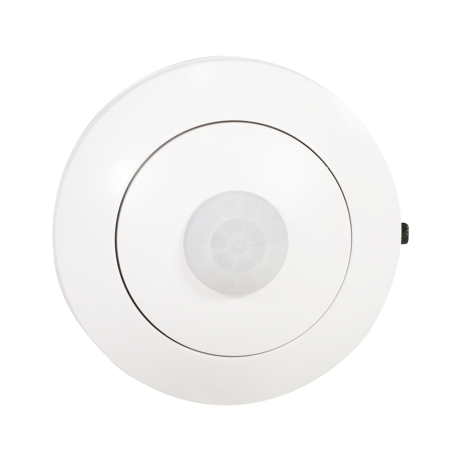
RADIO MOTION SENSOR
RCR-01
TECHNICAL DATA
Input rated voltage:
Battery type:
Battery life:
Liczba kanałów:
Twilight sensor adjustment range:
Transmission:
Coding way:
Coding:
Range:
Optic signalling of transmitter's operation: LED red diode
Ambient temperature range:
180 м
250 м
Operating position:
180 м
250 м
Casing mounting:
230 м
300 м
Casing protection degree:
180 м
250 м
Protection level:
230 м
300 м
160 м
200 м
Pollution degree:
160 м
200 м
Dimensions:
160 м
200 м
Weight:
200 м
250 м
Reference standard:
160 м
200 м
160 м
200 м
230 м
300 м
OPERATION
The device can operate in two modes: 1. Motion sensor, 2. Motion sensor with twilight
switch. Operation modes are adjusted by means of two switches which are under the
top cover of the sensor. Mode 1 - adjust the switch to „C" position, Mode 2 - adjust the
switch to „F" position. It is important to adjust the switches in the same position,
otherwise they operate incorrectly. In the operation mode with a twilight sensor
adjust luminous density by means of a potentiometer. Potentiometer adjustment to
„ " sign means operation adjustment during daylight - about 20 lx, and potentiometer
adjustment to „ " sign means operation adjustment during night - about 2 lx. Radio
transmission range (up to 200 m - depending on a receiver) can be increased by
means of a retransmitter or few RTN-01 retransmitters.
3 V DC
2 x AAA / R03
1 year (depending on use)
1
2 ÷ 20 lx
radio 868,32 MHz
unidirectional
addressing transmission
up to 200 m in the open area
-10 ÷ +55 °C
free
wall plugs, double-sided adhesive tape
IP20 (EN 60529)
III
2
Ø70 x 40 mm
0,070 kg
ETSI EN 300 220-1,
ETSI EN 300 220-2
Advertisement
Table of Contents

Related Manuals for Zamel RCR-01


Summary of Contents for Zamel RCR-01
- Page 1 RADIO MOTION SENSOR BATTERY CHANGE RCR-01 Battery discharge status is signalled by several LED red diode flashes during transmission time. 1. Remove the upper cover TECHNICAL DATA of the transmitter. 2. Remove the upper print- ed-circuit board. Input rated voltage: 3 V DC 3.
- Page 2 (first signal pulsates, next the signal is constant). Optic signalling range of operation Press PROG push-button of RCR-01 device and then release it. LED red diode in the re- PROG push-button ceiver switches on (signal pulsates), and then switches off - THE SENSOR IS ADDED.
Need help?
Do you have a question about the RCR-01 and is the answer not in the manual?
Questions and answers