Table of Contents
Advertisement
Quick Links
tel.: +48 32 210 46 65, +48 32 449 15 00, fax: +48 32 210 80 04
Do not dispose of this device with other waste! In order to avoid harmful effects on the
environment and human health, the used device should be stored in designated areas. For
this purpose, you can dispose of household waste free of charge and in any quantity to a
collection point set up, as well as to the shop when you buy new equipment.
Hereby, ZAMEL Sp. z o. o. declares that the radio equipment type RCR-21 is in compliance with
Directive 2014/53/EU. The full text of the EU declaration of conformity is available at the following
internet address: www.zamel.com
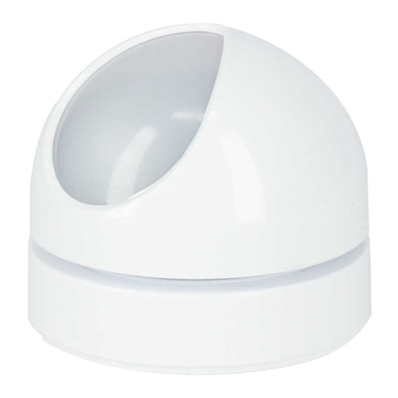
RADIO MOTION SENSOR
Zamel Sp. z o.o., ul. Zielona 27, 43-200 Pszczyna
e-mail: marketing@zamel.pl
RCR-21
www.zamel.com
Advertisement
Table of Contents

Subscribe to Our Youtube Channel
Summary of Contents for Zamel Exta Life RCR-21
- Page 1 Hereby, ZAMEL Sp. z o. o. declares that the radio equipment type RCR-21 is in compliance with Directive 2014/53/EU. The full text of the EU declaration of conformity is available at the following...
-
Page 2: Technical Data
TECHNICAL DATA DESCRIPTION RCR-21 sensor is designed to detect motion. Additionally, it has a built-in illuminance sensor 3.0 ÷ 3.6 V (internal ½ AA battery) Rated voltage: that controls the operation according to the intensity of sunlight. The sensor can work directly 6 ÷... - Page 3 SENSOR POWER SUPPLY - OPTIONS CONNECTING POWER TO THE PCL-21 CRADLE In the factory settings, RCR-21 is supplied with 3.6 V voltage from a single ½ AA battery. Alter- The PCL-21 cradle works correctly in the voltage range from 6 to 24 VAC/DC. Polarity (polarisa- natively, the device can be powered by batteries or an external voltage source 6 + 24 V AC/DC tion) of the connected voltage can be any.
- Page 4 ADDING SENSOR TO THE EFC-01 CONTROLLER APPEARANCE OF THE SENSOR IN THE APPLICATION 1. Switch on the EFC-01 controller and log in correctly to the mobile application EXTA LIFE. The RCR-21 sensor is visible in the application right after pairing. The sensor can be named indi- 2.
-
Page 5: Sensor Operation
SENSOR PARAMETRISATION the parameter “Accelerometer sensitivity” set from 1 to 3 with a step of 1, where 3 means the highest sensitivity. Change of configuration parameters is possible only for a sensor powered by an external voltage • Alarm reset - the button enables resetting the alarm related to activation of anti-tamper protec- source through the PCL-21 cradle. - Page 6 DELETING THE SENSOR FROM THE SYSTEM 3. DAY MODE • The sensor detects motion only when the illuminance level is higher than the set threshold. The When deleting the RCR-21 sensor from EXTA LIFE system, we may encounter three situations: threshold can be set within the range of 20 to 100,000 lx from the application level using the 1.
-
Page 7: Operating Mode Selection
OPERATING MODE SELECTION SENSOR PAIRING WITH SELECTED EXTA LIFE RECEIVERS Using the PROG button, the user can choose one of two modes of operation: 1. Press the PROG. button for a short time (0.5s) on the receiver.. 1. Work without light sensor (the motion sensor works all the time). 2. -
Page 8: Battery Replacement
BATTERY REPLACEMENT From the context menu, go to the screen ‘Version information’. The update starts after pressing the button ‘Update’. During the update, the sensor and the controller are switched to service fre- quency and control is not possible. Successful completion of the update is indicated by a message “Device successfully updated”. - Page 9 WORK WITH REP-21 RETRANSMITTER The sensor can work with a REP-21 retransmitter. This co-operation is required if problems are found in radio communication between the sensor and the controller. It is then recommended to install the REP-21 retransmitter between these devices. Co-operation between the sensor and the retransmitter can be implemented in two ways:: I.


Need help?
Do you have a question about the Exta Life RCR-21 and is the answer not in the manual?
Questions and answers