Table of Contents
Advertisement
Quick Links
Functional Safety Manual
SIL Safety Manual for
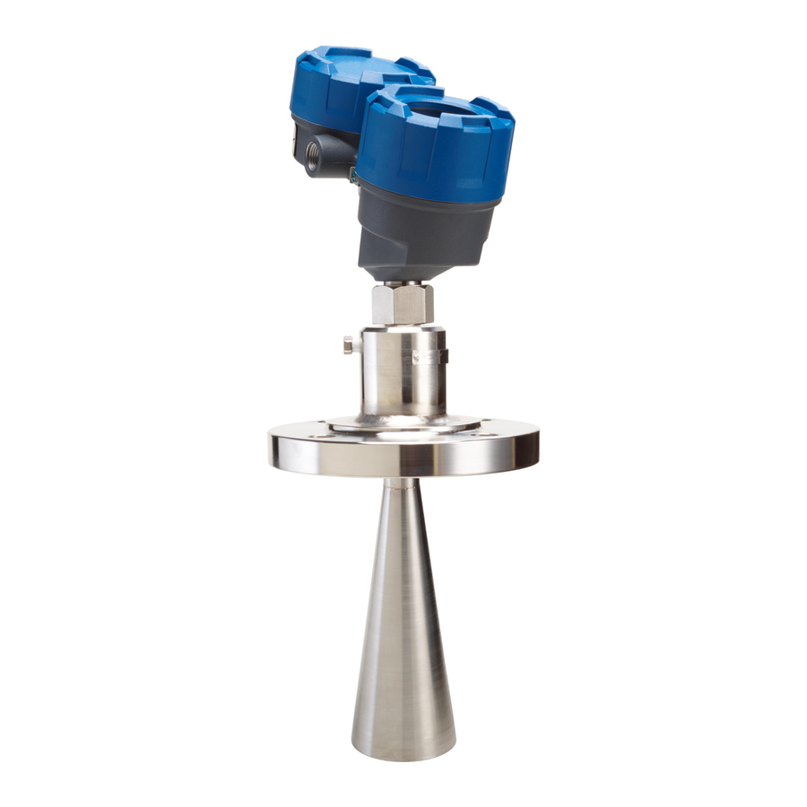
Pulsar Model R86
Model R86
26 GHz Pulse Burst Radar
Level Transmitter
This manual complements and is intended to be used with
®
the Pulsar
Model R86 Installation and Operating manual
(Bulletin 58-603).
Benefits
The PULSAR Model R86 (HART
transmitter can be applied in most indoor and outdoor
process or storage vessels. The PULSAR Model R86 can
be used in liquids or slurries to meet the safety system
requirements of IEC 61508/IEC 61511-1.
Benefits
The Magnetrol
Model R86 (HART) transmitter pro-
®
vides the following benefits to your operation:
• Protection up to SIL2 as independently assessed
(hardware assessment) by exida as per IEC 61508/
IEC 61511-1. Safe Failure Fraction:
•
93.2% (intrinsically safe)
•
93.0% (explosion-proof )
• Antenna designs to +750 °F (+400 °C),
2320 psig (160 bar)
• IS, XP and Non-Incendive approvals
• Quick connect / disconnect antenna coupling
• Performance not process dependent (changing specific
gravity and dielectric have no effect).
Software v1.x
) Pulse Burst level
®
Advertisement
Table of Contents

Subscribe to Our Youtube Channel
Related Manuals for Magnetrol PULSAR RADAR R86


Summary of Contents for Magnetrol PULSAR RADAR R86
- Page 1 The PULSAR Model R86 can be used in liquids or slurries to meet the safety system requirements of IEC 61508/IEC 61511-1. Benefits The Magnetrol Model R86 (HART) transmitter pro- ® vides the following benefits to your operation: •...
-
Page 2: Table Of Contents
Pulsar Model R86 Pulse Burst Radar Level Transmitter ® SIL 2 Suitable Table of Contents 1.0 Introduction ..............3 5.6 Configuration ............7 1.1 Product Description ..........3 5.6.1 General............7 1.2 Theory of Operation..........3 5.6.2 Write Protecting / Locking ......7 1.3 Determining Safety Integrity Level......3 5.6.3 Write Enabling / Unlocking ......8 2.0 Level Measuring System ..........4 5.7 Site Acceptance Testing ..........8... -
Page 3: Introduction
Introduction Product Description The Pulsar Model R86 Pulse Burst Radar Level ® Transmitter is a loop-powered, 24 VDC level transmitter Table 1 based on Pulse Burst Radar technology. For Safety Pulsar ® Model Number Instrumented Systems usage, it is assumed that the 4–20 mA output is used as the primary safety variable. -
Page 4: Level Measuring System
Unit The only unsafe mode is when the unit is reading an incor- rect level within the 4–20mA range (> ±2% deviation). MAGNETROL defines a safe failure as one in which the Pulsar ® Model R86 4–20 mA current is driven out of range (i.e., less than... -
Page 5: Overvoltage
2.2.2 Overvoltage The MAGNETROL Model R86 has over-voltage protection per CE requirements. When considering Hi-pot, Fast Transients and Surge, this protection is to 1000 volts. Therefore, there should be no unsafe failure modes up to 1 KV. Overvoltage Category II is a local level, covering appliances, portable equipment, etc., with smaller transient overvoltages... -
Page 6: Environmental
See Sections 2.3 & 2.4 of Installation and Operating Manual 58-603 for more detailed application information and limitations. 5.1.2 Environmental See Section 3.7 of Installation and Operating Manual 58-603 for environmental limitations. Skill Level of Personnel Personnel following the procedures of this safety manual should have technical expertise equal to or greater than that of a qualified instrument technician. -
Page 7: Installation
Logic Solver. Configuration 5.6.1 General The MAGNETROL PULSAR Model R86 can be config- ured via the local display, or via HART compatible hand- held terminal or personal computer. Ensure the parameters have been properly configured for the application. -
Page 8: Write Enabling / Unlocking
Diagnostic Failure. Worst-case internal fault detection time is one minute. 5.9.2 Troubleshooting Report all failures to MAGNETROL. Refer to Section 3.4 of the PULSAR Model R86 Installation and Operating Manual Bulletin 58-603 for troubleshooting device errors. -
Page 9: Recurrent Function Tests
Recurrent Function Tests Proof Testing 6.1.1 Introduction Following are the procedures utilized to detect Dangerous Undetected (DU) failures. The procedure will detect approximately 90% of possible DU failures in the Model R86. 6.1.2 Interval To maintain the Safety Integrity Level of a Safety Instrumented System, it is imperative that the entire system be tested at regular time intervals (referred to as TI in the appropriate standards). -
Page 10: Proof Test Procedure
6.1.4 Proof Test Procedure 1. Bypass the PLC or take other action to avoid a false trip. 2. Inspect the Unit in detail outside and inside for physical damage or evidence of environmental or process leaks. a. Inspect the exterior of the Unit housing. If there is any evidence of physical damage that may impact the integri- ty of the housing and the environmental protection, the unit should be repaired or replaced. - Page 11 i. This step tests for high quiescent current and supply voltage problems. ii. This also tests for current loop control circuitry and adjustment problems. c. Exit the “Analog Output Test” and confirm that the out- put returns to original state, with the proper loop current as indicated and controlled by the unit.
-
Page 12: Ppendices
ppendices FMED Report: Exida Management Summary 58-651 Pulsar ® Model R86 SIL Functional Safety Manual... - Page 13 58-651 Pulsar ® Model R86 SIL Functional Safety Manual...
-
Page 14: Sil Declaration Of Conformance
SIL Declaration of Conformity Hardware functional safety according to Section 2.4.4 of IEC 61508-2 (Edition 2.0: 2010). Magnetrol International, Incorporated 705 Enterprise Street, Aurora, Illinois 60504 declares as the manufacturer, that the level transmitter: Pulse Burst Radar (4-20 m ) Model R86-511x-xxx is suitable for use in safety-instrumented loops according to IEC 61508 on condition that “the good practice of... -
Page 15: Report- Lifetime Of Critical Components
Report: Lifetime of Critical Components According to section 7.4.9.5 of IEC 61508-2, a useful life- time, based on experience, should be assumed. Although a constant failure rate is assumed by the proba- bilistic estimation method, this only applies provided that the useful lifetime* of components is not exceeded. - Page 16 61511-1 Mod) – Informative” Disclaimer The SIL values in this document are based on an FMEDA analysis using exida’s SILVER Tool. MAGNETROL accepts no liability whatsoever for the use of these numbers of for the correctness of the standards on which the general calculation methods are based.
Need help?
Do you have a question about the PULSAR RADAR R86 and is the answer not in the manual?
Questions and answers