Table of Contents
Advertisement
Available languages
Available languages
Quick Links
Manuale d'uso
User manual
E1
Sistema radiocomando industriale
Industrial radio remote control
AT E1-MIA
Apparato trasmittente
Transmitting Unit
ELCA S.r.l.
MULTI man E1-MIA 00
Via del Commercio, 7/b - 36065 Mussolente (VI) ITALY
www.elcaradio.com tel. +39 0424 578500 fax +39 0424 578520
0408MA000160
Advertisement
Chapters
Table of Contents

Related Manuals for ELCA E1


Summary of Contents for ELCA E1
- Page 1 User manual Sistema radiocomando industriale Industrial radio remote control AT E1-MIA Apparato trasmittente Transmitting Unit ELCA S.r.l. Via del Commercio, 7/b - 36065 Mussolente (VI) ITALY www.elcaradio.com tel. +39 0424 578500 fax +39 0424 578520 MULTI man E1-MIA 00 0408MA000160...
- Page 3 Manuale d’uso User manual...
-
Page 5: Table Of Contents
ITA man E1-MIA 00 Sistema Radiocomando E1-MIA INDICE 1. MANUALE D’USO .............................. 2. ISTRUZIONI DI IMPIEGO ..........................2.1 INFORMAZIONI GENERALI ..........................2 2.2 APPLICAZIONI E CONDIZIONI DI UTILIZZO NON AMMESSI ............2 2.3 ISTRUZIONI PER UN USO CORRETTO E SICURO ................ - Page 6 ITA man E1-MIA 00 Sistema Radiocomando E1-MIA - Pagina II -...
-
Page 7: Manuale D'uso
Vostro lavoro. Questo manuale ed ogni eventuale allegato sono proprietà di ELCA e tutti i diritti sono riservati. Nessuna parte di questa pubblicazione può essere riprodotta o trasmessa in nessuna forma per nessun motivo senza il permesso scritto di ELCA. -
Page 8: Istruzioni Di Impiego
Schema a blocchi generale Il Sistema Radiocomando ELCA di Tipo E1 è una famiglia di radiocomandi industriali di sicurezza, utilizzabili per il comando di apparati di sollevamento, di trasporto ed in generale su macchine in cui siano richieste specifiche caratteristiche di sicurezza sull’avvio non voluto dei comandi in posizione di riposo (UMFS PL c) e sul comando di Stop (Cat. -
Page 9: Istruzioni Per Un Uso Corretto E Sicuro
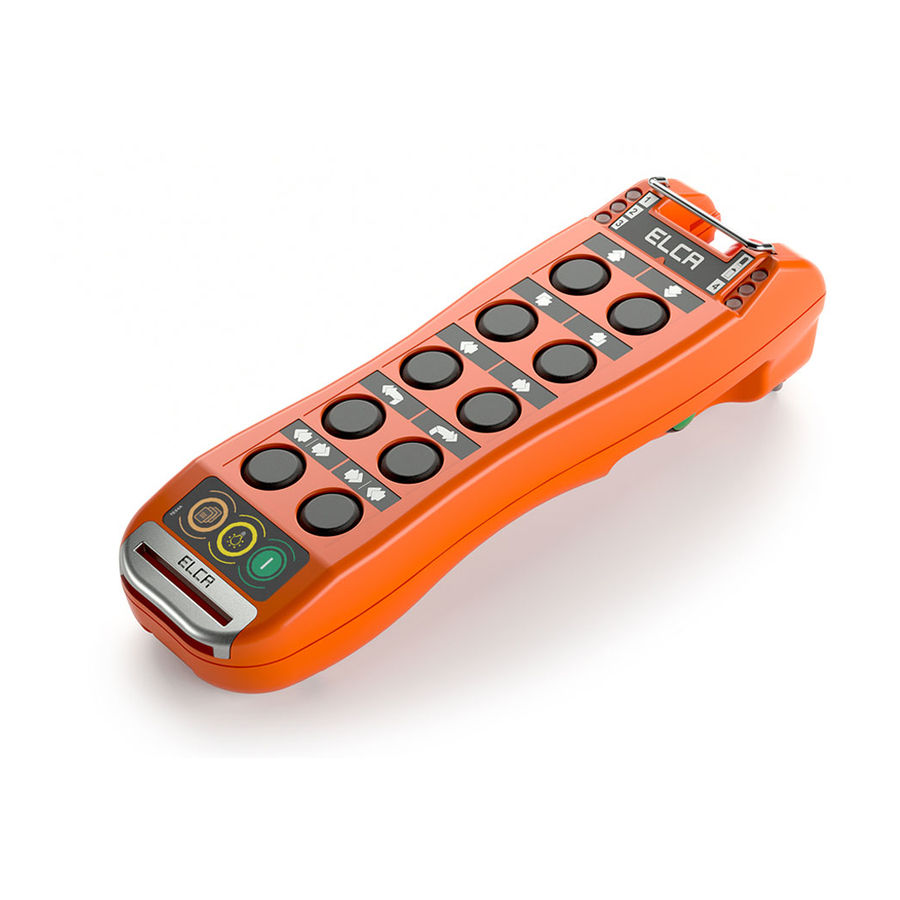
ITA man E1-MIA 00 Sistema Radiocomando E1-MIA 2.3 ISTRUZIONI PER UN USO CORRETTO E SICURO LED di controllo Dispositivi di comando Spie di controllo Dispositivi di comando Fungo di Stop Fungo Stop LED di controllo Spie di controllo UNITA’ UNITA’ TRASMITTENTE TRASMITTENTE UNITA’... - Page 10 ITA man E1-MIA 00 Sistema Radiocomando E1-MIA Utilizzare cavi di sezione idonea max. 2,5 mmq. Collegare il circuito di Stop facendo attenzione che la corrente in esso circolante non superi il valore del fusibile di protezione. Distribuire il comune alle funzioni interponendo sempre il relè di Safety.
-
Page 11: Funzionalita' Programmabili
2.4 FUNZIONALITA’ PROGRAMMABILI Il sistema radiocomando E1 permette la programmazione da parte dell’utente di alcune sue funzionalità fra cui: - ATTIVAZIONE SEQUENZA DI ABILITAZIONE PREDEFINITA - IMPOSTAZIONE SEQUENZA DI ABILITAZIONE PERSONALIZZATA - TEMPORIZZAZIONE DELL’AUTOSPEGNIMENTO... -
Page 12: Informazioni Per L'installazione
ITA man E1-MIA 00 Sistema Radiocomando E1-MIA 2.5 INFORMAZIONI PER L’INSTALLAZIONE L’installazione deve essere necessariamente eseguita da personale qualificato ed eventualmente abilitato come richiesto dalle disposizioni di legge di alcuni Stati L’installazione riveste una rilevantissima importanza, poiché da essa dipendono la sicurezza del macchinario, il buon funzionamento e la facilità... -
Page 13: Manutenzione
ITA man E1-MIA 00 Sistema Radiocomando E1-MIA 2.6 MANUTENZIONE Prima di procedere con qualsiasi tipo di operazione di manutenzione, assicurarsi che: - il ricevitore NON sia alimentato; - il trasmettitore sia spento - il fungo di STOP sia premuto. Nel caso in cui per le operazioni di manutenzione sia necessario intervenire sulla macchina o sull’unità ricevente: - scollegare elettricamente l’unità... -
Page 14: Garanzia
2.7 GARANZIA La durata del periodo di garanzia del Sistema Radiocomando ELCA tipo E1 è di 24 mesi a partire dalla data di acquisto, confermata dalla data del Documento Di Trasporto, nel quale deve essere presente il numero di matricola del Sistema Radiocomando interessato. -
Page 15: Dati Tecnici
ITA man E1-MIA 00 Sistema Radiocomando E1-MIA 3. DATI TECNICI 3.1 CARATTERISTICHE GENERALI CARATTERISTICHE GENERALI. Ditta costruttrice..............................ELCA S.r.l. Tipo sistema radiocomando ............................E1 Frequenza di lavoro ........................433,050 - 434,790 MHz Canalizzazione utilizzata ............................25 kHz Temperatura di lavoro ..........................da -25 °C a +55 °C Temperatura di stoccaggio e trasporto ....................da -25 °C a +55 °C... -
Page 16: Caratteristiche Sistema Di Ricarica
4. UNITA’ TRASMITTENTE 4.1 DESCRIZIONE DEL FUNZIONAMENTO L’unità trasmittente AT E1-MIA contiene al suo interno un codice identificativo univoco che permette all’unità ricevente l’identificazione certa dell’apparato che ha trasmesso il comando. In questo modo qualsiasi altro apparato, diverso o dello stesso tipo, che trasmetta sulla stessa frequenza non potrà in alcun caso sostituirsi al controllo della macchina a cui il sistema è... -
Page 17: Apparati Con Sistema Mts (Multi-Transmitter System)
4.2 APPARATI CON SISTEMA MTS (MULTI-TRANSMITTER SYSTEM) Gli apparati della serie E1 dotati di sistema MTS (Multi-Transmitter System) consentono a più trasmittenti E1-MIA di comandare la stessa unità ricevente. Tutti i trasmettitori che compongono il sistema, sono abilitati a comandare l’unità... -
Page 18: Unita' Ricevente
5. UNITA’ RICEVENTE 5.1 DESCRIZIONE DEL FUNZIONAMENTO L’unità ricevente AR E1 FEXI.A è costituito da quattro parti principali. SCHEDA BASE. Contiene i relè di STOP, SAFETY e di comando, i morsetti per il collegamento elettrico, lo stadio di alimentazione ed il supporto con il collegamento elettrico del modulo radio ricevente. - Page 19 ITA man E1-MIA 00 Sistema Radiocomando E1-MIA MODULO RADIO RICETRASMITTENTE SCHEDA CODICE IDENTIFICATIVO SCHEDA ESPANSIONE ESPANSIONE ESPANSIONE - Pagina 13 -...
-
Page 20: Esempio Di Cablaggio
ITA man E1-MIA 00 Sistema Radiocomando E1-MIA 5.2 ESEMPIO DI CABLAGGIO 0Vac SUPPLY 48/55/110/230Vac 110V SUPPLY 230V V= 10...55 Vac/dc - Pagina 14 -... -
Page 21: Caricabatterie
ITA man E1-MIA 00 Sistema Radiocomando E1-MIA 6. CARICABATTERIE 6.1 USO DEL CARICABATTERIE La ricarica dell’unità trasmittente deve essere effettuata in un ambiente la cui temperatura sia compresa fra 0°C e 40°C. Con temperature al di fuori di questo limite la ricarica non è permessa. -
Page 22: Sostituzione Dell'unita' Trasmittente
STOP. IMPORTANTE: rimuovere la targa dati dalla trasmittente non più utilizzabile ed applicarla sulla nuova. Nel caso non sia possibile perchè persa, distrutta o illeggibile, contattare un Centro Assistenza ELCA per richiederne il rifacimento. 7.2 SOSTITUZIONE SCHEDA CODICE DI ABBINAMENTO Per accedere alla scheda con il codice univoco di abbinamento è... -
Page 23: Procedura Di Acquisizione Codice Identificativo
ITA man E1-MIA 00 Sistema Radiocomando E1-MIA 7.3 PROCEDURA DI ACQUISIZIONE CODICE IDENTIFICATIVO Ogni apparato alla sostituzione della scheda con il codice di identifi cativo deve essere abilitato al suo utilizzo mediante la procedura di acquisizione del codice identifi cativo. -
Page 24: Ricerca Guasti
ITA man E1-MIA 00 Sistema Radiocomando E1-MIA 8. RICERCA GUASTI 8.1 TIPO DI INCONVENIENTE - COLLEGAMENTO RADIO ASSENTE: Premendo Start non si attiva il collegamento radio. Il collegamento radio è attivo e funzionante quando il LED verde lampeggia lentamente (1 lampeggio ogni secondo). -
Page 25: Verifica Funzionale Apparato Trasmittente
ITA man E1-MIA 00 Sistema Radiocomando E1-MIA 8.2 VERIFICA FUNZIONALE APPARATO TRASMITTENTE Seguire lo schema seguente partendo in alto a sinistra per risolvere o individuare l’inconveniente. FACENDO START FACENDO START ESEGUIRE RICARICA IL LED VERDE SI IL LED VERDE SI BATTERIA. -
Page 26: Verifica Funzionale Unita' Ricevente
ITA man E1-MIA 00 Sistema Radiocomando E1-MIA 8.3 VERIFICA FUNZIONALE UNITA’ RICEVENTE Seguire lo schema seguente partendo in alto a sinistra per risolvere o individuare l’inconveniente. VERIFICARE CHE IL CAVO DI ALIMENTAZIONE SIA IL RICEVITORE E' FORNIRE CORRETTAMENTE ALIMENTATO? ALIMENTAZIONE. -
Page 27: Verifica Funzionale Del Ciclo Di Carica
ITA man E1-MIA 00 Sistema Radiocomando E1-MIA 8.4 VERIFICA FUNZIONALE DEL CICLO DI CARICA Seguire lo schema seguente partendo in alto a sinistra per risolvere o individuare l’inconveniente. LED VERDE CICLO DI CARICA ACCESO? COMPLETATO LED ROSSO ACCESO? PULIRE I CONTATTI... - Page 28 ENG man E1-MIA 00 E1-MIA Radio Remote Control TABLE OF CONTENTS 1. USER MANUAL ................................2. USE INSTRUCTIONS ............................2.1 GENERAL INFORMATION ..........................2 2.2 APPLICATIONS AND USE CONDITIONS NOT PERMITTED ............... 2 2.3 INSTRUCTIONS FOR PROPER AND SAFE USE ..................
- Page 29 ENG man E1-MIA 00 E1-MIA Radio Remote Control - Page II -...
-
Page 30: User Manual
This manual and any annexed documents are the property of ELCA and all rights are reserved. No parts of this publication may be reproduced or transmitted in any form or by any means, without written permission from ELCA. -
Page 31: Use Instructions
General block diagram The E1 model ELCA Radio Remote Control System is a family of industrial safety radio remote controls that can be used for the control of lifting, transportation and general equipment on machines where specific safety features are required on the unintended activation of commands in the rest position (UMFS PL c) and the Stop command (PL d). -
Page 32: Instructions For Proper And Safe Use
ENG man E1-MIA 00 E1-MIA Radio Remote Control 2.3 INSTRUCTIONS FOR PROPER AND SAFE USE Control indicator LEDs Spie di controllo Command devices Dispositivi di comando Stop mushroom button Fungo Stop Control indicator LEDs Spie di controllo TRANSMITTING UNIT UNITA’ TRASMITTENTE RECEIVING UNIT UNITA’... - Page 33 ENG man E1-MIA 00 E1-MIA Radio Remote Control Connect the Stop circuit making sure that the current circulating therein does not exceed the value of the protection fuse. Distribute the common wire to the functions interposing always the Safety relay.
-
Page 34: Programmable Functions
ENG man E1-MIA 00 E1-MIA Radio Remote Control 2.4 PROGRAMMABLE FUNCTIONS The MAGO radio remote control system allows the user to program some of its functions including: - ACTIVATION/DEACTIVATION OF THE DEFAULT ENABLING SEQUENCE - SETTING OF THE PERSONALISED ENABLING SEQUENCE... -
Page 35: Information For Installation
ENG man E1-MIA 00 E1-MIA Radio Remote Control 2.5 INFORMATION FOR INSTALLATION The installation must be performed by qualified personnel and certified as required by law in some Countries. Installation is of considerable importance, since it depends on the safety of the machinery, its operation and the ease to perform effective maintenance on the radio remote control. -
Page 36: Maintenance
ENG man E1-MIA 00 E1-MIA Radio Remote Control 2.6 MAINTENANCE Before proceeding with any kind of maintenance operation, make sure that: - the receiver is NOT powered; - the transmitter is off - the mushroom STOP button is activated. In the event it is necessary to intervene on the machine or on the receiving unit for maintenance operations: - electrically disconnect the receiver unit from the machine. -
Page 37: Warranty
Warranty does not cover transport damage or loss. ELCA shall not be held liable for damage to property or persons. ELCA shall not be liable for machine down time, and it is the user's responsibility to provide manual or wire control for each machine. -
Page 38: Technical Data
3. TECHNICAL DATA 3.1 GENERAL FEATURES GENERAL FEATURES. Manufacturer ..............................ELCA S.r.l. Radio Remote Control System type ..........................E1 Working frequency ..........................433,050 - 434,790 MHz Channel spacing used ............................. 25 kHz Working temperature ........................from -25 °C to +55 °C Storage and transportation temperature....................from -25 °C to +55 °C Operating range................................. -
Page 39: Charging System Features
4.1 DESCRIPTION OF OPERATIONS The AT E1-MIA transmitting unit contains an internal identification code card that allows the receiving unit the identification of the unit that has transmitted the command. In this way any other device, different or the same type, that is transmitting on the same frequency can not in any way replace the control of the machine to which the system is connected. -
Page 40: Equipment With Mts System (Multi-Transmitter System)
4.2 EQUIPMENT WITH MTS SYSTEM (MULTI-TRANSMITTER SYSTEM) The devices of the series E1 with MTS (Multi-Transmitter System) enable multiple transmitters E1-MIA to command the same receiver. All transmitters that compose the system are enabled to control the receiver, but only one at a time exclusively and uniquely determined. -
Page 41: Receiving Unit
ENG man E1-MIA 00 E1-MIA Radio Remote Control 5. RECEIVING UNIT 5.1 DESCRIPTION OF OPERATIONS The receiving unit AR MAGO FEXI.A consists of three main parts. MOTHER BOARD. It contains the STOP, SAFETY and command relays, the terminals for the electrical connection, the power supply stage and support with the electrical connection of the radio receiving module. - Page 42 ENG man E1-MIA 00 E1-MIA Radio Remote Control RADIO RECEIVING MODULE IDENTIFICATION CODE CARD EXSPANSION CARD CARD CARD - Page 13 -...
-
Page 43: Wiring Example
ENG man E1-MIA 00 E1-MIA Radio Remote Control 5.2 WIRING EXAMPLE 0Vac SUPPLY 48/55/110/230Vac 110V SUPPLY 230V V= 10...55 Vac/dc - Page 14 -... -
Page 44: Battery Charger
ENG man E1-MIA 00 E1-MIA Radio Remote Control 6. BATTERY CHARGER 6.1 BATTERY CHARGER USAGE The transmitter must be recharged in an environment in which the temperature ranges between 0°C and 40°C. this will obtain maximum performance in terms of charging capacity and useful life of the battery. -
Page 45: Coupling Verification
IMPORTANT : the data label on the original transmitter should be removed and applied to the new transmitter. If this is not possible because it has been lost, destroyed, or illegible, please contact an ELCA Service Center to request a duplicate. -
Page 46: Cancellation (Erasing)
ENG man E1-MIA 00 E1-MIA Radio Remote Control 7.3 ENABLING IDENTIFICATION CODE CARD Any equipment replacing the card with the identifi cation code must be enabled for its use by the identifi cation code acquisition procedure. At the fi rst power on the transmitter, the red and green LEDs are lit up for 3 seconds at the same time, and then it remains awaiting command inputs with the green fl ashing light fl ashing slowly. -
Page 47: Troubleshooting
ENG man E1-MIA 00 E1-MIA Radio Remote Control 8. TROUBLESHOOTING 8.1 TYPE OF TROUBLE - RADIO CONNECTION FAILURE: The radio connection is not activated when Start is pressed. The radio connection is active and working when the green LED blinks slowly (1 flash every second). The lighting of the red blinking LED indicates low battery (1 hour remaining). -
Page 48: Transmitting Unit Functional Control
ENG man E1-MIA 00 E1-MIA Radio Remote Control 8.2 TRANSMITTING UNIT FUNCTIONAL CONTROL Follow the diagram below (starting from the top left corner) to solve or identify the problem. DOES THE GREEN RECHARGE DOES THE GREEN LED LED SWITCH ON BATTERY. -
Page 49: Receiving Unit Functional Control
ENG man E1-MIA 00 E1-MIA Radio Remote Control 8.3 RECEIVING UNIT FUNCTIONAL CONTROL Follow the diagram below (starting from the top left corner) to solve or identify the problem. CHECK THAT THE IS THE RECEIVER SUPPLY POWER SUPPLY CABLE POWERED? POWER. -
Page 50: Charging Cycle Functional Control
ENG man E1-MIA 00 E1-MIA Radio Remote Control 8.4 CHARGING CYCLE FUNCTIONAL CONTROL Follow the diagram below (starting from the top left corner) to solve or identify the problem. IS THE GREEN CHARGING CYCLE LED ON? COMPLETED IS THE RED...
Need help?
Do you have a question about the E1 and is the answer not in the manual?
Questions and answers