Table of Contents
Advertisement
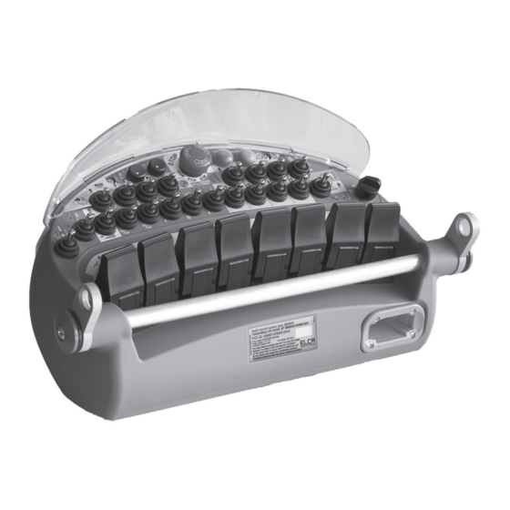
Remote control system for Drilling Machine
User manual
BRAVO
Industrial radio remote control
AT BRAVO-FUNK-915
Transmitting Unit
AR BRAVO-FUNK-915
Receiving Unit
ELCA S.r.l.
Via del Commercio, 7/b - 36065 Mussolente (VI) ITALY
www.elcaradio.com tel. +39 0424 578500 fax +39 0424 578520
ENG man BRAVO-FUNK-915 00
0408MA000x56
Advertisement
Table of Contents

Related Manuals for ELCA BRAVO


Summary of Contents for ELCA BRAVO
- Page 1 User manual BRAVO Industrial radio remote control AT BRAVO-FUNK-915 Transmitting Unit AR BRAVO-FUNK-915 Receiving Unit ELCA S.r.l. Via del Commercio, 7/b - 36065 Mussolente (VI) ITALY www.elcaradio.com tel. +39 0424 578500 fax +39 0424 578520 ENG man BRAVO-FUNK-915 00 0408MA000x56...
- Page 3 User manual...
-
Page 5: Table Of Contents
7.2 TRANSMITTING UNIT FUNCTIONAL CONTROL .................. 19 7.3 RECEIVING UNIT FUNCTIONAL CONTROL ..................20 7.4 CHARGING CYCLE FUNCTIONAL CONTROL ..................21 8. BRAVO-FUNK-915 RADIO REMOTE CONTROL TRANSMITTING UNIT ........8.1 GENERAL INFORMATION ..........................22 8.2 SPECIAL FUNCTIONS IN DRILLING MODE (WORK) ................23 8.3 SPECIAL FUNCTIONS IN DRILLING MODE (WORK) WITH CHARGER... -
Page 6: Federal Communications Commission (Fcc) Conformity And Frequencies
FREQUENCIES The radio link between the units of ELCA BRAVO-FUNK-915 series radio remote controls is built at one of the frequencies permitted by the US standards in force when the system is put on the market. -
Page 7: User Manual
This manual and any annexed documents are the property of ELCA and all rights are reserved. No parts of this publication may be reproduced or transmitted in any form or by any means, without written permission from ELCA. -
Page 8: Use Instructions
General block diagram The BRAVO type ELCA Radio Remote Control System is a family of industrial safety radio remote controls that can be used for the control of lifting, transportation and general equipment on machines where specific safety features are required on the Stop command (Cat. -
Page 9: Instructions For A Proper And Safe Use Of The Radio Remote Control System
ENG man BRAVO-FUNK-915 00 BRAVO-FUNK-915 Radio remote control system 2.3 INSTRUCTIONS FOR A PROPER AND SAFE USE OF THE RADIO REMOTE CONTROL SYSTEM. 4 Mounting points ANTENNA with vibration dampers with vibration dampers STOP mushroom button Battery Check Option Check... - Page 10 ENG man BRAVO-FUNK-915 00 BRAVO-FUNK-915 Radio remote control system IMPORTANT ! The installer of the radio remote control must: Carry out a thorough risk assessment on the use of the machine with the radio remote control. Assess that there are no hazardous conditions in the event the radio remote control stops due to the loss of the radio link.
-
Page 11: Information For Installation
ENG man BRAVO-FUNK-915 00 BRAVO-FUNK-915 Radio remote control system Indicator lights - SYSTEM ON IN WAIT FOR START: The green Battery Check LED flashes rapidly. - INDICATION OF SYSTEM ON. When the system is working properly and the battery is fully charged, the green Battery Check LED flashes slowly. - Page 12 ENG man BRAVO-FUNK-915 00 BRAVO-FUNK-915 Radio remote control system - Use decoupling systems for the receiver outputs when an electrical command other than the radio remote control is foreseen, except when use of the alternative command is made with the receiving unit of the radio remote control electrically disconnected from the machine.
-
Page 13: Maintenance
ENG man BRAVO-FUNK-915 00 BRAVO-FUNK-915 Radio remote control system 2.6 MAINTENANCE Before proceeding with any kind of maintenance make sure the receiver is not powered, that the transmitter is switched off and the emergency STOP button pressed. In the event it is necessary to intervene on the machine or on the receiving unit for maintenance operations, electrically disconnect the receiver unit from the machine. -
Page 14: Warranty
Warranty does not cover transport damage or loss. Elca shall not be held liable for damage to property or persons. Elca shall not be liable for machine down time and it is the user's responsibility to provide the option of manual or cable control for each machine. -
Page 15: Technical Data
3. TECHNICAL DATA 3.1 GENERAL FEATURES GENERAL FEATURES. Manufacturer ..............................ELCA S.r.l. Radio Remote Control System type ........................BRAVO Working frequency ..........................915.050 - 927.950 MHz Channel spacing used ............................. 50 kHz Working temperature ............................-25 - +55 °C Storage and transportation temperature......................-25 - +55 °C Operating range................................. -
Page 16: Charging System Features
ENG man BRAVO-FUNK-915 00 BRAVO-FUNK-915 Radio remote control system 3.4 CHARGING SYSTEM FEATURES Battery charger for battery pack LI-TE (7.4V - 17Wh [2.3Ah]) with Li-ion chemistry Battery charger model ..................... LITE-ION Power supply voltage .................... 12-30 V ] Absorbed current ......................< 1 A Rated output voltage .................... -
Page 17: Transmitting Unit
TX EXTENSION CARD. Permits to increase the available commands. The transmitting unit AT BRAVO-FUNK-915 univocally communicates with the receiver with its own receiver, because the transmitted signal contains an identification code inside it that is not reproducible. Recognition of this code allows the receiving unit to identify with certainty the unit that has transmitted the command. -
Page 18: Receiving Unit
5. RECEIVING UNIT 5.1 DESCRIPTION OF OPERATIONS The receiving unit AR BRAVO-FUNK-915 comprises several main electronic circuits: MOTHER BOARD. This contains the electronics for the decoding and implementation of the controls, the safety fuses, and backs up the radio module, the encryption key, the data memory and the expansion cards. - Page 19 ENG man BRAVO-FUNK-915 00 BRAVO-FUNK-915 Radio remote control system INTERNAL FUSES ANTENNA LED CARD RADIO CARD RECEIVER COMMANDS EXPANSION CARD PROPORTIONAL COMMANDS EXPANSION CARD ON/OFF MOTHER BOARD CONNECTOR OPENING - Page 13 -...
-
Page 20: Modifying The Proportional Function Parameters (Setup)
To exit the adjustment mode of the Offset voltage, it is necessary to exit the SETUP mode, switching the receiver off or moving the Elca Logo of the cable protection hood for approximately 10 seconds near to the area on the receiver indicated with Enable SETUP. - Page 21 To exit the adjustment mode of the Offset voltage, it is necessary to exit the SETUP mode, switching the receiver off or moving the Elca Logo of the cable protection hood for approximately 10 seconds near to the area on the receiver indicated with Enable SETUP.
-
Page 22: Battery Charger
ENG man BRAVO-FUNK-915 00 BRAVO-FUNK-915 Radio remote control system 6. BATTERY CHARGER 6.1 BATTERY CHARGER USAGE The battery must be recharged in an environment in which the temperature ranges between 0°C and 40°C. If the ambient temperature is outside the allowable temperature range, the charging process is interrupted and the red CHARGE LED flashes to indicate a fault. -
Page 23: Troubleshooting
ENG man BRAVO-FUNK-915 00 BRAVO-FUNK-915 Radio remote control system 7. TROUBLESHOOTING 7.1 TYPE OF TROUBLE - RADIO CONNECTION FAILURE: After having turned the key on the transmitter to position 1, the radio link does not activate when pressing Start. The radio connection is active and working when the green Battery Check LED flashes slowly (1 flash every second). - Page 24 ENG man BRAVO-FUNK-915 00 BRAVO-FUNK-915 Radio remote control system - MALFUNCTION OF THE RECEIVER UNIT: When the radio link is active and operational and the system works regularly on the receiving unit, the green POWER LED flashes slowly and the blue STATUS LED flashes rapidly. All other LEDs are off.
-
Page 25: Transmitting Unit Functional Control
ENG man BRAVO-FUNK-915 00 BRAVO-FUNK-915 Radio remote control system 7.2 TRANSMITTING UNIT FUNCTIONAL CONTROL Follow the diagram below (starting from the top left corner) to solve or identify the problem. WITH THE WITH THE KEY SELECTOR KEY SELECTOR REPLACE THE... -
Page 26: Receiving Unit Functional Control
ENG man BRAVO-FUNK-915 00 BRAVO-FUNK-915 Radio remote control system 7.3 RECEIVING UNIT FUNCTIONAL CONTROL Follow the diagram below (starting from the top left corner) to solve or identify the problem. CHECK THAT THE IS THE GREEN CHECK FUSE F2... -
Page 27: Charging Cycle Functional Control
ENG man BRAVO-FUNK-915 00 BRAVO-FUNK-915 Radio remote control system 7.4 CHARGING CYCLE FUNCTIONAL CONTROL Follow the diagram below (starting from the top left corner) to solve or identify the problem. CHECK THE FUSE AND CHECK CONNECTION REPLACE IT WITH... -
Page 28: Bravo-Funk-915 Radio Remote Control Transmitting Unit
JOY1 8.1 GENERAL INFORMATION The BRAVO-FUNK-915 radio remote control system has been developed to ensure the best operating performance and has some special features outlined below. The symbols illustrated in this document are indicative and may vary from one model to another. Refer to the specific documentation attached to the radio remote control. -
Page 29: Special Functions In Drilling Mode (Work)
ENG man BRAVO-FUNK-915 00 BRAVO-FUNK-915 Radio remote control system SELECTION OF THE OPERATING MODE The selector S13 selects the operating mode of the machine: Upon activation of the radio link with the receiver, this switch should be centrally positioned in the PLACING mode. - Page 30 ENG man BRAVO-FUNK-915 00 BRAVO-FUNK-915 Radio remote control system PULL, PUSH AND RAPID FUNCTION The Push function is activated with selector S2 in the upward position. The adjustment of the thrust force is made using potentiometer POT1. The Pull function is activated with selector S2 in the downward position and the pulling force is always the greatest in any position the potentiometer POT1 may be.
-
Page 31: Special Functions In Drilling Mode (Work) With Charger
ENG man BRAVO-FUNK-915 00 BRAVO-FUNK-915 Radio remote control system 8.3 SPECIAL FUNCTIONS IN DRILLING MODE (WORK) WITH CHARGER DRILLING MODE (WORK) WITH CHARGER - Activation of Charger mode: The selector S20 pushed upwards activates the Charger mode. To activate this mode, the Drilling mode must be on (Work) and selector S2 in the central position. -
Page 32: Correspondence Of Funk Unit Functions For Drilling Machine
ENG man BRAVO-FUNK-915 00 BRAVO-FUNK-915 Radio remote control system CORRESPONDENCE OF FUNK UNIT FUNCTIONS FOR DRILLING MACHINE SYMBOL FUNCTION (ANALOGUE) INDICATION ON THE JUNCTION BOARD Anl. Left Track 1. Anl. Cingolo SX Anl. Slewing ring / Oscillation Track 2. Anl. Ralla / Brandeggio 3.
Need help?
Do you have a question about the BRAVO and is the answer not in the manual?
Questions and answers