Table of Contents
Advertisement
Quick Links
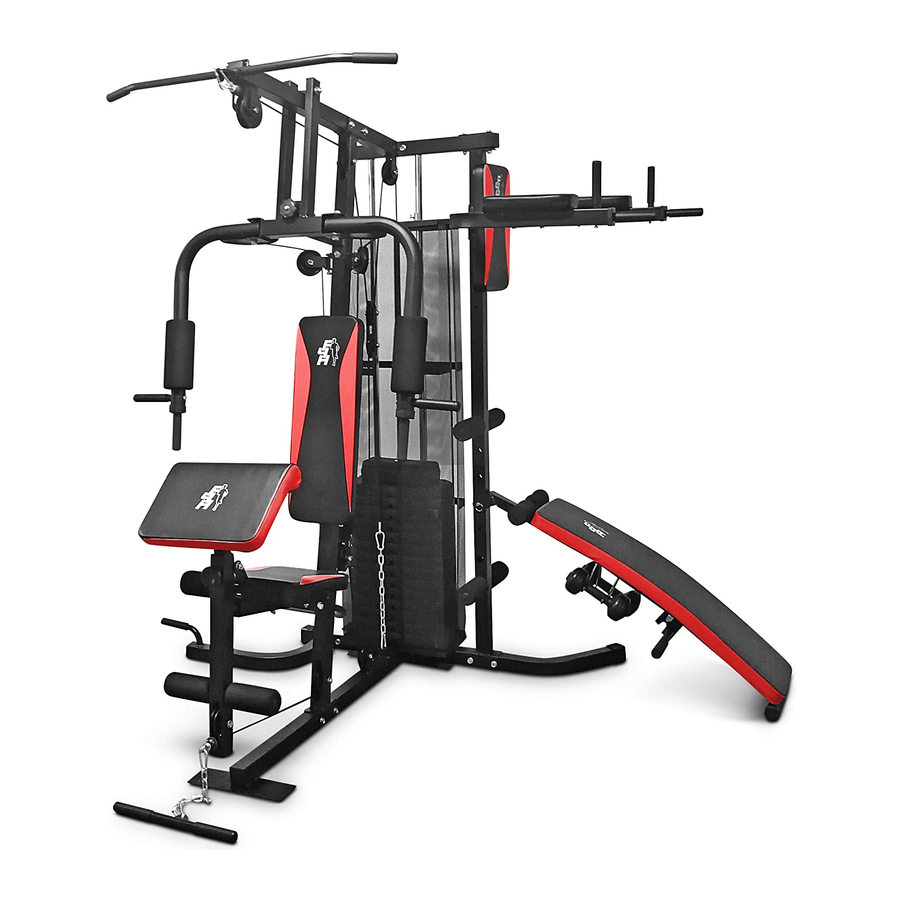
USER MANUAL
MAXX1 TF-7005A
Please Keep For Future Reference
5T-B0C3-VZLB
IMPORTANT - Please Read Instructions Fully Before Assembly Or Use
These instructions contain important information which will help you get the best
from your equipment and ensure safe and correct assembly, use and maintenance.
If you need help or have damaged or missing parts,
call the Customer Helpline: 0330 124 0718 (Opening hours: Mon-Fri 9:00am-3:00pm)
or Email: customerservices@fit4home.co.uk
1
Advertisement
Table of Contents

Subscribe to Our Youtube Channel
Related Manuals for Fit4Home MAXX1 TF-7005A


Summary of Contents for Fit4Home MAXX1 TF-7005A
- Page 1 USER MANUAL MAXX1 TF-7005A Please Keep For Future Reference 5T-B0C3-VZLB IMPORTANT - Please Read Instructions Fully Before Assembly Or Use These instructions contain important information which will help you get the best from your equipment and ensure safe and correct assembly, use and maintenance.
-
Page 2: Table Of Contents
CONTENTS Safety Information 03-04 Parts Chart 05-06 Parts List Assembly Instructions 08-24 Step 1 Step 2 Step 3 Step 4 Step 5 Step 6 Step 7 Step 8 15-16 Step 9 19-20 Step 10 Step 11 22-23 Step 12 Declaration... -
Page 3: Safety Information
IMPORTANT SAFETY INFORMATION SAFETY INFORMATION Be sure to read the entire instruction manual before you assemble or use this equipment. Particularly, note the following safety precautions. • Exercising. Do not wear loose clothing that could get caught in the equipment. Appropriate footwear is also required when using the equipment. - Page 4 IMPORTANT SAFETY INFORMATION INSTRUCTIONS WHEN ASSEMBLING • Check you have all the components and tools listed in the instruction manual. • Remove all fittings from the plastic bags and separate them into different groups. • Keep children and animals away from the work area, (small components can causechoking if swallowed).
- Page 5 PARTS LIST...
- Page 6 PARTS LIST...
-
Page 7: Parts List
PARTS LIST... -
Page 8: Assembly Instructions
ASSEMBLY INSTRUCTIONS STEP 1 1. The straight bottom tube (A1) is connected to the transverse bottom tube (A2). Use bolt (B3) washer (B17) and nut (B13). 2. The left bottom bend pipe (A3) is connected with the right bottom tube (A4) to the transverse bottom tube (A2). - Page 9 ASSEMBLY INSTRUCTIONS STEP 2 The two guide rods (A6) are inserted into the transverse bottom tube (A2) through the protective net cover frame. Use two rubber washer (E4) washer (B17) bolts (B5) and nuts (B13). The counterweight block (E23) penetrates into the guide rod (A6).
-
Page 10: Step 3
ASSEMBLY INSTRUCTIONS STEP 3 1. Connecting the middle column (A7) to the straight bottom pipe (A1).Usewasher (B17) bolts (B3) and nuts (B13). 2. Connect the side bracket (A8) to the long transverse bottom tube (A2). Use washer (B17) bolts (B3) and nuts (B13). -
Page 11: Step 4
ASSEMBLY INSTRUCTIONS STEP 4 1. The upper connecting pipe (A9) is installed on the 2 guide rods (A6).Use washer (B18) bolt (B9).Connected to Ce Lizhu (A8), Use washer (B17)bolts (B3) and nuts (B13). 2. Install upper bracket (AlO) on the middle column (A7),Use washer (Bl7)bolts (B3) and nuts (B13).Then the upper bracket (A10) is connected to the upper connecting pipe (A9), Use washer (B17) bolts (B3) and nuts (B13). -
Page 12: Step 5
ASSEMBLY INSTRUCTIONS STEP 5 The seat tube (A11) installed in the column (A7).Use washer (B17) bolts (B3) and nuts (B13) The seat cushion connecting frame (B25) installed in the seat tube (A11). Use washer (B17) and nut (B13). Install the support tube (a27) between the seat cushion tube (a11) and the straight bottom tube (A1) and secure with washer (B17), carriage bolt (B28) and nut (B13) The seat cushion (E25) installed in the connecting frame (B25) on.Use washer(B18) and bolt (B10). -
Page 13: Step 6
ASSEMBLY INSTRUCTIONS STEP 6 1. The small support (A14) installed in the middle column (A7). Use washer (B17) bolts (B4) and nuts (B13). 2. The single pulley block (D3) installed in the middle column (A7).Use washer (B17) bolts (B5) and nuts (B13). 3. -
Page 14: Step 7
ASSEMBLY INSTRUCTIONS STEP 7 1. Insert the Bearing(C2) to the chest press (A15) and the Upper barcket(A10),fixed them by bolt(B1), washer(B16),nut(B12). 2. Install the adjusting screw (B24) on the middle column cross member(A7).Use screw (B8) nut(B14) and washer (B23) knob (B20). 3. - Page 15 ASSEMBLY INSTRUCTIONS STEP 8 1. The support arm (A19 and A20) connected to Ce Lizhu (A8).Use washer (B17) bolts (B3) and nuts (B13). 2. The small back pad (A24) needs to be installed on vertical frame 2 (A8). To secure use 2 washers (B17) and 2 screw bolts (F1).
- Page 16 ASSEMBLY INSTRUCTIONS...
- Page 17 ASSEMBLY INSTRUCTIONS...
- Page 18 ASSEMBLY INSTRUCTIONS...
- Page 19 ASSEMBLY INSTRUCTIONS STEP 9 1. The upper wire rope (E29) through the 1-1 pulley, Install pulley and pulley cover (E2) (E29.)Use bolt (B6) nut (B13). 2. And then through the 1-2 pulley frame,Use of the pulley (E3) and the sleeve (E16),Washer (B17) bolts (B3) and nuts (B13).
- Page 20 ASSEMBLY INSTRUCTIONS STEP 9 4. And then through the 1-4 pulley frame. Use pulley (E3) bolts (B7) and nuts (B13). 5. And then installed on the 1-5 combination.Use washer (B23) weight block top block (E22) weight block (E23) selector lever (A5).
- Page 21 ASSEMBLY INSTRUCTIONS STEP 10 1. The butterfly arm wire rope (E31) is installed on the 2-1 combination. Using bolt (B9) nut (B14). 2. And then through the 2-2 pulley rack,Use single pulley block (D3) pulley (E3) bolt (B7) nut (B13). 3.
- Page 22 ASSEMBLY INSTRUCTIONS STEP 11 1. The lower wire rope (E30) through the 3-1 pulley,Use of the pulley sleeve (E3) (E16) (B3) bolt nut (B13). 2. And then through the 3-2 pulley, Use of the pulley sleeve (E3) (E16) (B3) and bolt nut (B13). 3.
- Page 23 ASSEMBLY INSTRUCTIONS STEP 11 4. And then through the 3-4 single pulley frame,Using pulley (E3) bolt (B7) nut (B13). 5.And then through the 3-5 pulley block,Using pulley (E3) bolt (B7) nut (B13). 5. And then through the 3-5 pulley block,Using pulley (E3) bolt (B7) nut (B13).
- Page 24 ASSEMBLY INSTRUCTIONS STEP 12 1. Install the high tension bar (A23) on 2. The lower tie rod (A24) is installed the 4-1 combination, using the wire on the 4-2 assembly, and the wire harness clip (C4). harness clamp (C4) chain(C5) is used. 3.
-
Page 25: Declaration
Declaration of Conformity We, Importer Fit4home Ltd Unit A, Perseverance Mills, Olive Lane, Darwen BB3 3DQ United Kingdom Declare that the product TF-7005A Home Gym Complies with the essential health and safety requirements of the following directive: Direction for 2014/357/EU for Stationery training equipment...
Need help?
Do you have a question about the MAXX1 TF-7005A and is the answer not in the manual?
Questions and answers