
Related Manuals for Fromm P356.0001.01


Summary of Contents for Fromm P356.0001.01
- Page 1 SERVICE MANUAL PNEUMATIC PLASTIC STRAPPING TOOL MODEL P356.0001.01 Manual for authorized dealers and service points...
- Page 2 CONVERSION PARTS 1.2 CONVERSION PARTS When converting strap thickness or strap width the following parts must be exchanged: 16 x 16 x 19 x 19 x 19 x 0.65-1.05 1.06 -1.35 0.40-0.64 0.65-1.05 1.06-1.35 Holder P32.1228 P35.3210 P32.1228 P32.1228 P35.3210 Holder P32.1229 P35.3209 P32.1229 P32.1229 P35.3209 Strap guide...
- Page 3 PERIODIC MAINTENANCE AND CONTROL 1.3.4 Glueing rules Following parts have to be glued with LOCTITE 603: N2.2145 Planet shaft P35.3103 with the parallel pins N2.2145. P35.3103 Tensioning body P35.3204/05 with the parallel pins N2.2189 Body P35.3101 with swivel shaft P35.3102 and parallel pins N21.2101 P35.3204/05 N2.2189...
- Page 4 PERIODIC MAINTENANCE AND CONTROL 1.3.5 Lubrication rules P32.1029 All bearing parts of the welding unit have to be cleaned and N3.1702 (6X) lubricated with Klueber Isoflex Alltime SL2 grease during each maintenance. Bearing welding unit Lubrication interval: P32.1027 At each maintenance or after 12 months at the latest. P32.1511 All movable gear parts have to be lubricated with MOLYKOTE BR 2 PLUS grease.
- Page 5 PERIODIC MAINTENANCE AND CONTROL Assembling position of the shaft P35.3111 When installing the motor cell P35.0131 pay attention to the correct position of the shaft P35.3111. (see drawing) P35.0131 P35.3111 Needle free wheeling: Pay attention to the assembling direction of the needle free wheeling N3.4509.
- Page 6 PERIODIC MAINTENANCE AND CONTROL Grippers: When installing the grippers into the tensioning body P35.3204/05 pay attention to the direction of the teeth.(see drawing) P35.3204/05 Grippers Elastomer Spring and Thrust Piece: P35.3110 When assembling the motor cover P35.3110, pay attention to the assembling direction of the spring P35.2026 and the thrust piece P35.2027.
- Page 7 RECOMMENDED SPARE PARTS Gear body: When assembling or disassembling the P35.3116 gear body (P35.3117) the sustaining ring (P35.3116) of the turn off valve must be pressed down. The spring N2.5822 must be slightly lifted up. (see drawing) N2.5822 P35.3117 1.4 RECOMMENDED SPARE PARTS Following spare parts are recommended for stock keeping: Item-No.
-
Page 8: Table Of Contents
ACCESSORY TOOLS 1.5 ACCESSORY TOOLS Item Field number N71.3235 *a,d Press in and press out arbor for N3.4509/P35.3118 N71.3238 *a,d Press in and press out pressure pad for N3.1159/P32.1037 N71.3239 *a,d Press in arbor for N3.2347/P32.1510 N71.3240 *a,d Press out arbor for N3.2347/P32.1510 N71.3241 *a,d Press in and press out pressure pad for N3.2347/P32.1510... - Page 9 ACCESSORY TOOLS 1.5.1 Use of accessory tools N7.5108 Accessory tools should only be used with the suitable arbor press N7.5108 in order to avoid a tilt of the pressed in parts. Additional a retainer (N7.3215) is necessary. N7.3215 Part Disassembly Assembly N3.1157/ P35.3103...
-
Page 10: N71.3238 *A,D F3
ACCESSORY TOOLS Part Disassembly Assembly N3.1159/ P32.1037 N71.3237 N3.1159 P32.1037 N71.3238 N3.3150/ N71.3248 P35.3204 N71.3267 P35.3205 N3.3150 N71.3268 P35.3204/05 N3.4509/ N71.3235 P35.3118 N3.4509* P35.3118 N71.3278 *Assembling position see „Assembly information“ 1-19... -
Page 11: N71.3239 *A,D F7
ACCESSORY TOOLS Part Disassembly Assembly P32.1023/ N3.1134/ N71.3243 N71.3244 P35.3123 P35.3123 N3.1134 N71.3245 P32.1023 N3.2347/ N71.3239 P32.1510 N71.3240 N3.2347 P32.1510 N71.3241 The seal of the needle bushing (N3.2347) has to face to the outside. N3.2356/ P35.3211 N71.3237 N71.3266 N3.2356 P35.3211 N71.3245 1-20... -
Page 12: N71.3254 *A,D F9
ACCESSORY TOOLS Part Disassembly Assembly P32.1023/ P35.0140 Picture 1 N71.3244 N71.3254 P32.1023 N71.3280 P35.0140 N71.3255 Picture 2 N71.3281 1-21... -
Page 13: N71.3276 *D F10
ACCESSORY TOOLS Part Disassembly Assembly P35.2023/ N3.1174/ P35.3138 bzw. Commercially P35.3106 The distance between rotor (P35.3138 available Puller. resp. P35.3106) and end plate (P35.2023) should be 0,03 mm N71.3277 P35.3138 P35.3106 P35.2023 N3.1174 N71.3276 1-22... - Page 14 ACCESSORY TOOLS Proceeding for valve disassembling: • Press clip together and insert it into the hole, until it engages in the exhaust ring • Insert coupler pull out exhaust ring Attention! When disassembling the valves don’t damage the ball seat. Part Disassembly P35.2005/...
- Page 15 ACCESSORY TOOLS Part Disassembly P35.2059/ P35.3141 N71.3274 P35.2059 Hook in here P35.3141 P35.3142/ Disassembly with N71.3274 P35.3141 P35.3142 P35.3141 Hook in here 1-24...
-
Page 16: N71.3214 *C F14
ORDERING SPARE PARTS Part Disassembly P35.2057/ P35.3141 P35.2057 N71.3214 P35.3141 Hook in here 1.6 ORDERING SPARE PARTS On principle spare part numbers should be taken from the drawings or spare parts lists. Check if the version number of the tool and the spare parts list are the same. Type dependent spare parts should be ordered as follows: Ordering example Ordering a tensioning wheel:... - Page 17 P35.0131 N3.1174 P35.0129 P35.3109 N2.2403 P35.3101 P35.3107 N2.2402 5x P35.2022 5x P35.3108 N21.2101 P35.3106 5x P35.2022 N3.1172 P35.3201 P35.2023 N3.2107 N3.1174 N6.6237 P32.1712 P35.2027 P35.2026 P35.3202/03 P35.3110 P32.1229/P35.3209 N3.1172 P32.1228/P35.3210 N3.2356 P35.3211 P35.3102 N4.9159 N1.1818 P32.1718/21/P35.3208 N2.4902 P32.1719/16 P32.1246/1724 N1.6503 P35.3206 P35.3212/13 N1.1904...
- Page 18 P35.3116 P35.3113 N6.6121 P35.0134 N6.6211 N3.1160 P35.2029 P35.0132 P35.2031 P35.3112 N2.5291 N6.6163 N3.1178 N6.6235 P35.3115 N2.1610 P35.2032 N6.6235 N1.2112 P35.0133 P35.3114 N6.6268 P35.3105 N6.6121 P35.3104 N1.1935 N6.6211 N2.2145 P35.3114 P35.3103 N6.6121 N1.3128 N3.2105 N3.1157 N6.6211 P35.2038 N21.2108 P35.0130 P35.1344 P35.3101 P35.3111 N2.5259 N1.1936...
- Page 19 N1.1820 N41.9129 N2.4902 N42.9147 P35.3136 N1.1818 P35.0137 P35.3134 N1.6331 P35.3135 P35.3126 P35.3131 P35.3133 N61.6206 N3.1159 N2.2485 N2.5152 N1.5602 P35.3121 N6.6280 P32.1037 N6.3407 N1.6331 P35.3130 P35.3132 P35.0138 N2.2190 P35.2009 P35.0149 P32.1012 P35.0137 N6.6117 N2.5276 P35.3129 P35.0136 P35.2005 P35.2008 P32.1023 N6.6280 N1.1553 P32.1251 N3.1134 N3.1711...
- Page 20 P35.3137 N2.1606 P35.2064 N1.1813 P35.0140 P35.2026 P35.0142 P35.2027 N3.1174 P35.2023 N2.1118 N2.2402 P35.3107 P35.3158 P32.1212 N6.6291 P35.3156 N6.6291 5x P35.2022 P35.3138 P35.3155 P35.3109 N6.6185 N2.2403 5x P35.3108 N2.5292 N3.1174 N6.6117 5x P35.2022 P32.1023 P35.3144 N6.6117 P35.3157 N6.6298 N2.2114 P35.3149 P35.3140 N2.2101 N6.6117 P35.3101...
- Page 21 P35.3159 P35.3137 N2.5280 P35.3145 N6.6117 P35.3146 P35.3144 P35.2061 N6.6117 N2.1301 N6.6291 P35.3143 N6.6117 N6.6283 N6.6291 P35.3142 P35.2059 N3.1702 P35.3158 P35.2060 N6.6269 N2.5224 N11.1191 P35.3141 N6.6157 N1.6506 P35.2058 P35.2057 N1.1106 N6.5137 N6.6269 (N6.6501) N6.6269 N5.2702 P35.3147 P35.2062 P35.3148 Mobil Velocite No. 6 Mobilux EP2 Molykote BR2 plus Klüber Isoflex Alltime SL2...
- Page 22 SPARE PARTS LIST P356 3.1 Type independent spare parts P356.0001.01 Item-No. in group Pcs. Description Dimension Field N11.1191 P35.0139 2 FLAT HEAD SCREW M6 X 100 N1.1106 P35.0142 2 SCREW M6 X 20 N1.1305 P35.0128 2 SCREW M4 X 7.8 N1.1553...
- Page 23 Item-No. in group Pcs. Description Dimension Field N2.2403 P35.0131 1 DOWEL PIN 3 X 16 N2.2403 P35.0140 1 DOWEL PIN 3 X 16 N2.2485 P35.0129 1 DOWEL PIN 4 X 8 N2.3342 P35.0128 1 FEATHER KEY 2 X 2 X 10 N2.4902 4 HAMMER HEAD BOLT 1.85 X 4.76...
- Page 24 Item-No. in group Pcs. Description Dimension Field N6.6121 P35.0141 3 SEAL 8 X 15 X 2.3 N6.6147 P35.0142 1 SEAL 10 X 17 X 2.3 N6.6157 P35.0142 2 PACKING RING 4 MM N6.6163 P35.0134 1 SEAL 10 X 13.6 X 2.3 N6.6185 P35.0142 1 PACKING RING...
- Page 25 Item-No. in group Pcs. Description Dimension Field [P35.0142] P35.0139 1 VALVE HEAD A24+ [P35.0145] 1 END COVER [P35.0146] 1 COUPLER [P35.0147] 1 SUSPENSION [P35.0149] P35.0128 1 WELDING EXCENTRIC P35.1344 P35.0128 1 SLIDE GATE P35.2005 P35.0128 1 EXHAUST RING P35.2008 P35.0128 1 BEARING SUPPORT P35.2009 P35.0128...
- Page 26 Item-No. in group Pcs. Description Dimension Field P35.3115 P35.0128 1 COUPLER P35.3116 P35.0128 1 SUSTAINING RING P35.3117 P35.0128 1 GEAR BODY P35.3118 P35.0135 1 SPUR WHEEL P35.3119 P35.0128 1 EXHAUST SILENCER [P35.3120] P35.0128 1 GEARING COVER P35.3121 P35.0128 1 SEAL PLATE P35.3123 P35.0149 1 WELDING EXCENTRIC...
- Page 27 3.2 Type dependent spare parts P356.0001.01 Type 49.0363.01 49.0363.01 P356/16/0.65-1.05 P356.0001.01 09.08.04 Item-No. in group Pcs. Description Dimension Field P32.1228 1 HOLDER P32.1229 1 HOLDER P32.1246 1 STRAP GUIDE P32.1719 1 GRIPPER P32.1720 1 GRIPPER P32.1721 1 GRIPPER P32.1722 1 STRAP STOP [P35.0143]...
- Page 28 Type 49.0374.01 49.0374.01 P356/19/0.65-1.05 P356.0001.01 09.08.04 Item-No. in group Pcs. Description Dimension Field P32.1228 1 HOLDER P32.1229 1 HOLDER P32.1719 1 GRIPPER P32.1720 1 GRIPPER P32.1721 1 GRIPPER P32.1723 1 STRAP STOP P32.1724 1 STRAP GUIDE [P35.0143] 1 TENSIONING BODY 1 TENSIONING WHEEL P35.3203...
- Page 29 OPERATION MANUAL PNEUMATIC PLASTIC STRAPPING TOOL MODEL P356.0001.01 CE Declaration of conformity We declare that the machine P356 is in conformity with the following standard or standardised documents: 98/37/EEC FROMM Holding AG Hinterbergstrasse 26 CH - 6330 Cham 14.05.2004 R.Fromm...
- Page 30 4.6 INSTALLATION 4.6.1 Compressed air connection The compressed air is to be connected to the tool preferably by a quick disconnecter (G1/4). An air-unit consisting of a separator for water and dirt, a pressure regulator with a manometer and a lubricator must be installed within a range of 15 ft / 5 meters.
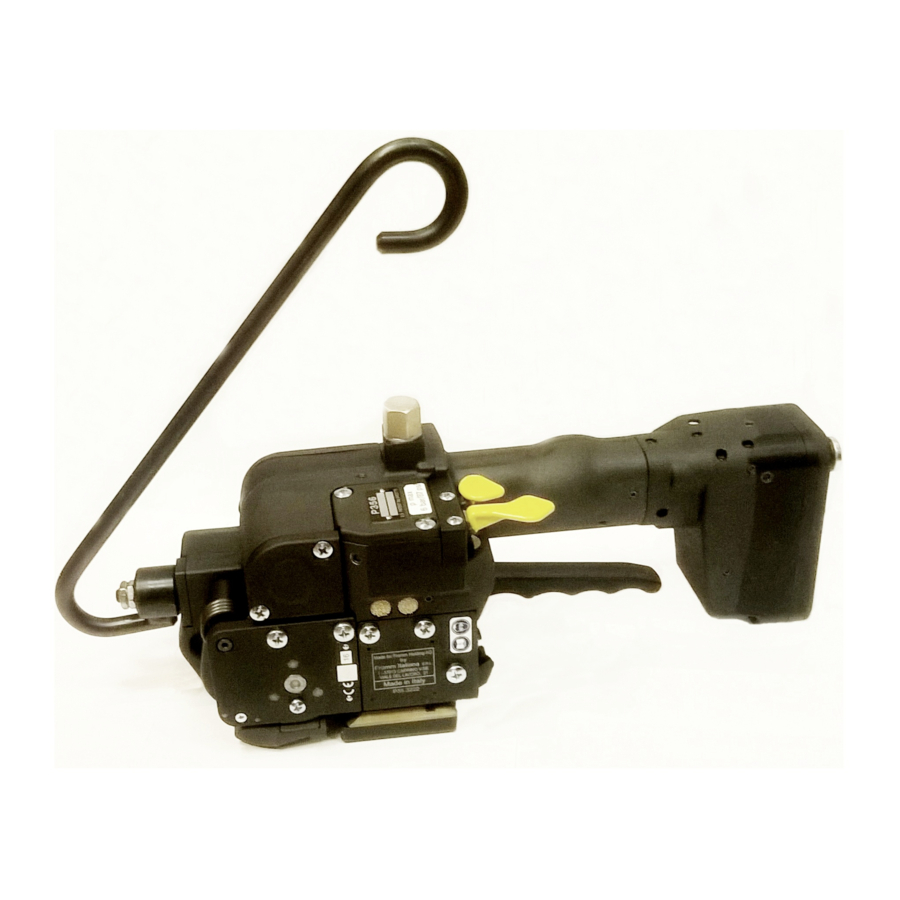
- Page 31 Suspension of tool It is possible to suspend the tool on a spring loaded balancer using the suspension bracket P35.0147 which is supplied with the tool. The suspension bracket has been designed in such a way, that the tool can be used for all three working positions.
- Page 32 4.9 EXCHANGE OF WEARING PARTS Before any maintenance work always disconnect the tool from the air supply. 4.9.1 Exchange of tensioning wheel and grippers Disassembling • Unscrew end cover P35.3211 and remove it; • Remove the torsion spring N2.5823; • Remove the tensioning body;...
- Page 33 4.9.2 Exchange of cutter, welding stop gripper and welding gripper Disassembling • Disassemble security ring N2.1118, pull the grip axle P35.2064 from the tool. • Tilt down the handle lever P32.1212 and remove it from the tool. • Remove cover P35.3222 and end cover P35.3211. •...
- Page 34 Assembling Assembling in opposite order. Observe the following: When inserting the piston pay attention to the proper seat of the piston in the thrust piece. Pay attention to the fitting position of the cutter (see drawing). Safe the screws N1.1305 with Loctite 222 Lubrication •...
Need help?
Do you have a question about the P356.0001.01 and is the answer not in the manual?
Questions and answers