Table of Contents
Advertisement
Quick Links
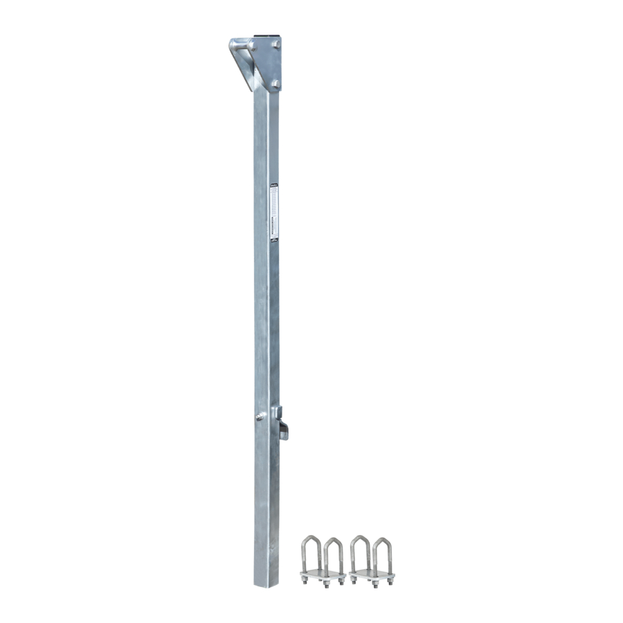
Ladder Stanchion Anchors
User Instruction Manual
6160505
6160512
6161012
6161005
6160512W
This manual should be used as part of an employee training program as required by the Occupational Safety and
Health Administration (OSHA).
MANC29 REV B
1306 S. Alameda Street, Compton, CA 90221, USA Tel: 800-719-4619 Fax: 323-752-5613
022020
Advertisement
Table of Contents

Related Manuals for Falltech 6160505


Summary of Contents for Falltech 6160505
- Page 1 Ladder Stanchion Anchors User Instruction Manual 6160505 6160512 6161012 6161005 6160512W This manual should be used as part of an employee training program as required by the Occupational Safety and Health Administration (OSHA). MANC29 REV B 1306 S. Alameda Street, Compton, CA 90221, USA Tel: 800-719-4619 Fax: 323-752-5613...
-
Page 2: Table Of Contents
Definitions ........................... Appendix A ......................... For purposes of this manual, the FallTech Ladder Stanchion Anchor in all iterations may be referred to as the Ladder Stanchion Anchor, Ladder Stanchion, the anchor, the anchorage connector, the equipment, the product, or the unit. -
Page 3: Warnings And Important Information
Do not alter or intentionally misuse this equipment. • Consult FallTech when using this equipment in combination with components or subsystems other than those described in this manual. • Do not connect rebar hooks, large carabiners, or large snap hooks to the FBH dorsal D-rings as this may cause a roll-out condition and/or unintentional disengagement. -
Page 4: Definition
3.4.1 Personal Fall Arrest: The FallTech® Ladder Stanchion Anchor used as the anchorage component of a PFAS to protect the user in the event of a fall. -
Page 5: Assembly, Installation, And Use
WARNING Do not alter or intentionally misuse this equipment. Consult FallTech® when using this equipment in combination with components or subsystems other than those described in this manual. Installation of the Cable Anchor must be done under the supervision of a Competent Person trained in its design and use. - Page 6 5.2 Bolt-On Ladder Stanchion Anchor Installation Before installation, ensure fixed ladder meets minimum strength requirements of 1,200 lbs Minimum Ultimate Strength per rung, rungs are 1/2” to 1-1/4” diameter, and have a spacing of 12” +/- 2”. Ensure structure and fixed ladder connections to the structure can withstand a load of 3,600 lbs in both the downward and outward directions.
- Page 7 When torqueing V-Bolts, it is necessary to alternate the tightening of the nuts in small increments to ensure the V-Bolt is evenly tightened. 5.2.7 Install compatible FallTech SRL to attachment point using approved loading carabiner. Connect tagline to SRL. Figure 8 - Bolt-On Stanchion Installation: Step 1...
- Page 8 5.3.2 Apply adequate corrosion protection to welded and exposed metal meeting local standards. 5.3.3 Install compatible FallTech SRL to attachment point using approved carabiner. Connect tagline to SRL. Figure 12 - Weld-On Stanchion Installation Figure 13 - Weld-On Stanchion Orientation...
-
Page 9: Maintenance And Service
Inspection 7.1 Pre-Use Inspection: FallTech® requires that the following steps be taken during each inspection prior to use of this product. 7.1.1 Inspect the Stanchion Anchor and hardware. These items must not be damaged, broken, distorted, or have any sharp edg- es, burrs, cracks, worn parts, or corrosion. - Page 10 Inspection Record Model #:_________________________ Serial #:_________________________ Date of Manufacture:_________________________ INSPECTION INSPECTOR COMMENTS PASS/FAIL CORRECTIVE ACTION NEEDED APPROVED BY DATE MANC29 REV B 022020...
-
Page 11: Labels
Do not side load or misuse this product. Do not use if unsafe conditions are present. Always log inspection results in the user manual. 800.719.4619 • www.falltech.com 800.719.4619 • www.falltech.com 412-04738 Rev A 412-04216 Rev A DO NOT... -
Page 12: Definitions
Definitions The following are general definitions of fall protection terms as defined by ANSI Z359.0-2012. Anchorage -A secure connecting point or a terminating component of a fall protection system or rescue system capable of safely supporting the impact forces applied by a fall protection system or anchorage subsystem. Anchorage Connector - A component or subsystem that functions as an interface between the anchorage and a fall protection, work positioning, rope access or rescue system for the purpose of coupling the system to the anchorage. - Page 13 Horizontal Lifeline – A component of a horizontal lifeline subsystem, consisting of a flexible line with connectors or other coupling means at both ends for securing it horizontally between two anchorages or anchorage connectors. Horizontal Lifeline Subsystem – An assembly, including the necessary connectors, comprised of a horizontal lifeline component and, optionally, of: a) An energy absorbing component or, b) A lifeline tensioner component, or both.
- Page 14 Height (A) Offset (B) 6161012 10’ 12” 6161005 10’ 5” REVISIONS N EMBODIED IN THIS DOCUMENT IS STRICTLY 6160505 5’ 5” ND ARE SUPPLIED WITH THE UNDERSTANDING DESCRIPTION DATE OT BE DISCLOSED TO THIRD PARTIES P1 PRELIMINARY INITIAL RELEASE 6160512 5’...
Need help?
Do you have a question about the 6160505 and is the answer not in the manual?
Questions and answers