Table of Contents
Advertisement
Quick Links
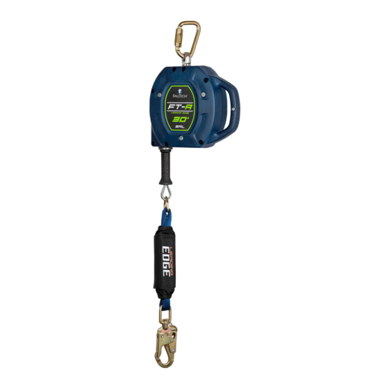
FT-R
SRL Leading Edge
TM
User Instruction Manual
412-05723 Rev B
This manual is intended to meet the Manufacturer's Instructions as required by the American National Standards
Institute (ANSI) Z359 and Canadian Standards Association (CSA) Z259 and should be used as part of an employee
training program as required by the Occupational Safety and Health Administration (OSHA).
MSRD20 Rev B
FallTech 1306 S. Alameda Street Compton, CA 90221, USA Tel: 800-719-4619 Fax: 323-752-5613
110421
Advertisement
Table of Contents

Related Manuals for Falltech FT-R SRL


Summary of Contents for Falltech FT-R SRL
- Page 1 Institute (ANSI) Z359 and Canadian Standards Association (CSA) Z259 and should be used as part of an employee training program as required by the Occupational Safety and Health Administration (OSHA). MSRD20 Rev B FallTech 1306 S. Alameda Street Compton, CA 90221, USA Tel: 800-719-4619 Fax: 323-752-5613 110421...
-
Page 2: Table Of Contents
Table of Contents Warnings and Important Information .................. Description .......................... Application ........................... System Requirements ......................Installation and Use ......................Maintenance, Service and Storage ..................Inspection ..........................Labels ........................... Definitions ........................... Appendix A ......................... For purposes of this manual, the FT-R SRL Leading Edge in all iterations may be referred to collectively as the FT-R, the SRL-LE , the SRD Leading Edge (SRD-LE), the self-retracting device (SRD), the equipment, the device, the product, or the unit. -
Page 3: Warnings And Important Information
Do not alter or intentionally misuse this equipment. • Consult FallTech when using this equipment in combination with components or subsystems other than those described in this manual. • Do not connect rebar hooks, large carabiners, or large snap hooks to the FBH dorsal D-rings as this may cause a roll-out condition and/or unintentional disengagement. -
Page 4: Description
Figure 10 for typical extreme sharp edges. This manual contains one Appendix that contains figures and tables specific to the FT-R SRL Leading Edge discussed in this manual. The SRD discussed in this manual may be attached to an overhead anchorage, i.e., from directly over the user’s head, to as low as the level of the user’s FBH dorsal D-ring. - Page 5 CSA Z259.2.2-2017. CSA requires that all SRDs be classified according to their respective type, and are classified either as; Class SRL, Class SRL-R, Class SRL-LE, or Class SRL-LE-R. The FT-R SRL-LE Self Retracting Device in this manual is Class SRL-LE.
-
Page 6: Application
Application Purpose: The FallTech FT-R SRL Leading Edge is designed to be used as a component in a Personal Fall Arrest System (PFAS), to provide a combination of worker mobility and fall protection as required for inspection work, general construction, maintenance work, oil production, confined space work, etc. - Page 7 Figure 3 - Non-Compatible Connections Never connect two active components (snap hooks or carabiners) to each other. Never connect two active components (snap hooks or carabiners) to a single D-ring at the same time. Never connect in a way that would produce a condition of loading on the gate. Never attach to a object in a manner whereby the gate (of the snap hook or carabiner) would be prevented from fully closing and locking.
-
Page 8: Installation And Use
WARNING Do not alter or intentionally misuse this equipment. Consult FallTech when using this equipment in combination with components or subsystems other than those described in this manual. All components or subsystems used with the SRD discussed in this manual must be in compliance with ANSI Z359, CSA Z259, and/or OSHA. - Page 9 Calculating Minimum Required Fall Clearance Figure 4 - MRFC Overhead Anchorage 5.2.1 30’ FT-R in Overhead, Non-Leading Edge Anchorage Application The 30’ FT-R may be used may be used as a standard SRD in an overhead condition, in which the SRD is installed anywhere in the allowable attachment X-SRD Anchorage Height Above Dorsal D-ring area, which ranges from directly above the user to level with the FBH D-ring, as...
- Page 10 Figure 4 - MRFC Non-Overhead Anchorage 5.2.2 30’ FT-R Non-Overhead Anchorage The leading edge/below D-ring condition minimum required fall clearance (MRFC) is calculated using five metrics, measured from the walking- working surface: SRD Deceleration Distance, D-Ring Shift and Harness Stretch [1 ft (0.3m)], Safety Factor [1.5 ft (0.5m)], Dorsal D-ring Height [5 ft (1.5m)], and Swing Fall.
- Page 11 WARNING An expanded work zone combined with an SRD attached at or near foot level will have a high risk of serious injury or death. Angle of Redirection: The angle of redirection is the angle of the lifeline over an edge during a fall event. Install the SRD so that the angle of the two parts of the lifeline are at least 90°, or more, but never less, as shown in Figure 10.
- Page 12 Incorrect Use: Additional factors to avoid, shown in Figure 12: Do not allow the lifeline to drape over and edge during normal work as this may abrade, damage, or otherwise compromise the lifeline. Do not attach the anchor on one side of an opening and work on the other side, as this creates multiple possible leading edges and potential swing fall hazards.
-
Page 13: Maintenance, Service And Storage
Service: If service is required for any reason; inspection failure, impact loaded, any type of malfunction, tag the unit as “UNUSABLE”, store separately, and contact FallTech at 800-719-4619 to receive a Return Authorization number or to locate the nearest FallTech Service Center. -
Page 14: Inspection
Inspection Pre-Use User Inspection: Perform an inspection before each use in accordance with the recommendations in Table 1 below. Table 1 - Guidelines for Cable SRD Inspection Inspection Pass Fail The cable lifeline should extract and retract completely and without faltering and should remain taut under tension without sagging. Extract the cable lifeline several inches and apply a firm pull to confirm the SRD locks. - Page 15 Inspection Checklist: Use Table 1: Guidelines for Cable SRD Inspection to inspect the SRD. See Figure 14 for examples of cable damage. Inspection Results: If an inspection reveals defects in or damage to the equipment, inadequate maintenance or activated fall indicators, remove the equipment from service.
-
Page 16: Labels
Labels Labels: The labels must be present and legible. Always read and follow the manufacturer’s instructions, labels and warnings before use. Failure to do so can result in serious injury or death. Adhere to the hierarchy of controls described in ANSI Z359.2. Before each use, test the device for locking and retraction, and inspect according to the manufacturer’s instructions. -
Page 17: Definitions
Definitions The following are general definitions of fall protection terms as defined by ANSI Z359.0-2012. Anchorage -A secure connecting point or a terminating component of a fall protection system or rescue system capable of safely supporting the impact forces applied by a fall protection system or anchorage subsystem. Anchorage Connector - A component or subsystem that functions as an interface between the anchorage and a fall protection, work positioning, rope access or rescue system for the purpose of coupling the system to the anchorage. - Page 18 Horizontal Lifeline – A component of a horizontal lifeline subsystem, consisting of a flexible line with connectors or other coupling means at both ends for securing it horizontally between two anchorages or anchorage connectors. Horizontal Lifeline Subsystem – An assembly, including the necessary connectors, comprised of a horizontal lifeline component and, optionally, of: a) An energy absorbing component or, b) A lifeline tensioner component, or both.
- Page 19 60 ft with 3,600 lbs (16 kN) Gate Strength 721560LE 24.5 lbs 13.5” X 10” Table 1B: FallTech FT-R Class 2 Leading Edge SRL ANSI Performance Attributes Part #s and Conditions Typical FallTech Performance ANSI Performance Requirements Maximum Average Anchorage...
- Page 20 Table 1C: FallTech FT-R SRL-LE CSA Performance Attributes Part #s and Conditions Typical FallTech Performance CSA Performance Requirements Average Maximum Average Anchorage Arrest Maximum Maximum Part # SRD Class Deployment Arrest Deployment Condition Distance Arrest Force Arrest Force Force Distance...
Need help?
Do you have a question about the FT-R SRL and is the answer not in the manual?
Questions and answers