Table of Contents
Advertisement
Available languages
Available languages
Quick Links
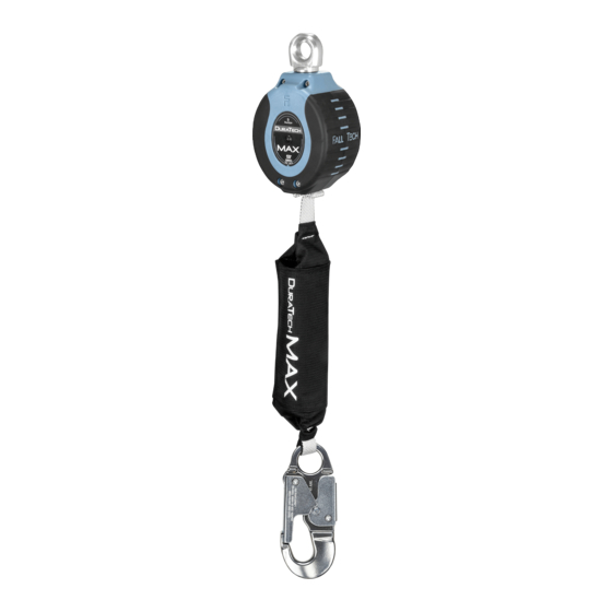
DuraTech® Max 9' Web Single/Twin Self Retracting Device
This manual is intended to meet the Manufacturer's Instructions as required by the American National Standards
Institute (ANSI) Z359 and should be used as part of an employee training program as required by the Occupational
Safety and Health Act (OSHA).
WARNING
This product is part of a personal fall arrest, restraint, work positioning, suspension, or rescue system. A Personal Fall
Arrest System (PFAS) is typically composed of an anchorage and a Full Body Harness (FBH), with a connecting device,
i.e., a Shock Absorbing Lanyard (SAL), or a Self-Retracting Device (SRD), attached to the dorsal D-ring of the FBH.
These instructions must be provided to the worker of this equipment. The worker must read and understand the
manufacturer's instructions for each component or part of the complete system. Manufacturer's instructions must be
followed for proper use, care, and maintenance of this product. These instructions must be retained and be kept
available for the worker's reference at all times. Alterations or misuse of this product, or failure to follow instructions,
may result in serious injury or death.
A Fall Protection Plan must be on file and available for review by all workers. It is the responsibility of the worker and
the purchaser of this equipment to assure that workers of this equipment are properly trained in its use,
maintenance, and storage. Training must be repeated at regular intervals. Training must not subject the trainee to fall
hazards.
Consult a doctor if there is reason to doubt your fitness to safely absorb the shock of a fall event. Age and fitness
seriously affect a worker's ability to withstand falls. Pregnant women or minors must not use this equipment.
ANSI limits the weight of fall protection equipment users to a maximum of 310 lbs. The Self Retracting Device discussed
in this manual is rated for a maximum of 425 lbs. Heavy users experience more risk of serious injury or death due to falls
because of increased fall arrest forces placed on the user's body. In addition, the onset of suspension trauma after a fall
even may be accelerated for heavy users.
NOTE: For more information consult ANSI Z359
User Instruction Manual
FallTech
1306 South Alameda Street
Compton, CA 90221, USA
1-800-719-4619
1-323-752-0066
www.FallTech .com
©
2015
MSRD09.1
090315
Advertisement
Table of Contents

Subscribe to Our Youtube Channel
Related Manuals for Falltech DuraTech Max Web Single


Summary of Contents for Falltech DuraTech Max Web Single
- Page 1 In addition, the onset of suspension trauma after a fall even may be accelerated for heavy users. NOTE: For more information consult ANSI Z359 FallTech 1306 South Alameda Street Compton, CA 90221, USA 1-800-719-4619 1-323-752-0066 www.FallTech .com © 2015 MSRD09.1 090315...
-
Page 2: Table Of Contents
The user of the equipment discussed in this manual must read and understand the entire manual before beginning work. For purposes of this manual, the FallTech® DuraTech® Max 9' Web Single/Twin SRD may be referred to as the Max 9' SRD, the SRD, the equipment, the device, the product, or the unit. -
Page 3: System Requirements
Do not use equipment that is not compatible. Non-compatible connectors may unintentionally disengage. Connectors must be compatible in size, shape, and strength. Self-closing, self-locking snap hooks and carabiners are specified by OSHA and ANSI Z359.12. FallTech offers a wide variety of connectors for use with the 9' SRD. See Table 1-B and Table 1-C. -
Page 4: Personal Fall Arrest System Anchorage Strength
4. INSTALLATION AND USE WARNING Do not alter or intentionally misuse this equipment. Consult FallTech when using this equipment in combination with components or subsystems other than those described in this manual. Do not connect rebar hooks, large carabiners, or large snap hooks to the FBH dorsal D-rings as this may cause a roll-out condition and/or unintentional disengagement. -
Page 5: Installation And Use Of The Srd
A = Added Free Fall Distance Required Due To Non-Overhead Anchorage B = SRD Deceleration Distance C = Additional Deceleration Distance Due To Below D-Ring Attachment D = D-Ring Shift And Harness Stretch E = Safety Factor F = Sub Total- Minimum Required Fall Clearance G = Additional Fall Clearance Distance Due to Swing Fall H = MRFC The MRFC sub-total for a non-overhead anchorage below the D-ring is calculated as A+B+C+D+E = F. -
Page 6: Twin-Leg Srd Work Zone Transition
EA itself. Any torn stitching in the fold accompanied by any expansion or lengthening of the EA is an indication that a fall event has occurred. If you have any questions contact FallTech at info@falltech.com. Inspect the unit before each use in accordance with the instructions in this manual. If any of the above conditions are evident, remove the SRD from service immediately. -
Page 7: Labels
8. LABELS The labels must be present and legible. - Page 8 Además, el inicio del trauma por suspensión después de una caída incluso puede acelerarse para los usuarios pesados. NOTA: Para obtener más información, consulte ANSI Z359 FallTech 1306 South Alameda Street Compton, CA 90221, USA...
- Page 9 El usuario del equipo descrito en este manual debe leer y entender el manual completo antes de comenzar a trabajar. Para los efectos de este manual, el SRD máximo doble/individual DuraTech® de FallTech® con correa de 9 pies (2,7 m) se puede denominar como el SRD máximo de 9 pies (2,7 m), el SRD, el equipo, el dispositivo, el producto o la unidad.
- Page 10 Los conectores deben ser compatibles en tamaño, forma y resistencia. Los mosquetones y ganchos de cierre y bloqueo automático son requeridos por ANSI Z359.12 y la OSHA. FallTech ofrece una amplia variedad de conectores para usar con el SRD de 9 pies (2,7 m).
- Page 11 4. INSTALACIÓN Y USO ADVERTENCIA No altere ni utilice este equipo de manera indebida e intencional. Consulte a FallTech cuando utiliza este equipo en combinación con componentes o subsistemas distintos a los descritos en este manual. No conecte ganchos de refuerzo, mosquetones grandes o ganchos de cierre instantáneo grandes a los anillos en "D" dorsales del FBH, ya que esto puede causar una condición de vuelco y/o la desconexión involuntaria.
- Page 12 4.2 Anclaje: Seleccione un punto de anclaje adecuado. Consulte el párrafo 3.6. En adición a los requisitos de resistencia y carga, considere la altura del anclaje, la distancia entre el anclaje y el anillo en "D" dorsal del FBH del usuario, la distancia entre el anclaje y la superficie para trabajar/caminar, y la distancia entre la superficie para trabajar/caminar y cualquier obstrucción por debajo de ella, incluyendo el nivel inferior o el piso.
- Page 13 ADVERTENCIA Una zona de trabajo ampliada combinada con un SRD utilizado en una condición que no esté por encima del nivel de la cabeza (por debajo del anillo en "D") es extremadamente peligrosa. NO conecte a un anclaje que esté a más de 5 pies (1,5 m) por debajo del nivel del anillo en "D" del FBH. 4.5 Instalación y uso del SRD: Utilice los conectores compatibles para la conexión con el anclaje y asegúrese de que no pueda ocurrir una desconexión involuntaria.
- Page 14 EA. Las costuras rotas en el pliegue junto con la expansión o ampliación del amortiguador es una indicación de que ha ocurrido un evento de caída. Si tiene alguna pregunta, póngase en contacto con FallTech en info@falltech.com.
- Page 16 APPENDIX A Table 1A: Specifications for 9’ Max Web SRDs Minimum SRD Configuration Maximum Standards and Tensile Strength 9’ SRD and Part Numbers User Capacity Regulations and Material Webbing: 4,500 lbs Twin Leg 80% Dyneema SRDs: 20% Polyester 82709TB1 21mm width 82709TB3 310 lbs to Swivel Eye:...
- Page 17 Table 1B: Specifications for Housing Swivel-Eye Connectors Housing Swivel Eye Connector Connector Material Gate Opening Part # Reference Eye: Integral Housing Swivel Eye only Aluminum .67” Triple-lock Carabiner with Alignment Clip .55” Steel Above Carabiner has a 5,000lb Minimum Tensile Strength and 3,600lb Gate Strength to comply with ANSI Z359.12 Carabiner and Clip used to join two Single Leg SRD’s into one Twin Leg unit.
- Page 18 Tabla 1B: Las especificaciones de los conectores con ojal de oscilación y carcasa Referencia de Conector con ojal de Apertura del Conector Material pestillo No. de parte oscilación de carcasa Ojal: Sólo ojal de oscilación Aluminio integral de la carcasa .67”...
- Page 19 Table 1D: 9’ Max Web SRDs- Typical FallTech Performance Attributes and ANSI Performance Requirements FallTech Maximum Values of Testing ANSI Perfomance Requirements Average Maximum Maximum User Arrest Maximum Average Arrest Arrest Force Arrest Condition Distance Arrest Force Arrest Force Distance...
- Page 20 Table 1E: 9’ Max Web SRDs with Connector Reference Housing Swivel Leg-End Connectors Eye Connectors Retracted Extended Single Leg Part #s Weight Length Length 82709SA1 1’ 9” 8’ 11” 3.3 lbs 82709SA3 2’ 1” 9’ 3” 4.2 lbs 82709SA4 1’ 9” 8’...
- Page 21 Table 2: ANSI Z359.14 SRD Inspection Requirements Application Inspection Frequency Type of Use Conditions of Use Examples Competent Person Good Storage Conditions, Rescue and Indoor or Infrequent Infrequent to Confined Space, Outdoor Use, Room Annually Light Use Factory Maintenance Temperature, Clean Environments Fair Storage Conditions, Transportation,...
- Page 22 Table 3: Guidelines for Web SRD Inspection (use Figure 1 where needed) Inspection Pass Fail The web lifeline should extract and retract completely and without faltering and should remain taut under tension without sagging. Extract the web lifeline several inches and apply a firm pull to confirm the SRD locks.
- Page 23 Tabla 3: Directrices para la inspección del SRD con cordón (utilice la Figura 1 donde sea necesario) Inspección Aprobado Fallado La cuerda de salvamento con correa se debe extraer y retraer por completo y sin fallar y debe seguir estando tensa bajo tensión sin aflojarse.
- Page 24 Figure 1: About 9’ Max Web SRDs Leg-end Connector Integral Swivel Eye Triple-lock Carabiner Unit Housing Alignment Clip Load Indicator Stitch Triple-Lock Gate Web Lifeline Max Energy Absorber Figura 1: Acerca de los SRD máximo con correa de 9 pies (2,7 m) Conector del extremo de Ojal de oscilación integral la pierna...
- Page 25 Figure 2A: 9’ Max Web SRD Orientation and Acceptable Anchorage Range 9’ Single-leg Attached to Dorsal D-ring Shaded area indicates Range of Allowable Connection from: Directly Overhead to as low as 5’ Below User’s Dorsal D-ring Figure 2B: 9’ Max SRD Orientation and Acceptable Anchorage Range 9’...
- Page 26 Figura 2A: Orientación del SRD máximo con correa de 9 pies (2,7 m) y rango aceptable del anclaje SRD individual de 9 pies (2,7 m) conectado al anillo en “D” dorsal el área sombreada indica el Rango permisible de conexión desde: Directamente por encima de la cabeza a tan bajo como a 5 pies (1,5 m) por debajo del anillo en “D”...
- Page 27 310 lbs Maximum User Capacity Overhead Anchorage Figure 3A: 9’ Max Web SRD Minimum Required Fall Clearance SRD Deceleration Distance 4½ ft 1 ft D-ring Shift and Harness Stretch 1½ ft Safety Factor Sub Total- Minimum Required Fall Clearance 7 ft for direct overhead use of SRD with No Swing Fall (sum of A, B and C only) *Additional Fall Clearance Calculation due to Swing Fall (using Chart 1)
- Page 28 Capacidad máxima del usuario de 310 Anclaje por encima del nivel de la cabeza libras (140,6 kg) Figura 3A: Distancia mínima de caída despejada requerida para SRD máximo con correa de 9 pies (2,7 m) 4½ pies Distancia de desaceleración del SRD (1,4 m) 1 pie (0,3 Cambio del anillo en “D”...
- Page 29 310 lbs Maximum User Capacity Non-Overhead Anchorage Figure 3B: 9’ Max Web SRD Minimum Required Fall Clearance 5 ft Free Fall Distance due to Below D-ring Anchorage SRD Deceleration Distance 4½ ft 6½ ft Additional Deceleration due to below D-ring Attachment 1 ft D-ring Shift and Harness Stretch 1½...
- Page 30 Capacidad máxima del usuario de 425 Anclaje que no está por encima del nivel de libras (192,8 kg) la cabeza Figura 3B: Distancia mínima de caída despejada requerida para SRD máximo con correa de 9 pies (2,7 m) 5 pies Distancia de caída libre debido al anclaje por debajo del anillo en “D”...
- Page 31 425 lbs Maximum User Capacity Overhead Anchorage Figure 4A: 9’ Max Web SRD Minimum Required Fall Clearance SRD Deceleration Distance 5½ ft 1 ft D-ring Shift and Harness Stretch 1½ ft Safety Factor Sub Total- Minimum Required Fall Clearance 8 ft for direct overhead use of SRD with No Swing Fall (sum of A, B and C only) *Additional Fall Clearance Calculation due to Swing Fall (using Chart 1)
- Page 32 Capacidad máxima del usuario de Anclaje por encima del nivel de la cabeza 425 libras (192,8 kg) Figura 4A: Distancia mínima de caída despejada requerida para SRD máximo con correa de 9 pies (2,7 m) 5½ pies Distancia de desaceleración del SRD (1,7 m) 1 pie Cambio del anillo en “D”...
- Page 33 425 lbs Maximum User Capacity Non-Overhead Anchorage Figure 4B: 9’ Max Web SRD Minimum Required Fall Clearance 5 ft Free Fall Distance due to Below D-ring Anchorage 5½ ft SRD Deceleration Distance 8 ft Additional Deceleration due to below D-ring Attachment 1 ft D-ring Shift and Harness Stretch 1½...
- Page 34 Capacidad máxima del usuario de Anclaje que no está por encima del nivel 425 libras (192,8 kg) de la cabeza Figura 4B: Distancia mínima de caída despejada requerida para SRD máximo con correa de 9 pies (2,7 m) 5 ft Distancia de caída libre debido al anclaje por debajo del anillo en “D”...
- Page 35 Figure 5A: Swing Fall Hazards for Overhead Anchorage Overhead Anchorage 9’ Max Single-leg Self-Retracting Device Walking/Working Surface Swing Fall Impact After Fall Event Next Lower Level or Obstruction See Chart 1 for additional Swing Fall hazard due to increased Fall Distance Figura 5A: Peligros de caída con balanceo para anclaje que está...
- Page 36 Chart 1: Additional Required Fall Clearance Due to Swing Fall (ft) 6’ 6’ 6’ 6’ 6’ 9’ 6’ 6’ 6’ 6’ 6’ 0’ 0’ 0’ 0’ 0’ 6’ 6’ 0’ 0’ 6’ 6’ 6’ 8’ 6’ 6’ 6’ 6’ 6’ 0’...
- Page 37 Gráfico 1: Distancia de caída despejada adicional requerida debido a la caída con bal- anceo (pies/metros) 6’ 6’ 6’ 6’ 6’ 9’ 6’ 6’ 6’ 6’ 6’ 0’ 0’ 0’ 0’ 0’ 6’ 6’ 0’ 6’ 6’ 6’ 6’ 6’ 0’...
- Page 38 Figure 6A: Attaching Single-leg Max SRD to FBH Anchorage Leg End Connector External Energy Absorber Web Lifeline SRD Body/Housing SRD Integral Swivel Eye Connecting Carabiner Dorsal D-ring on FBH Figura 6A: Conectar un SRD máximo individual a un FBH Anchorage Leg End Connector External Energy Absorber Web Lifeline...
- Page 39 Figure 7A: Attaching Twin-leg SRD to FBH 1. Prepare Twin-leg SRD for Attachment 2. Prepare FBH and Preliminary Attachment 2. Prepare FBH and Preliminary Attachment: (E) Lift the Dorsal D-ring to the up-pointing position then loosen the intersection of the two web straps that pass through the D-ring slot to create slacked loops of about 2”...
- Page 40 Instalación de SRD doble con sujeción trasera Figure 7A: de 9 pies (2,7 m) al anillo en “D” dorsal 1. Preparar el SRD doble para la conexión 2. Preparación del FBH y conexión preliminar 2. Preparación del FBH y conexión preliminar: (E) Levante el anillo en “D”...
- Page 41 INCORRECT INCORRECT INCORRECT INCORRECT CORRECT Figure 7B: Incorrect Twin-leg SRD Attachment DO NOT Attach directly to the Dorsal D-ring DO NOT Attach to only one of the intersecting web straps DO NOT Attach to intersecting web straps over/above the Dorsal D-ring DO NOT Attach anywhere outside the intersecting web straps CORRECT attachment to both intersecting web straps with Dorsal D-ring in the up position...
- Page 42 Before Lateral Movement Starting Lateral Movement Momentary Transition Ending Lateral Movement After Lateral Movement Figure 8: Use of Twin-leg Max SRDs for Lateral Movement Orginal Work Location before lateral movement Starting lateral movement; one leg connected to Anchor During lateral move; both legs connected in momentary transition between Anchors Ending lateral movement;...
- Page 43 APPENDIX B Fig. 1 - Minimum Clear Fall Requirement: 6 ft Shock Absorbing Lanyard Measured from Overhead Anchorage Connector Length of Shock Absorbing Lanyard 6 ft Original working length before a fall event occurs/before activation of energy absorber Elongation/Deceleration Distance 4 ft Maximum allowable amount of elongation that may payout from the energy absorber upon activation during a fall event...
- Page 44 Fig. 3 - Minimum Clear Fall Requirement: ANSI Class A Self-Retracting Device Activation/Deceleration Distance 2 ft Maximum allowable length of cable or web that may payout from the SRD once deceleration of the user has begun and after a fall event occurs Harness Stretch and Dorsal D-Ring Shift 1 ft Combined amount of harness webbing elongation and dorsal D-ring up-...
- Page 45 Fig. 5 - Managing Stretch Minimum Clear Fall Requirement: Vertical Lifeline System Stretch of Vertical Lifeline Stretch Stretch = length of VLL from Anchorage Connector to Rope Grab position on VLL multiplied by 10% Length of Shock Absorbing Lanyard 3 ft Original working length before a fall event occurs/before activation of energy absorber Elongation/Deceleration Distance...
- Page 46 Common Fall Protection Applications Fig. 7 - Fall Arrest (PFAS) Fig. 8 - Work Positioning Anchorage Positioning Anchor Anchorage Connector Positioning Lanyard Full Body Harness (FBH) with Shock Absorbing Lanyard (SAL) Side D-Rings Full Body Harness (FBH) Back-up Fall Arrest (PFAS) Walking/Working Surface Fig.
-
Page 47: Inspection Record
Incorrect Connections / Acronyms for Fall Protection and Fall Arrest / Inspection Record Fig. 13 - Incorrect Connections Fig. 13 - Conexiones incorrectas Never connect two active components (snap hooks or carabiners) Nunca conecte dos componentes activos (ganchos de cierre instantáneo to each other.
Need help?
Do you have a question about the DuraTech Max Web Single and is the answer not in the manual?
Questions and answers