
Related Manuals for CAMPAGNOLO Ekar RD21


Summary of Contents for CAMPAGNOLO Ekar RD21
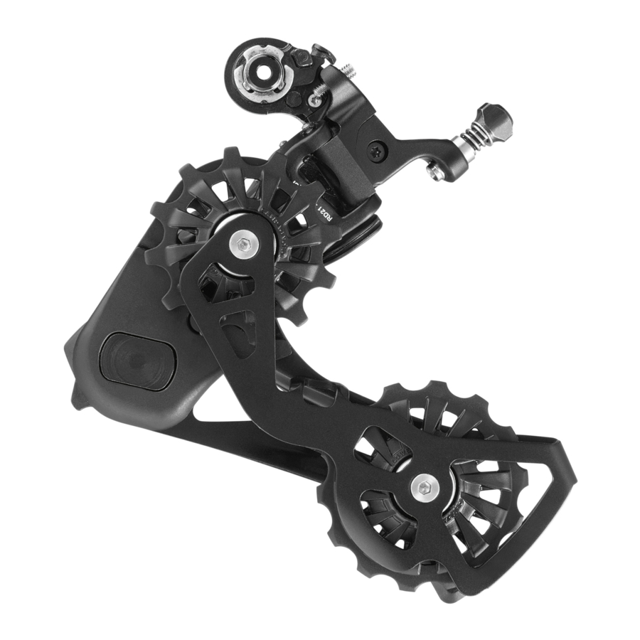
- Page 1 R E PL A C I N G T HE J O CKE Y C AGE OF THE R E A R D ER A ILLEU R (RD21- EK 13) C A M PA G N O L O. CO M...
- Page 2 WARNING! Always wear protective gloves and glasses while working on the bicycle. R EPL ACIN G T HE J O CK E Y CA GE - Rev. 0 1 / 0 6 - 2 0 2 1 CA M PA G NO L O C O M PO NE NT S - T E C H NIC A L M A NUA L...
- Page 3 FIXED WRENCH FIXED WRENCH 8 mm 30 mm 8 mm 8 mm Tools supplied by other manufacturers for components similar to Campagnolo components, may ® not be compatible with Campagnolo components. Likewise, tools supplied by Campagnolo s.r.l. ® may not be compatible with components supplied by other manufacturers. Always check with your mechanic or the tool manufacturer to insure compatibility before using tools supplied by one manu- facturer on components supplied by another.
- Page 4 1) Grasp the body and rotate the jockey cage anti-clockwise until the screw is visible (A - Fig.1). 2) Keeping the jockey cage locked, remove the screw (A - Fig.2). WARNING! Left-hand thread. Fig.1 Fig.2 3) Accompany the jockey cage until the spring is completely unloaded (Fig.
- Page 5 5) Remove the jockey cage fixing nut (Fig.6 / Fig.7). 8 mm Fig.6 Fig.7 6) Use a T15 Torx wrench to remove the nut on the jockey cage side, acting on the clutch shaft (Fig.8 / Fig.9). Fig.8 Fig.9 7) Remove the jockey cage and the sealing ring (Fig.
- Page 6 WARNING! Campagnolo spare parts must only be installed by qualified personnel with specialised knowledge, suitable tools and sufficient experience and who carefully follow the installation instructions. Failure to comply with the above could result in product malfunctions, accidents, physical injury or death.
- Page 7 1) Insert the sealing ring, making sure it is positioned correctly (Fig.1). Fig.1 2) Apply “Loctite 2701” (Fig.2) to the clutch shaft. Fig.2 3) Install the jockey cage, hooking the spring in the corresponding hole on the jockey cage itself (Fig. 3). Fig.3 4) Install the nut on the jockey cage side by 8 Nm...
- Page 8 5) Apply “Loctite 2701” (Fig. 6) to the jockey cage fixing nut. Fig.6 6) Install the jockey cage fixing nut (Fig.7 / 2,5 Nm Fig.7). Tighten to a torque of 2.5 Nm (Fig.8). WARNING! Observe the tightening torque. A higher tightening torque could damage the components inside the rear derailleur, causing it to malfun- ction.
- Page 9 10) Load the spring by turning the jockey cage ONE (360°) complete turn 360° counterclockwise (Fig. 12). WARNING! The rear derailleur is spring-loaded and will quickly return to its starting position. Pay special attention when accom- panying the jockey cage and keep your fingers well away from points at risk of crushing.
Need help?
Do you have a question about the Ekar RD21 and is the answer not in the manual?
Questions and answers