Advertisement
Quick Links
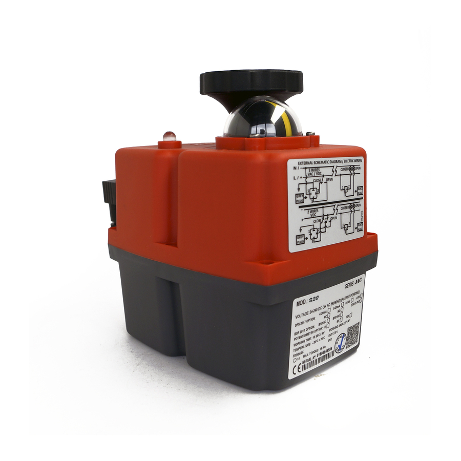
ASSEMBLY INSTRUCTIONS J4C 20/85
PIECES
A
- 1 Cover
B
- 1 Plastic column
C
- 1 DPS positioner PCB
D
- 2 Sheet metal Fixing screws
E
- 1 Plastic Fixing screws
PREPARING THE COVER:
The cover of the kit is for a J4C-20, 35 and 55 models. In case you want to mount a kit on a J4C85,
follow the instructions:
Remove the
cap and leave
the o-ring
inside the hole
cap
O-ring
PLEASE READ CAREFULLY BEFORE MOUNTING.
VERY IMPORTANT!!!! PLEASE FOLLOW THE INSTRUCTIONS STEP BY STEP. BEFORE CON-
NECTING "A" PLUG TO THE ACTUATOR,
CHECK THAT THE VOLTAGE IS THE SAME AS THE ONE SPECIFIED ON THE LABEL (CARTER).
TO CONVERT A STANDARD (ON-OFF) J4C ELECTRIC ACTUATOR INTO A MODULATING
FUNCTION WITH POSITIONER, PROCEED AS FOLLOWS:
A
1
A B
Remove the
sleeve 1 and
leave the
Oring inside.
sleeve
O-ring
MOUNTING INSTRUCTIONS J4C 20/85
B
C
Introduce the
sleeve in hole
A and press it
until is fully
inside(Fig.A)
sleeve
Introd uce the
cap in hole B
and press it
until it is fully
inside (Fig.B)
cap
D
E
Advertisement

Related Manuals for J+J J4C 20


Summary of Contents for J+J J4C 20
- Page 1 MOUNTING INSTRUCTIONS J4C 20/85 ASSEMBLY INSTRUCTIONS J4C 20/85 PIECES - 1 Cover - 1 Plastic column - 1 DPS positioner PCB - 2 Sheet metal Fixing screws - 1 Plastic Fixing screws PREPARING THE COVER: The cover of the kit is for a J4C-20, 35 and 55 models. In case you want to mount a kit on a J4C85,...
- Page 2 MOUNTING INSTRUCTIONS J4C 20/85 ASSEMBLY INSTRUCTIONS J4C 20/85 The unit must be disconnected from any electrical power or signal before installing. 1. Remove the screw, which is fixing the hand wheel. (Fig. 2) 2. Remove the 6 screws, which are fixing the body to the cover of the actuator (Fig.3).
- Page 3 MOUNTING INSTRUCTIONS J4C 20/85 ASSEMBLY INSTRUCTIONS J4C 20/85...
- Page 4 MOUNTING INSTRUCTIONS J4C 140/300 ASSEMBLY INSTRUCTIONS J4C 140/300 PIECES - 1 Cover - 1 Plastic column - 1 DPS positioner PCB - 2 Sheet metal Fixing screws - 1 Plastic Fixing screws - 1 Schematic iagram la el PLEASE READ CAREFULLY BEFORE MOUNTING. VERY IMPORTANT!!!! PLEASE FOLLOW THE INSTRUCTIONS STEP BY STEP.
- Page 5 MOUNTING INSTRUCTIONS J4C 140/300 ASSEMBLY INSTRUCTIONS J4C 140/300 14. Disconnect the grey connector from the power supply. 15. Use the configuration you need by moving the DIPs, according to the instrumentation signal (Fig.14): 16. Care- fully mount the cover, minding the cables not to be pressed (Fig.15). 17.
- Page 6 MOUNTING INSTRUCTIONS J4C 140/300 ASSEMBLY INSTRUCTIONS J4C 140/300...
Need help?
Do you have a question about the J4C 20 and is the answer not in the manual?
Questions and answers