Advertisement
Quick Links
.
J3C TYPE ELECTRIC ACTUATOR TROUBLESHOOTING GUIDE
WHAT THIS GUIDE IS, AND HOW TO USE IT
This comprehensive document provides POSSIBLE SOLUTIONS and/or ADVICE for reported
'faulty' actuators, and is intended purely as a guide to identify possible causes and
remedies for actuators that are not working as expected.
• Use the index to identify the page in the document most likely to help.
• When a user sends a command signal to an actuated valve and it doesn't respond, it is
usually automatically assumed that the actuator is faulty. In practice, in most cases, the
fault is either with the valve, or with the electrical system controlling the actuator, and
not the actuator itself.
• This document is intended to help identify where the problem is. J+J are not qualified
electrical, electronic or control engineers and therefore 'POSSIBLE SOLUTIONS/ ADVICE'
contained in this document are only suggestions and recommendations based on 20 years
of practical experience.
• The warranty on the J3C S Type electric actuator relates to the product itself, and does
not extend beyond those parts supplied. All external equipment/ wiring/ influences are
provided by, and are the sole responsibility of, the customer.
• Errors & omissions excluded and subject to correction when identified.
INDEX
Page No
Symptom or description
1
How to use this guide & Index
2
LED light
3
LED not lit, actuator doesn't work
4
LED lit solidly but actuator doesn't work
4
LED flashing and actuator doesn't work
5 & 6
Electronic Torque Limiter engaged
7 & 8
Manual Override Engaged
9
LED flashing when the actuator is NOT fitted to valve
10 & 11
PCB Issues
11
Actuator drives continuously
12
Failsafe function issues (BSR installed)
13
Modulating function/ positioner issues (DPS installed)
14
Modulating function/ positioner soft reset
14 & 15
Modulating function/ positioner fault finding
16
DIN plug issues
17
Housing Issues
18
Most common causes of 'malfunctions'
18
Information needed to report a 'faulty' actuator
Page 1 of 18
Advertisement

Subscribe to Our Youtube Channel
Related Manuals for J+J J3C


Summary of Contents for J+J J3C
- Page 1 Failsafe function issues (BSR installed) Modulating function/ positioner issues (DPS installed) • The warranty on the J3C S Type electric actuator relates to the product itself, and does not extend beyond those parts supplied. All external equipment/ wiring/ influences are Modulating function/ positioner soft reset provided by, and are the sole responsibility of, the customer.
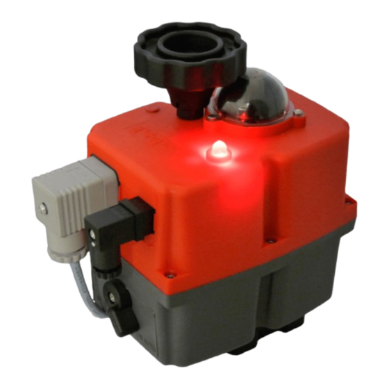
- Page 2 LED Status Light - using it as a diagnostic tool: The LED is provided as standard to give users a continuous visual feedback of the functional status of the actuator. • If the LED is not lit the actuator is not receiving, or seeing external power at the grey DIN (power) plug. •...
- Page 3 LED NOT LIT, ACTUATOR DOESN’T WORK REPORTED FAULT POSSIBLE REASON(S) POSSIBLE SOLUTIONS/ ADVICE LED not lit No external power • Check wiring AT THE ACTUATOR’s GREY DIN PLUG matches the wiring on the actuator’s wiring diagram (affixed to actuator). arriving at the •...
- Page 4 LED LIT SOLIDLY BUT ACTUATOR DOESN’T WORK REPORTED FAULT POSSIBLE REASON(S) POSSIBLE SOLUTIONS/ ADVICE LED lit solid but Wiring issue • Check wiring as above. actuator not working • Ensure that in on-off versions, a signal is not being sent to both ‘live’ pins (2 & 3) at the same time Signalling issue •...
- Page 5 Whilst the ETL protects the gearbox from mechanical damage caused by a valve blockage, if the blockage is not investigated and the actuator’s ETL is activated excessively (this can be identified from the electronic counters that can be read by J+J service centres, comparing torque limiter activations to number of operations), it is possible that eventually the gearbox will fail mechanically.
- Page 6 Models J3C-20-S85 (H/L Series) use a brushed DC motor. Brushed motors are susceptible to carbon brush wear which can result in a build-up of carbon brush dust. In older J+J actuators where the motor is not fitted with a dust cap, this dust covers all internals in high...
- Page 7 ② MANUAL OVERRIDE ENGAGED REPORTED FAULT POSSIBLE REASON(S) POSSIBLE SOLUTIONS/ ADVICE LED Flashing Manual override is Manual Override (MO) activated selected Description of MO function: When ‘MAN’ is selected, the motor continues to run and starts a timer in the processor but the actuator’s output drive is disconnected from the drive train.
- Page 8 down next to, and ‘AUTO’ does not engage. This is corrected by either (a) manually operating the override lever or hand-wheel backwards and forwards (wiggling it!) until the spring pushes the gear back down – you can generally hear a click when this happens, or (b) by applying a reversing signal to the actuator which will cause the gear to automatically drop back into place.
- Page 9 LED FLASHING WHEN ACTUATOR NOT FITTED TO VALVE REPORTED FAULT POSSIBLE REASON(S) POSSIBLE SOLUTIONS/ ADVICE LED Flashing when Motor issue This generally indicates a motor issue. the actuator is not • Motor issues generally cause increased or erratic current draw which can activate the ETL as it mimics the effect of a jammed valve – the fitted to the valve actuator can therefore activate the ETL (and causing the LED to flash) even if it is not fitted to a valve.
- Page 10 ‘track’ can be seen. • The J3C is fully weatherproof to IP67 and under normal circumstances does not have any issues with water (or dust) ingress. It cannot however be submerged for long periods, hosed down, deluged in water, or pressure washed.
- Page 11 PCB related. In doing so, the motor is irreparably damaged (and also possibly the main PCB if the motor cable is not removed from the PCB ahead of the ‘test’) because all J3C-S actuators use a 24VDC motor.
- Page 12 FAILSAFE (BSR) ISSUES REPORTED FAULT POSSIBLE REASON(S) POSSIBLE SOLUTIONS/ ADVICE Actuator doesn’t Incorrectly installed Note: ALWAYS test the actuator into which the BSR is going to be installed as an on-off actuator BEFORE installing the BSR, this confirms work after installing that the actuator is working before the function conversion, and that the supply voltage and wiring connections are correct.
- Page 13 MODULATING (DPS) – INSTALLATION ISSUES REPORTED FAULT POSSIBLE REASON(S) POSSIBLE SOLUTIONS/ ADVICE DPS won’t set up Incorrect installation Notes: • ALWAYS test the actuator as an on-off actuator into which the DPS is going to be installed BEFORE installing the DPS, this confirms that the actuator is working correctly before the function conversion.
- Page 14 DPS POSITIONER SOFT RESET REPORTED FAULT POSSIBLE REASON(S) POSSIBLE SOLUTIONS/ ADVICE DPS not responding Lost calibration, • Remove power accurately to input software locked up/ signals • Remove control signal Din plug (centre plug) looping in micro-chip • On the control Din plug base, create a short circuit between pin 3 (at 6 ’ clock position) and pin 1 (at 3 o’ clock position). •...
- Page 15 Common causes of electrical interference: • Voltage surge, voltage drops, voltage spikes, line faults (damaged cable, bad connections). • Close proximity to electronic equipment, and/or to power source. • Noisy motors, relay ‘chatter’. • Poor dead-band control in process controller providing the signal to the DPS Suggested remedies: •...
- Page 16 DIN PLUG ISSUES REPORTED FAULT POSSIBLE REASON(S) POSSIBLE SOLUTIONS/ ADVICE Common Din plug Wiring issues Incorrect wiring. issues • Check wiring diagram to confirm that the right cable is connected to the right pin. • The power connection is grey (pug and base) with neutral in pin 1 and a switchable live between pins 2 (to close) and 3 (to open), •...
- Page 17 HOUSING ISSUES REPORTED FAULT POSSIBLE REASON(S) POSSIBLE SOLUTIONS/ ADVICE Common housing Ingress Protection Issues: issues • The actuator has been hosed down, pressure washed, or located where a tank can overflow and deluge the actuator in water. The actuator has an ingress protection rating of IP67 which allows it to be submerged to a maximum of 1m for 30 minutes, but does not offer protection against any form of pressurised wash down.
- Page 18 MOST COMMON CAUSES OF ‘MALFUNCTION’ • Actuator is in ‘MANUAL’ mode • Valve is jammed and actuator’s electronic torque limiter has engaged • Incorrectly sized actuator for the application • Incorrect wiring • Incorrect power supply • Incorrect command signal/ Poor quality of control signal in modulating applications INFORMATION NEEDED WHEN REPORTING A ‘FAULTY’...
Need help?
Do you have a question about the J3C and is the answer not in the manual?
Questions and answers