Advertisement
Quick Links
Advertisement

Related Manuals for J+J J4M Series


Summary of Contents for J+J J4M Series
- Page 1 HANDBOOK www.jjbcn.com Handbook (EN) 23-03 V1...
- Page 2 04. Bluetooth Interface Manual • S2, S6, S10, B2, B6, B10 › 05. Option • S25, S40, B25, B40 • Modbus › 02. J4M series › 06. Guarantee • Voltage › 07. Contact • Electrical Connectors • ID Actuator Label •...
-
Page 3: Part List
01 ACTUATOR PART LIST Index... - Page 4 HANDBOOK / ACTUATOR PART LIST MODELS: S2, S6, S10, B2, B6, B10 Manual override Position indicator Visual control of operation Signal plug Power supply plug Volt free contact plug Automatic/ ISO multiflange manual lever Index...
- Page 5 HANDBOOK / ACTUATOR PART LIST MODELS: S25, S40, B25, B40 Manual override Visual control of Position indicator operation Power supply plug Signal plug Volt free contact plug ISO multiflange Automatic/ manual lever Index...
- Page 6 02 J4M SERIES Index...
-
Page 7: Electrical Connectors
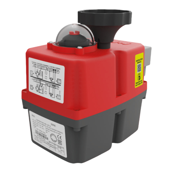
HANDBOOK / J4M SERIES Read these instructions before connecting the actuator. Damage caused by non compliance of these instructions is not covered by our warranty. J4M Electric actuators operate with the use of live electricity. It is recommended that only qualified electrical engineers be allowed to connect or adjust these actuators. - Page 8 HANDBOOK / J4M SERIES ID ACTUATOR LABEL Actuator Model. Actuator series. Voltage to be connected. Duty: 75%. Actuator ready to bear between -20ºC / +70ºC. QR code for manufacturing. Time/Turn. Actuator with CE certificate. Working angle. This product should not be disposed of as unsorted waste.
- Page 9 HANDBOOK / J4M SERIES LOCAL VISUAL POSITION INDICATOR All J4M actuators are supplied with a local visual position indicator (Fig.6). The OPEN position shows the indicator in BLACK and at the end of the stroke (max 14 turns) shows the full indicator in RED.
- Page 10 HANDBOOK / J4M SERIES Fig. 7 J4M 2,6 and 10 Fig. 7 J4M 25 and 40 J4M 2,6 and 10 J4M 25 and 40 Hand Wheel Position Indicator Automatic - Manual When “MAN” function is selected: The electronic system cuts the power to the motor after a few minutes.
- Page 11 HANDBOOK / J4M SERIES TABLE OF CONSUMPTIONS ON-OFF ACTUATOR J4M S2 Consumption Minimum operational torque - 2 Nm Maximum operational torque - 5,5 Nm Voltage Model 12 VDC 1,62 19,50 2,17 26,00 24 VDC 0,81 19,30 1,28 30,70 48 VDC...
- Page 12 HANDBOOK / J4M SERIES TABLE OF CONSUMPTIONS ON-OFF ACTUATOR J4M S25 Consumption Minimum operational torque - 10 Nm Maximum operational torque - 30 Nm Voltage Model 12 VDC 3,08 37,00 7,46 89,60 24 VDC 2,20 52,90 3,53 84,70 48 VDC...
- Page 13 HANDBOOK / J4M SERIES EXTERNAL CONNECTING DIAGRAM ON - OFF VAC / VDC The power supply is connected to the grey “A” DIN plug. • Neutral or negative PIN 1 + Phase or positive PIN 2 = Actuator close • Neutral or negative PIN 1 + Phase or positive PIN 3 = Actuator open •...
- Page 14 HANDBOOK / J4M SERIES POSITIONER VAC / VDC ONLY OUTPUT The power supply is connected to the grey “A” DIN plug • Neutral/negative PIN 1 + Phase/positive PIN 2 = Close position • Neutral/negative PIN 1 + Phase/positive PIN 3 = Open position •...
-
Page 15: Data Sheet
03 DATASHEET Index... - Page 16 HANDBOOK / DATASHEET J4M 2 J4M 2 - GENERAL CHARACTERISTICS Technical Data Operation time unload 4 Sec / turn Minimum operational torque 2 Nm / 17,70 lb/in Maximum operational torque 5,5 Nm / 48,68 lb/in Duty rating Maximum number turns 13.5 Electronic Data Confirmations...
- Page 17 HANDBOOK / DATASHEET J4M 2 J4M 2 SIZES Index...
- Page 18 HANDBOOK / DATASHEET J4M 2 EXPOLDED VIEW MV J4S02 NÚMERO CÓDIGO CANTIDAD NÚMERO CÓDIGO CANTIDAD NÚMERO CÓDIGO CANTIDAD AP01357 AP01028 AP01194 AP00159 AP00070 AP01023 AP00161 AP00057 AP01056 AP01047 AP00048 AP00911 AP01361 AP01195 AP01000 AP00704 AP01183 AP01106 MM01369 AP00080 MM00699 AP00376 AP01198 AP01017 AP01199...
- Page 19 HANDBOOK / DATASHEET J4M 2 EXPOLDED VIEW MV J4S2 NÚMERO CÓDIGO CANTIDAD NÚMERO CÓDIGO CANTIDAD AP00794 AP01115 AP01013 AP00312 AP00991 AP00251 AP01000 AP00960 AP00014 AP00343 AP00021 AP00031 AP00998 AP00032 AP00861 Index...
- Page 20 HANDBOOK / DATASHEET J4M 2 EXPOLDED VIEW MV J4S2 NÚMERO CÓDIGO CANTIDAD NÚMERO CÓDIGO CANTIDAD NÚMERO CÓDIGO CANTIDAD AP00162 AP00455 MM00091 AP00083 AP00050 AP01098 AP00053 AP00044 AP01099 AP00345 MM00187 AP00068 AP00346 AP00067 AP00037 AP01002 AP00372 AP00457 AP00054 AP01001 AP00023 AP01003 AP00133 AP00056 AP00379...
- Page 21 HANDBOOK / DATASHEET J4M 6 J4M 6 - GENERAL CHARACTERISTICS Technical Data Operation time unload 3 Sec / turn Minimum operational torque 5 Nm / 44,25 lb/in Maximum operational torque 9 Nm / 79,66 lb/in Duty rating Maximum number turns 13.5 Electronic Data Confirmations...
- Page 22 HANDBOOK / DATASHEET J4M 6 J4M 6 SIZES Index...
- Page 23 HANDBOOK / DATASHEET J4M 6 EXPOLDED VIEW MV J4S6 NÚMERO CÓDIGO CANTIDAD NÚMERO CÓDIGO CANTIDAD NÚMERO CÓDIGO CANTIDAD AP01357 AP01028 AP01194 AP00159 AP00070 AP01023 AP00161 AP00057 AP01083 AP01047 AP00048 AP00911 AP01361 AP01195 AP01000 AP00704 AP01183 AP01106 MM01369 AP00080 MM00699 AP00376 AP01198 AP01199 AP01017...
- Page 24 HANDBOOK / DATASHEET J4M 6 EXPOLDED VIEW MV J4S6 NÚMERO CÓDIGO CANTIDAD NÚMERO CÓDIGO CANTIDAD AP00014 AP01115 AP00998 AP00834 AP00794 AP00 655 AP00991 AP00960 AP01000 AP00021 AP01013 AP00032 AP00343 AP00031 AP00145 Index...
- Page 25 HANDBOOK / DATASHEET J4M 6 EXPOLDED VIEW MV J4S6 NÚMERO CÓDIGO CANTIDAD NÚMERO CÓDIGO CANTIDAD NÚMERO CÓDIGO CANTIDAD AP00162 AP00455 MM00091 AP00050 AP01098 AP00083 AP00044 AP01099 AP00053 AP00345 MM00187 AP00068 AP00346 AP00037 AP00067 AP01002 AP00372 AP00457 AP01001 AP00133 AP00054 AP01003 AP00023 AP00056 AP00379...
- Page 26 HANDBOOK / DATASHEET J4M 10 J4M 10 - GENERAL CHARACTERISTICS Technical Data Operation time unload 12,8 Sec. / turn Minimum operational torque 7 Nm / 61,96 lb/in Maximum operational torque 15 Nm / 132,76 lb/in Duty rating Maximum number turns 13.5 Electronic Data Confirmations...
- Page 27 HANDBOOK / DATASHEET J4M 10 J4M 10 SIZES Index...
- Page 28 HANDBOOK / DATASHEET J4M 10 EXPOLDED VIEW MV J4S10 NÚMERO CÓDIGO CANTIDAD NÚMERO CÓDIGO CANTIDAD NÚMERO CÓDIGO CANTIDAD AP01357 AP01028 AP01194 AP00159 AP00070 AP01023 AP00161 AP00057 AP01083 AP01047 AP00048 AP00911 AP01361 AP01195 AP01000 AP00704 AP01183 AP01106 MM01369 AP00080 MM00699 AP00376 AP01198 AP01017 AP01199...
- Page 29 HANDBOOK / DATASHEET J4M 10 EXPOLDED VIEW MV J4S10 NÚMERO CÓDIGO CANTIDAD NÚMERO CÓDIGO CANTIDAD AP00794 AP00031 AP01013 AP00950 AP00991 AP00143 AP01000 AP00014 AP00928 AP00974 AP00955 AP00960 AP00861 AP00021 AP00032 AP00145 AP00343 Index...
- Page 30 HANDBOOK / DATASHEET J4M 10 EXPOLDED VIEW MV J4S10 NÚMERO CÓDIGO CANTIDAD NÚMERO CÓDIGO CANTIDAD NÚMERO CÓDIGO CANTIDAD AP00162 AP00455 MM00091 AP00050 AP01098 AP00083 AP00053 AP00044 AP01099 AP00345 MM00187 AP00068 AP00346 AP00037 AP00067 AP01002 AP00372 AP00457 AP01001 AP00023 AP00054 AP01003 AP00133 AP00056 AP00379...
- Page 31 HANDBOOK / DATASHEET J4M 25 J4M 25 - GENERAL CHARACTERISTICS Technical Data Operation time unload 9,3 Sec / turn Minimum operational torque 10 Nm / 88,51 lb/in Maximum operational torque 30 Nm / 265,52 lb/in Duty rating Maximum number turns 13.5 Electronic Data Confirmations...
- Page 32 HANDBOOK / DATASHEET J4M 25 J4M 25 SIZES Index...
- Page 33 HANDBOOK / DATASHEET J4M 25 EXPOLDED VIEW MV J4S25 NÚMERO CÓDIGO CANTIDAD NÚMERO CÓDIGO CANTIDAD NÚMERO CÓDIGO CANTIDAD AP01370 MM00977 AP01224 AP01126 AP00492 AP01180 AP00159 AP01084 AP00423 AP00161 AP01195 AP00911 AP00080 AP00291 AP01183 AP00698 AP01194 AP00059 MM01369 AP00008 AP01198 AP01199 MM00699 AP00964 AP01108...
- Page 34 HANDBOOK / DATASHEET J4M 25 EXPOLDED VIEW MV J4S25 NÚMERO CÓDIGO CANTIDAD NÚMERO CÓDIGO CANTIDAD AP01136 AP01000 AP01137 AP00212 AP00860 AP00281 AP00145 AP00378 AP00866 AP00049 AP00064 AP00077 AP00014 AP00881 AP00053 AP00052 Index...
- Page 35 HANDBOOK / DATASHEET J4M 25 EXPOLDED VIEW MV J4S25 NÚMERO CÓDIGO CANTIDAD NÚMERO CÓDIGO CANTIDAD NÚMERO CÓDIGO CANTIDAD AP00162 AP01286 AP00016 AP00083 MM00801 AP00604 AP00053 AP01089 AP01098 AP00037 MM01333 AP01088 AP00345 AP00067 AP00541 AP00372 AP00066 AP00110 AP00346 MM00321 AP00056 AP00054 AP01166 AP01181 AP00457...
- Page 36 HANDBOOK / DATASHEET J4M 40 J4M 40 - GENERAL CHARACTERISTICS Technical Data Operation time unload 12 Sec / turn Minimum operational torque 16 Nm / 141,61 lb/in Maximum operational torque 50 Nm / 422,54 lb/in Duty rating Maximum number turns 13,5 Electronic Data Confirmations...
- Page 37 HANDBOOK / DATASHEET J4M 40 J4M 40 SIZES Index...
- Page 38 HANDBOOK / DATASHEET J4M 40 EXPOLDED VIEW MV J4S40 NÚMERO CÓDIGO CANTIDAD NÚMERO CÓDIGO CANTIDAD NÚMERO CÓDIGO CANTIDAD AP01370 MM00977 AP01224 AP01126 AP00492 AP01180 AP00159 AP01057 AP00423 AP00161 AP01195 AP00911 AP00080 AP00291 AP01183 AP00698 AP01194 AP00059 MM01369 AP00008 AP01198 AP01199 MM00699 AP00964 AP01108...
- Page 39 HANDBOOK / DATASHEET J4M 40 EXPOLDED VIEW MV J4S40 NÚMERO CÓDIGO CANTIDAD NÚMERO CÓDIGO CANTIDAD AP01136 AP01000 AP01137 AP00212 AP00860 AP00281 AP00145 AP00378 AP00866 AP00049 AP00064 AP00077 AP00014 AP00881 AP00053 AP00052 Index...
- Page 40 HANDBOOK / DATASHEET J4M 40 EXPOLDED VIEW MV J4S40 NÚMER O CÓDIGO CANTIDAD NÚMER O CÓDIGO CANTIDAD NÚMERO CÓDIGO CANTIDAD AP00016 AP00162 AP01286 AP00083 MM00801 AP00604 AP00053 AP01098 AP01089 AP00037 AP01088 MM01333 AP00345 AP00067 AP00541 AP00372 AP00066 AP00110 AP00346 MM00321 AP00056 AP01166 AP01181...
- Page 41 04 INTERFACE BLUETOOTH PROGRAM Index...
- Page 42 HANDBOOK / INTERFACE BLUETOOTH PROGRAM Open Interface Program Click on Bluetooth Select the MAC or the DEVICE NAME to Click to continue which you’d like to connect. Index...
- Page 43 HANDBOOK / INTERFACE BLUETOOTH PROGRAM Enter the Password Confirm the Password and ACCEPT Password configured from the factory - 12345 The Bluetooth icon in green color, shows that the program is connected to the actuator. The icon in red color means the program has lost connection with the actuator.
- Page 44 HANDBOOK / INTERFACE BLUETOOTH PROGRAM › Click on to configurate the Bluetooth parameters. › Read only parameters: Firmware: Firmware version. MAC: Bluetooth MAC. › Adjustable parameters: To change the Bluetooth and password, follow the steps: Write the new name, on the Bluetooth field. Write the new password, on the Password field.
- Page 45 HANDBOOK / INTERFACE BLUETOOTH PROGRAM After the reset Bluetooth has finished, click Click on Bluetooth to the program be reset. Select the MAC or the DEVICE NAME to Click to continue which you’d like to connect. Index...
- Page 46 HANDBOOK / INTERFACE BLUETOOTH PROGRAM The Bluetooth icon in green color, shows that the program is connected to the actuator. The icon in red color means the program has lost connection with the actuator. The icon in grey color means that none actuator has been connected to the program, since it has been opened.
- Page 47 HANDBOOK / INTERFACE BLUETOOTH PROGRAM If you click on COUNTERS option, a screen will appear with all the COUNTERS values. To see the values, click on READ. Short definition of the COUNTERS: • Version: Is the software version of the actuator Control PCB. •...
- Page 48 HANDBOOK / INTERFACE BLUETOOTH PROGRAM REMOTE CONTROL: For On-Off actuators only. You could OPEN/CLOSE/ STOP OR MIDDLE POSITION by clicking on each option. Click on “ACTUAL STATUS” to update the actuator status. To go back, click on MAIN MENU. Click on MULTI TURN CONFIG. The computer will show the following screen.
- Page 49 HANDBOOK / INTERFACE BLUETOOTH PROGRAM Select between value 2 and 5 of the Pre-Close parameter. Pre-Close: With the NEEDLE configuration, the actuator will never close the valve 100%, as this valve is thought to be for regulation function only. In this case, the Pre-Close parameter value, has to be between 2 –...
- Page 50 HANDBOOK / INTERFACE BLUETOOTH PROGRAM Click on SELF ADJUSTMENT. Click on CONFIRM ACTUATOR MOUNTED ON THE VALVE. If the actuator is in OPEN position, Open Confirmation button will be in green color. If not, drive the actuator to the OPEN position and the button will become green.
- Page 51 HANDBOOK / INTERFACE BLUETOOTH PROGRAM Click on CONFIRM SELF-DJUSTMENT. The actuator will make a complete maneuver set-up, loading all the configuration parameters and the OPEN & CLOSE position. Self-adjustment done. To go back, click on MAIN MENU. Index...
-
Page 52: Communication Via Bluetooth
HANDBOOK / BLUETOOTH COMMUNICATION VIA BLUETOOTH We have introduced the Bluetooth communication system in our actuators, in order to communicate with our actuators, from any IOS or Android devices. From our phone, tablet or PC device we could order our actuator to open/close or stop, we could also be informed about additional data from our actuator. - Page 53 05 MODBUS Index...
- Page 54 HANDBOOK / MODBUS MODBUS SYSTEM › Plug and play. › Each device could be operated manually. › Could be seen from the control panel and PC. › Fast and flexible, starting by 1 actuator up to 255. › Up to 1.200m distance range. ›...
- Page 55 06 GUARANTEE Index...
- Page 56 HANDBOOK / GUARANTEE OUR WARRANTY INCLUDES SOLELY AND EXCLUSIVELY THE REPAIR OR REPLACEMENT OF THE DEFECTIVE PARTS IN OUR WORKSHOP OR IN THE PLACEMENT OF THE INSTALLATION, AND DOES NOT COVER INDEMNIFICATIONS OR OTHER EXPENSES. The warranty will be void if the device has been open, if the defects are the result of the misuse or if our products have been handled, repaired or modified outside our workshop or have been installed with materials or by methods not in accordance with our STANDARDS.
- Page 57 07 CONTACT Index...
- Page 58 HANDBOOK / CONTACT J.J. BCN INTERNACIONAL, SA Polígon Industrial Sud Carrer de l’Orfeó Català, 7 • 08440 Cardedeu Barcelona (Spain) (+34) 93 871 33 04 info@jjbcn.com www.jjbcn.com Index...
Need help?
Do you have a question about the J4M Series and is the answer not in the manual?
Questions and answers