Advertisement
Quick Links
Advertisement

Related Manuals for J+J S2


Summary of Contents for J+J S2
- Page 1 www.jjbcn.com J.J. BCN INTERNACIONAL, S.A. HANDBOOK...
- Page 2 HANDBOOK INDEX 01. Actuator Part List 04. Bluetooth interface manual · S2, S6, S10, B2, B6, B10 · 05. Option · S25, S40, B25, B40 · Modbus 02. J4M Series 06. Guarantee · Voltage · Electrical Connectors 07. Contact ·...
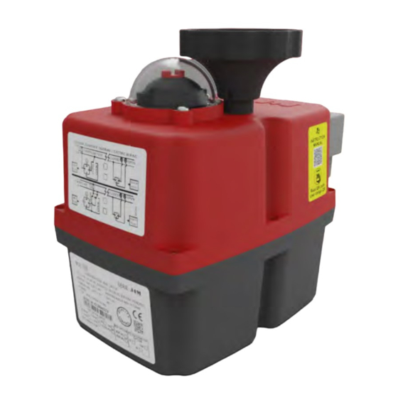
- Page 3 HANDBOOK_ ACTUATOR PART LIST 01 ACTUATOR PART LIST MODELS: S2, S6, S10, B2, B6, B10 Manual override visual control of operation Position indicator Signal plug Power supply plug Volt free contact plug Automatic-manual lever ISO multiflange INDEX...
- Page 4 HANDBOOK_ ACTUATOR PART LIST MODELS: S25, S40, B25, B40 Manual override Position indicator visual control of operation Power supply plug Signal plug Volt free contact plug Automatic-manual lever ISO multiflange INDEX...
- Page 5 VOLTAGE TO BE CONNECTED All our actuators model S2 to S40 are ready to work from 24-240 VDC/VAC. All our actuators model B2 to B40 are ready to work at 12 VDC/VAC ONLY.
- Page 6 _ 04 HANDBOOK_ J4M SERIES ID ACTUATOR LABEL Actuator Model. Bar code of the serial number. 10 - Actuator Series. Voltage to be connected. 11 - Max. Number Turns. Time/Turn. 12 - Duty: 75%. Actuator ready to bear between –20ºC &...
- Page 7 HANDBOOK_ J4M SERIES LOCAL VISUAL POSITION INDICATOR All J4M actuators are supplied with a local visual position indicator (Fig.6). The OPEN position shows the indicator in BLACK and at the end of the stroke (max 14 turns) shows the full indicator in RED. Fig.
- Page 8 HANDBOOK_ J4M SERIES Fig. 7 J4M 2,6 and 10 Fig. 7 J4M 25 and 40 J4M 2, 6 and 10 J4M 25 and 40 Hand Wheel Position Indicator Automatic - Manual When “MAN” function is selected: 1 - The electronic system cuts the power to the motor after a few minutes. 2 - The mechanical connection between the motor and the output shaft is disconnected.
-
Page 9: Table Of Contents
HANDBOOK_ELECTRICAL DIAGRAMS 09 ELECTRICAL DIAGRAMS J4M 3 WIRES ON-OFF J4M 2/10 J4M 25/40 [Capte la J4M 2/10 2 WIRES ON-OFF [Capte la J4M 25/40 [Capte la POSITIONER J4M 2/10 J4M 25/40 INDEX... -
Page 10: J4M 2/10
HANDBOOK_ELECTRICAL DIAGRAMS 10 ELECTRICAL DIAGRAMS J4M POSITIONER ONLY OUTPUT J4M 2/10 A= Power supply plug A: VAC 3 WIRES (Grey plug) PIN1 = NEUTRAL + PIN 2 = Close PIN1 = NEUTRAL + PIN 3 = Open PIN1 = NEUTRAL + PIN2+PIN3 = STOP A: VDC 3 WIRES (Grey plug) PIN1 = NEGATIVE + PIN 2 = POSITIVE = Close J4M 25/40... -
Page 11: J4M
HANDBOOK_ DATASHEET - J4M 2 _ 03 Datasheet - J4M 2 GENERAL CHARACTERISTICS MATERIAL: Body: Anticorrosive Polyamide, Grey colour / Optional: Polypropilene V0, Black colour. Cover: Anticorrosive Polyamide, Red colour / Optional: Polypropilene V0, Natural colour. Output drive: Zamak, Zinc plated / Optional: Zamak, TEFLON coated Flange: ZamaK and Zinc plated / Optional: Zamak and TEFLON coated. - Page 12 HANDBOOK_ DATASHEET - J4M 2 _ J4M 2 SIZES INDEX...
-
Page 13: J4M
HANDBOOK_ DATASHEET - J4M 6 _ Datasheet - J4M 6 GENERAL CHARACTERISTICS MATERIAL: Body: Anticorrosive Polyamide, Grey colour / Optional: Polypropilene V0, Black colour. Cover: Anticorrosive Polyamide, Red colour / Optional: Polypropilene V0, Natural colour. Output drive: Zamak, Zinc plated / Optional: Zamak, TEFLON coated Flange: ZamaK and Zinc plated / Optional: Zamak and TEFLON coated. - Page 14 HANDBOOK_ DATASHEET - J4M 6 _ J4M 6 SIZES INDEX...
-
Page 15: J4M
HANDBOOK_ DATASHEET - J4M 10 _ Datasheet - J4M 10 GENERAL CHARACTERISTICS MATERIAL: Body: Anticorrosive Polyamide, Grey colour / Optional: Polypropilene V0, Black colour. Cover: Anticorrosive Polyamide, Red colour / Optional: Polypropilene V0, Natural colour. Output drive: Zamak, Zinc plated / Optional: Zamak, TEFLON coated Flange: Aluminum and Cataphoresis / Optional: Aluminum and TEFLON coated. - Page 16 HANDBOOK_ DATASHEET - J4M 10 _ J4M 10 SIZES INDEX...
- Page 17 HANDBOOK_ DATASHEET - J4M 25_ Datasheet - J4M 25 GENERAL CHARACTERISTICS MATERIAL: Body: Anticorrosive Polyamide, Grey colour / Optional: Polypropilene V0, Black colour. Cover: Anticorrosive Polyamide, Red colour / Optional: Polypropilene V0, Natural colour. Output drive: Zamak, Zinc plated / Optional: Zamak, TEFLON coated Flange: Aluminum and Cataphoresis / Optional: Aluminum and TEFLON coated.
-
Page 18: J4M
HANDBOOK_ DATASHEET - J4M 25_ J4M 25 SIZES INDEX... - Page 19 HANDBOOK_ DATASHEET - J4M 40_ Datasheet - J4M 40 GENERAL CHARACTERISTICS MATERIAL: Body: Anticorrosive Polyamide, Grey colour / Optional: Polypropilene V0, Black colour. Cover: Anticorrosive Polyamide, Red colour / Optional: Polypropilene V0, Natural colour. Output drive: Zamak, Zinc plated / Optional: Zamak, TEFLON coated Flange: Aluminum and Cataphoresis / Optional: Aluminum and TEFLON coated.
-
Page 20: J4M
HANDBOOK_ DATASHEET - J4M 40_ J4M 40 SIZES INDEX... - Page 21 HANDBOOK_ INTERFACE BLUETOOTH PROGRAM_ INTERFACE BLUETOOTH PROGRAM ACTUATORS INTERFACE USER MANUAL Click on OPEN INTERFACE PROGRAM “BLUETOOTH” Select the MAC or the DEVICE NAME to which you’d like to connect and click on “CONTINUE” green The Bluetooth icon in color, shows that the program is connected to the actuator.
- Page 22 HANDBOOK_ INTERFACE BLUETOOTH PROGRAM_ to configurate the BLUETOOTH parameters. · Click on · Read only parameters: Firmware: Firmware version. MAC: Bluetooth MAC. · Adjustable parameters: To change the Bluetooth and password, follow the steps: 1. Write the new name, on the Bluetooth field. 2.
- Page 23 HANDBOOK_ INTERFACE BLUETOOTH PROGRAM_ After the RESET BLUETOOTH has finished, Click on “BLUETOOTH” click on to the program be reset. Select the MAC or the DEVICE NAME to which you’d like to connect and click on “CONTINUE” INDEX...
- Page 24 HANDBOOK_ INTERFACE BLUETOOTH PROGRAM_ green The Bluetooth icon in color, shows that the program is connected to the actuator. The icon in color means the program has lost connection with the actuator. grey The icon in color means that none actuator has been connected to the program, since it has been opened.
- Page 25 HANDBOOK_ INTERFACE BLUETOOTH PROGRAM_ If you click on COUNTERS option, a screen will appear with all the COUNTERS values. To see the values, click on READ. Short definition of the COUNTERS: Version: Is the software version of the actuator Control PCB. Options: Internal parameter for our engineers to work with.
- Page 26 HANDBOOK_ INTERFACE BLUETOOTH PROGRAM_ REMOTE CONTROL: For On-Off actuators only. You could OPEN/CLOSE/ STOP OR MIDDLE POSITION by clicking on each option. “ACTUAL STATUS” Click on to update the actuator status. MAIN MENU. To go back, click on Click on MULTI TURN CONFIG. The computer will show the following screen.
- Page 27 HANDBOOK_ INTERFACE BLUETOOTH PROGRAM_ Select between value 2 and 5 of the Pre-Close parameter. Pre-Close: With the NEEDLE configuration, the actuator will never close the valve 100%, as this valve is thought to be for regulation function only. In this case, the Pre-Close parameter value, has to be between 2 – 5, which is the % of the way between the open and the close position, deactivated to protect the needle of the valve.
- Page 28 HANDBOOK_ INTERFACE BLUETOOTH PROGRAM_ Click on SELF ADJUSTMENT. Click on CONFIRM ACTUATOR MOUNTED ON THE VALVE. If the actuator is in OPEN position, Open Confirmation button will be in green color. If not, drive the actuator to the OPEN position and the button will become green. Put the declutching lever in AUTO position, and click on CONFIRM ACTUATOR LEVER IN AUTO POSITION.
- Page 29 HANDBOOK_ INTERFACE BLUETOOTH PROGRAM_ Click on CONFIRM SELF-DJUSTMENT. The actuator will make a complete maneuver set-up, loading all the configuration parameters and the OPEN & CLOSE position. Self-adjustment done. To go back, click on MAIN MENU. INDEX...
- Page 30 HANDBOOK_ BLUETOOTH_30 BLUETOOTH communication via BLUETOOTH We have introduced the BLUETOOTH communication system in our actuators, in order to communicate with our actuators, from any IOS or ANDROID devices. From our phone, tablet or PC device we could order our actuator to open/close or stop, we could also be informed about additional data from our actuator.
- Page 31 HANDBOOK_ MODBUS_ MODBUS MODBUS system · Plug and play. · Each device could be operated manually. · Could be seen from the control panel and PC. · Fast and flexible, starting by 1 actuator up to 255. · Up to 1.200m distance range. ·...
- Page 32 HANDBOOK_ GUARANTEE_ 06 GUARANTEE OUR WARRANTY INCLUDES SOLELY AND EXCLUSIVELY THE REPAIR OR REPLACEMENT OF THE DEFECTIVE PARTS IN OUR WORKSHOP OR IN THE PLACEMENT OF THE INSTALLATION, AND DOES NOT COVER INDEMNIFICATIONS OR OTHER EXPENSES. The warranty will be void if the device has been open, if the defects are the result of the misuse or if our products have been handled, repaired or modified outside our workshop or have been installed with materials or by methods not in accordance with our STANDARDS.
- Page 33 HANDBOOK_ CONTACT_ 07 CONTACT J.J. BCN INTERNACIONAL, SA Polígon Industrial Sud Carrer de l'Orfeó Català, 7 • 08440 Cardedeu Barcelona (Spain) (+34) 93 871 33 04 info@jjbcn.com www.jjbcn.com INDEX...
Need help?
Do you have a question about the S2 and is the answer not in the manual?
Questions and answers