Advertisement
Quick Links
Advertisement

Subscribe to Our Youtube Channel
Related Manuals for J+J S20


Summary of Contents for J+J S20
- Page 1 www.jjbcn.com J.J. BCN INTERNACIONAL, S.A. HANDBOOK...
- Page 2 HANDBOOK INDEX 01. Actuator Part List 04. Options · · S20, S35, S55, S85, B20, B35, B55, B85 · S140, S300, B140 · · Bluetooth 02. J4C Series · Modbus · Voltage 05. Kits · Electrical Connectors · · ID Actuator Label ·...
- Page 3 HANDBOOK_ ACTUATOR PART LIST 01 ACTUATOR PART LIST MODELS: S20, S35, S55, S85, B20, B35, B55, B85 Manual override Position indicator visual control of operation Volt free contact plug Power supply plug ISO multiflange Automatic-manual lever INDEX...
- Page 4 HANDBOOK_ ACTUATOR PART LIST MODELS: S140, S300, B140, B300 Manual override Position indicator visual control of operation Volt free contact plug Power supply plug Automatic-manual lever ISO multiflange INDEX...
-
Page 5: Electrical Connectors
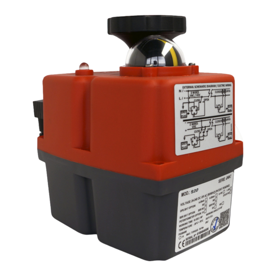
VOLTAGE TO BE CONNECTED All our actuators model S20 to S300 are ready to work from 24-240 VDC/VAC. All our actuators model B20 to B300 are ready to work at 12 VDC/VAC ONLY. - Page 6 Actuator Model. 11 - Working angle. Voltage to be connected. 12 - Duty: 75%. Example: S20 Model - Time the actuator needs to run to the Maneuver time = 10sec. indicated degrees. Time between maneuvers = 3.3 sec. Actuator ready to bear between –20ºC 13 - Actuator with the IP67 protection.
- Page 7 HANDBOOK_ J4C SERIES LOCAL VISUAL POSITION INDICATOR All J4C actuators are supplied with a local visual position indicator comprises a black base with a yellow insert that shows, both the position and direction of rotation (Fig.6). The open and close positions have the following logos molded into the top cover OPEN 90 and CLOSE 0.
- Page 8 HANDBOOK_ J4C SERIES EMERGENCY MANUAL OVERRIDE FACILITY: The J4C has 2 operating modes, automatic and manual, the required mode is selected by using a lever on the lower half of the actuator housing (Fig 7). The 2 positions are marked: AUTO = Automatic operation MAN = Manual operation Warning: Do not remove the selector lever securing screw, as this will allow its internal mechanism...
- Page 9 HANDBOOK_ J4C SERIES When “MAN” function is selected: 1 - The electronic system cuts the power to the motor after a few minutes. 2 - The mechanical connection between the motor and the output shaft is disconnected. 3 - The desired position can be achieved by using the hand wheel. 4 - There are two ways to re-active the motor after being isolated whilst in “MAN”...
- Page 10 HANDBOOK_ J4C SERIES POSITION OF THE CAMS Cams 1 and 3 Cams 2 and 4 Cam 1 is to adjust the close position. Cam 2 is to adjust the open position. Cam 3 is to adjust the close position confirmation. Cam 4 is to adjust the open position confirmation.
- Page 11 HANDBOOK_ J4C SERIES To adjust the close position at less than 0 cams 1 / 3 Turn the wrench to clockwise direction - cams 1 and 3. The cam 3 (confirmation) should press the lever of the micro switch a bit earlier than the cam 1.
- Page 12 HANDBOOK_ J4C SERIES TABLE OF CONSUMPTIONS - ON-OFF ACTUATOR INDEX...
- Page 13 HANDBOOK_ J4C SERIES TABLE OF CONSUMPTIONS - ON-OFF ACTUATOR INDEX...
- Page 14 HANDBOOK_ J4C SERIES TABLE OF CONSUMPTIONS - DPS ACTUATOR INDEX...
- Page 15 HANDBOOK_ J4C SERIES TABLE OF CONSUMPTIONS - DPS ACTUATOR INDEX...
- Page 16 HANDBOOK_ J4C SERIES EXTERNAL CONNECTING DIAGRAM (STANDARD) STANDARD MODE · 3 WIRES ON - OFF 20/85 = Power supply plug VAC 3 WIRES (Grey plug) PIN 1 = Neutral + PIN 2 = Phase = Close PIN 1 = Neutral + PIN 3 = Phase = Open VDC 3 WIRES (Grey plug) PIN 1 = (-) Negative + PIN 2 = (+) Positive = Close PIN 1 = (-) Negative + PIN 3 = (+) Positive = Open...
- Page 17 HANDBOOK_ J4C SERIES EXTERNAL CONNECTING DIAGRAM (OPTIONAL) STANDARD MODE · 3 WIRES ON - OFF 20/85 = Power supply plug VAC 3 WIRES (Grey plug) PIN 1 = Neutral + PIN 2 = Phase = Close PIN 1 = Neutral + PIN 3 = Phase = Open PIN 1 = Neutral + PIN 2+3 = Phase = Stop VDC 3 WIRES (Grey plug) 140/300...
- Page 18 HANDBOOK_ J4C SERIES EXTERNAL CONNECTING DIAGRAM (OPTIONAL) 4 MODE ON - OFF 20/85 = Power supply plug VAC 3 WIRES (Grey plug) PIN 1 = Neutral + PIN 2 = Phase = Stop PIN 1 = Neutral + PIN 3 = Phase = Open PIN 1 = Neutral + PIN 2+3 = Phase = Close VDC 3 WIRES (Grey plug) PIN 1 = (-) Negative + PIN 2 = (+) Positive = Stop...
- Page 19 HANDBOOK_ J4C SERIES ACTUATOR OPERATIONAL STATUS MODELS: 20, 35, 55, 85, 140 & 300 The LED Light provides visual communication between the actuator and the user. The current operational status is shown by different LED colors. ON-OFF ACTUATOR ACTUATOR OPERATIONAL STATUS Without power supply ..................................................
- Page 20 HANDBOOK_ J4C SERIES ACTUATOR WITH BSR ACTUATOR OPERATIONAL STATUS Without power supply ....................................................In open position ......................................................... In close position ......................................................... Opening ............................................................Closing ............................................................Torque limiter function on, moving from close to open ..................................Torque limiter function on, moving from open to close ..................................
-
Page 21: Data Sheet
HANDBOOK_ DATASHEET - J4C 20 _ 03 Datasheet - J4C 20 GENERAL CHARACTERISTICS MATERIAL: Body: Anticorrosive Polyamide, Grey colour / Optional: Polypropilene V0, Black colour. Cover: Anticorrosive Polyamide, Red colour / Optional: Polypropilene V0, Natural colour. Output drive: Zamak, Zinc plated / Optional: Zamak, TEFLON coated Flange: ZamaK and Zinc plated / Optional: Zamak and TEFLON coated. - Page 22 HANDBOOK_ DATASHEET - J4C 20 _ J4C 20 SIZES INDEX...
-
Page 23: Exploded View
HANDBOOK_ DATASHEET - J4C 20_ Exploded View J4C 20 CODE QUANTITY CODE QUANTITY CODE QUANTITY AP00345 AP00042 1(*09) AP01099 AP00372 MM00187 MM01382 AP00346 AP00456 +AP00013 AP00053 AP00056 +AP01042 AP00133 AP00054 +AP00084 AP00457 MM00258 AP00340 * AP01098 AP00541 AP00023 AP00067 AP00455 AP00037 AP00068 AP00050... - Page 24 HANDBOOK_ DATASHEET - J4C 20_ Exploded View J4C 20 CODE QUANTITY CODE QUANTITY AP00057 AP00974 AP00794 AP00032 AP00991 AP00021 AP01013 AP00960 AP01000 AP00143 AP00343 AP00955 AP00031 AP00861 AP00014 AP00145 AP00251 INDEX...
- Page 25 HANDBOOK_ DATASHEET - J4C 20_ Exploded View J4C 20 QUANTITY QUANTITY QUANTITY CODE CODE CODE AP00533 1 (S TYPE) MM01211 AP00911 AP01059 1 (B TYPE) MM01210 AP00879 AP00080 AP01000 AP01056 AP01047 AP00070 AP00926 AP00161 AP01045 AP00048 AP00159 AP01015 AP01066 AP00376 AP01017 MM01324 INDEX...
- Page 26 HANDBOOK_ DATASHEET - J4C 35 _ Datasheet - J4C 35 GENERAL CHARACTERISTICS MATERIAL: Body: Anticorrosive Polyamide, Grey colour / Optional: Polypropilene V0, Black colour. Cover: Anticorrosive Polyamide, Red colour / Optional: Polypropilene V0, Natural colour. Output drive: Zamak, Zinc plated / Optional: Zamak, TEFLON coated Flange: ZamaK and Zinc plated / Optional: Zamak and TEFLON coated.
- Page 27 HANDBOOK_ DATASHEET - J4C 35 _ J4C 35 SIZES INDEX...
- Page 28 HANDBOOK_ DATASHEET - J4C 35_ Exploded View J 4C 35 INDEX...
- Page 29 HANDBOOK_ DATASHEET - J4C 35_ Exploded View INDEX...
- Page 30 HANDBOOK_ DATASHEET - J4C 35_ Exploded View J4C 35 INDEX...
- Page 31 HANDBOOK_ DATASHEET - J4C 55 _ Datasheet - J4C 55 GENERAL CHARACTERISTICS MATERIAL: Body: Anticorrosive Polyamide, Grey colour / Optional: Polypropilene V0, Black colour. Cover: Anticorrosive Polyamide, Red colour / Optional: Polypropilene V0, Natural colour. Output drive: Zamak, Zinc plated / Optional: Zamak, TEFLON coated Flange: Aluminum and Cataphoresis / Optional: Aluminum and TEFLON coated.
- Page 32 HANDBOOK_ DATASHEET - J4C 55 _ J4C 55 SIZES INDEX...
- Page 33 HANDBOOK_ DATASHEET - J4C 55_ Exploded View INDEX...
- Page 34 HANDBOOK_ DATASHEET - J4C 55_ Exploded View J4C 55 INDEX...
- Page 35 HANDBOOK_ DATASHEET - J4C 55_ Exploded View J4C55 INDEX...
- Page 36 HANDBOOK_ DATASHEET - J4C 85_ Datasheet - J4C 85 GENERAL CHARACTERISTICS MATERIAL: Body: Anticorrosive Polyamide, Grey colour / Optional: Polypropilene V0, Black colour. Cover: Anticorrosive Polyamide, Red colour / Optional: Polypropilene V0, Natural colour. Output drive: Zamak, Zinc plated / Optional: Zamak, TEFLON coated Flange: Aluminum and Cataphoresis / Optional: Aluminum and TEFLON coated.
- Page 37 HANDBOOK_ DATASHEET - J4C 85_ J4C 85 SIZES INDEX...
- Page 38 HANDBOOK_ DATASHEET - J4C 85_ Exploded View INDEX...
- Page 39 HANDBOOK_ DATASHEET - J4C 85_ Exploded View INDEX...
- Page 40 HANDBOOK_ DATASHEET - J4C 85_ Exploded View INDEX...
-
Page 41: Data Sheet
HANDBOOK_ DATASHEET - J4C 140_ Datasheet - J4C 140 GENERAL CHARACTERISTICS MATERIAL: Body: Anticorrosive Polyamide, Grey colour / Optional: Polypropilene V0, Black colour. Cover: Anticorrosive Polyamide, Red colour / Optional: Polypropilene V0, Natural colour. Output drive: Zamak, Zinc plated / Optional: Zamak, TEFLON coated Flange: Aluminum and Cataphoresis / Optional: Aluminum and TEFLON coated. - Page 42 HANDBOOK_ DATASHEET - J4C 140_ J4C 140 SIZES INDEX...
- Page 43 HANDBOOK_ DATASHEET - J4C 140_ Exploded View INDEX...
- Page 44 HANDBOOK_ DATASHEET - J4C 140_ Exploded View INDEX...
- Page 45 HANDBOOK_ DATASHEET - J4C 140_ Exploded View J4C 140 INDEX...
- Page 46 HANDBOOK_ DATASHEET - J4C 300_ Datasheet - J4C 300 GENERAL CHARACTERISTICS MATERIAL: Body: Anticorrosive Polyamide, Grey colour / Optional: Polypropilene V0, Black colour. Cover: Anticorrosive Polyamide, Red colour / Optional: Polypropilene V0, Natural colour. Output drive: Zamak, Zinc plated / Optional: Zamak, TEFLON coated Flange: Aluminum and Cataphoresis / Optional: Aluminum and TEFLON coated.
- Page 47 HANDBOOK_ DATASHEET - J4C 300_ J4C 300 SIZES INDEX...
- Page 48 HANDBOOK_ DATASHEET - J4C 300_ Exploded View J4C 300 INDEX...
- Page 49 HANDBOOK_ DATASHEET - J4C 300_ Exploded View INDEX...
- Page 50 HANDBOOK_ DATASHEET - J4C 300_ Exploded View J4C 300 INDEX...
-
Page 51: Specifications
HANDBOOK_ Optios DPS_ 04 Electric actuators with POSITIONER DPS J4C 20/85 SPECIFICATIONS S20-B20 S35-B35 S55-B55 S85-B85 F.S. Full scale INDEX... - Page 52 HANDBOOK_ Optios DPS_ DPS J4C 20/85 Use the configuration you need by moving the DIPs: Different possibilities of configuration: Configurations set up by using DIPs, should have the same Input and Output Signal. I.e.: If Set up Input signal 4/20mA-Output signal 4/20 mA. Other possibilities are available to work with, but they should be configurated from the manufacturer.
- Page 53 HANDBOOK_ Optios DPS_ DPS EXTERNAL SELF-ADJUSTMENT A- Power supply plug. B- Volt free contact plug. C- Input / Output signal (4/20mA,0/10V,0/20mA o 1/10V) plug. 1-C plug - connect a cable between PIN 1 (on the left side) and PIN Earth (on the bottom). 2-A plug - connect: VAC: PIN1 (neutral) and PIN2 (phase).
- Page 54 HANDBOOK_ Optios DPS_ DPS J4C 140/300 SPECIFICATIONS S140-B140 S300-B300 F.S. Full scale INDEX...
- Page 55 HANDBOOK_ Optios DPS_ DPS J4C 140/300 Use the configuration you need by moving the DIPs: Different possibilities of configuration: Configurations set up by using DIPs, should have the same Input and Output Signal. I.e.: If Set up Input signal 4/20mA-Output signal 4/20 mA. Other possibilities are avalilable to work with, but they should be configurated from the manufacturer.
- Page 56 HANDBOOK_ Optios DPS_ DPS EXTERNAL SELF-ADJUSTMENT A- Power supply plug. B- Volt free contact plug. C- Input / Output signal (4/20mA,0/10V,0/20mA o 1/10V) plug. 1-C plug - connect a cable between PIN 1 (on the left side) and PIN Earth (on the bottom). 2-A plug - connect: VAC: PIN1 (neutral) and PIN2 (phase).
- Page 57 HANDBOOK_ Optios BSR_ OPTIONS BSR BSR J4C 20/85 SPECIFICATIONS S20-B20 S35-B35 S55-B55 S85-B85 Until battery Until battery Until battery Until battery discharged discharged discharged discharged 2,000 Kg 2,000 Kg 2,500 Kg 3,000 Kg INDEX...
- Page 58 HANDBOOK_ Optios BSR_ Jumper 1 SELDIR NC Set-Up NC - If, in case of a power supply failure, we need the actuator go to the CLOSE position, we need to put the jumper 1 on the SELDIR position. NO Set-Up NO - If, in case of a power supply fail- ure, we need the actuator go to the OPEN position, be sure that...
- Page 59 HANDBOOK_ Optios BSR_ BSR J4C 140/300 SPECIFICATIONS S300-B300 S140-B140 INDEX...
- Page 60 HANDBOOK_ Optios BSR_ SELDIR jumper (*) NO or NC Set-Up NC Set-Up NC - If, in case of a power supply failure, we need the actuator go to the CLOSE position, we need to put the jumper 1 on the SELDIR position.
- Page 61 (see characteristics). The DPS in communication with the electronic OUTSIDE BOX INSIDE BOX system of the actuator provides an integral mana- gement of the motion of the actuator. SPECIFICATIONS S20-B20 S35-B35 S55-B55 S85-B85 F.S. Full scale INDEX...
- Page 62 HANDBOOK_ KIT DPS_ ASSEMBLY INSTRUCTIONS - DPS KIT 20/85 KIT COMPONENTS Element - 1 Cover Element - 1 Plastic column Element - 1 DPS positioner PCB Element - 2 Sheet metal Fixing screws Element - 1 Plastic Fixing screws * Fill in the document inside the kit, and send it to the fax number or e-mail, shown in the document The unit is ready to work.
- Page 63 HANDBOOK_ KIT DPS_ Carefully remove the position indicator. Remove the cables (from the cover) connected to the Fix the plastic column (Element B) on the base plate, by using Remove the screw, which is fixing Remove the 6 screws, which are fixing Carefully lift the cover.
- Page 64 HANDBOOK_ KIT DPS_ KIT DPS J4C 140/300 The DPS is a device for the J4C electric actuator that turns the actuator into a servo controlled valve positioner. The DPS is a modulus with a microprocessor (CPU) which digitally manages the analogical input and output and compare them with the position of the actuator to establish a uniform relation.
- Page 65 HANDBOOK_ KIT DPS_ ASSEMBLY INSTRUCTIONS - DPS KIT 140/300 KIT COMPONENTS Element - 1 Cover Element - 1 Plastic column Element - 1 DPS positioner PCB Element - 2 Sheet metal Fixing screws Element - 1 Plastic Fixing screws Element - 1 Schematic diagram label * Fill in the document inside the kit, and send it to the fax number (93 871 32 72) or e-mail: info@jjbcn.com, shown in the document.
- Page 66 HANDBOOK_ KIT DPS_ Remove the screw, which is fixing Remove the 8 screws, which are fixing Remove the cables (from the cover) connected to the actuator PCB (Fig. A, B and C). Carefully lift the cover. Carefully remove the position indicator. the hand wheel.
- Page 67 BSR system returns the valve back to the preferable position by means of the batteries tension, operating as a “single acting” actuator. OUTSIDE BOX INSIDE BOX S20-B20 S35-B35 S55-B55 S85-B85 INDEX...
- Page 68 HANDBOOK_ KIT BSR_ ASSEMBLY INSTRUCTIONS · BSR KIT 20/85 VERY IMPORTANT: PLEASE, FOLLOW THESE INSTRUCTIONS STEP BY STEP. IF THE CONNECTOR OF THE BATTERY PACK IS PLUGGED INTO THE "BSR" PCB, BEFORE ARRIVING TO POINT 7, THE PCB COULD BE DAMAGED. KIT COMPONENTS Element A - 1 BSR PCB.
- Page 69 HANDBOOK_ KIT BSR_ Fix it to the actuator metal plate, by using the Sheet metal fixing screw ( Element E). Remove the screw, which is fixing the Remove the 6 screws between the Take the BSR PCB (Element A) from the KIT and connect it to the Carefully lift the cover.
- Page 70 HANDBOOK_ KIT BSR_ KIT BSR J4C 140/300 The BSR safety block system is an automatism that, when coupled to the J4C multi voltage electric actuators, lets the valve situate in a preferable position NC or NO, when there is a power supply failure.
- Page 71 HANDBOOK_ KIT BSR_ ASSEMBLY INSTRUCTIONS · BSR KIT 140/300 VERY IMPORTANT: PLEASE, FOLLOW THESE INSTRUCTIONS STEP BY STEP.IF THE CONNECTOR OF THE BATTERY PACK IS PLUGED TO THE “BSR” PCB, BEFORE ARRIVING TO POINT 4, THE PCB COULD BE DAMAGED. Connect 1 Connect 2 KIT COMPONENTS...
- Page 72 HANDBOOK_ KIT BSR_ Fix it to the actuator metal plate, by using the Sheet metal Remove the hand wheel screw and Take the BSR PCB (Element B) from the KIT and connect it to Remove the 8 screws between the Carefully remove the cover, in order to fixing screw (Element D).
- Page 73 HANDBOOK_ KIT INTERFACE_ KIT INTERFACE By using the INTERFACE KIT cable we stablish communication with the actuator, read parameters and change the set-up values. INTERFACE PROGRAM for PC INSTALLATION: Download the Interface program from: https://www.dropbox.com/sh/4qgczg8zspwtehc/AABD0TkZouJ2-DXxidzk8Jera?dl=0 1 · Download the file 2 ·...
- Page 74 HANDBOOK_ KIT INTERFACE_ 5.3 Click on “Next” 5.4 Click on “Next” 5.5 Click on “Next” 5.6 Cick on “Restart” 6 · The Program set-up is finished 7 · Go to “Inicio”, “Todas la aplicaciones” and in file 8 · Open INDEX...
- Page 75 HANDBOOK_ KIT INTERFACE_ CONNECT THE INTERFACE CABLE TO THE J4C ELECTRIC ACTUATOR KIT INTERFACE J4C 1 · Use the INTERFACE cable inside the KIT box. 2 · Before connecting it to a J4C actuator, remove the cover of the actuator and connect one of the Interface cable sides as per our (image 1).
- Page 76 HANDBOOK_ KIT INTERFACE_ INTERFACE PROGRAM - HOW IT WORKS? INTERFACE PROGRAM FOR J4 Y J4C SERIES ACTUATORS ONLY. 1 · Open the program see the following screen Two RED buttons appear on the screen. Button 1 shows the USB Interface connector is not connected to the PC.
- Page 77 The Banda Prop parameter should be 32 in all our standard models. Only in case of a S20 or B20 model with a 5 Sec./90º working time, the Banda Prop value should change into 55. Otherwise, the positioner (DPS) could not work in a proper way.
- Page 78 HANDBOOK_ KIT INTERFACE_ This configuration is possible only if our Positioner (DPS) has already been installed in the actuator. Click on DPS, if the following screen appears, please place the DIPs on the DPS PCB, following the screen instructions. Click on MAIN MENU. If we click on DPS, all the Positioner (DPS) possible configuration options will be shown on the following screen:...
- Page 79 HANDBOOK_ KIT INTERFACE_ REMOTE CONTROL options: In case of an ON-OFF or a DPS Output only actuator, Click on ABRIR, CERRAR and PARAR options to activate it. Only in case of having a 3-position actuator, the screen will show an additional option PUNTO MEDIO, which stops the actuator at an intermediate position.
-
Page 80: Bluetooth & Wifi
HANDBOOK_ BLUETOOTH & WIFI_80 BLUETOOTH & WIFI communication BLUETOOTH We have introduced the BLUETOOTH communication system in our actuators, in order to communicate with our actuators, from any IOS or ANDROID devices. this system appears in our catalogue as a factory option. From our mobile phone or tablet we could order our actuator to open/close or stop, we could be informed about errors or incidences, etc. - Page 81 HANDBOOK_ MODBUS_ MODBUS system · Plug and play. · Each device could be operated manually. · Could be seen from the control panel, tablet, mobile, PC, either inside or outside of the plant. · Fast and flexible, starting by 3 actuators up to 32 ·...
- Page 82 HANDBOOK_ CERTIFICATIONS_ 06 CERTIFICATIONS · IP 67 · Reach Certificate of Compliance · Rohs Certificate of Compliance · CE Certificates · ISO 9001:2015 INDEX...
- Page 89 ISO 9001 REGISTERED This document certifies that the quality management systems of: J.J. BCN INTERNACIONAL, S.A. C/ De l’Orfeó Català, 7 (P.I. Sud) – 08440, CARDEDEU (Barcelona) have been assessed and approved by QMS Spain to the following Quality management systems, standards and guidelines: ISO 9001:2015 The approved quality management systems apply to the following: MANUFACTURING, MARKETING AND TECHNICAL ASSISTANCE OF VALVE...
- Page 90 GUARANTEE_ 07 GUARANTEE J+J actuators are warranted against defects of workmanship or assembly as follows: J4C S/B Series: up to 60.000 working cycles or 3 years from their shipment date. Working conditions of a 75% of duty. Max number of 50 limiter function activations, within 3 years of the warranty period.
- Page 91 HANDBOOK_ CONTACT_ 08 CONTACT J.J. BCN INTERNACIONAL, SA Polígon Industrial Sud Carrer de l'Orfeó Català, 7 • 08440 Cardedeu Barcelona (Spain) (+34) 93 871 33 04 info@jjbcn.com www.jjbcn.com INDEX...
Need help?
Do you have a question about the S20 and is the answer not in the manual?
Questions and answers