
Related Manuals for J+J J2 L/H 10


Summary of Contents for J+J J2 L/H 10
- Page 1 Manual J+J Quarter Turn Actuators T e l . : + 4 9 5 1 8 1 6 0 1 7 | i n f o @ j u j - d e u t s c h l a n d . d e | w w w . j u j - d e u t s c h l a n d . d e...
- Page 2 For this documentation the claims author's legal protection. This documentation may not be extended without previous written agreement of the company J+J Deutschland GmbH, neither amended, multiplied nor transmitted for use to third party. To the demand of these documents, please, address J+J Deutschland GmbH.
-
Page 3: Table Of Contents
Index Introduction ..............4 General advise. -
Page 4: Introduction
Introduction Dear customer, dear assembler and user these mounting and operating manual apply to all J+J Electrical Part Turn Actuators of the series J2, J3, J3C. It should provide information and knowledge for you to execute the assembly and instalation. Pay attention particularly to the security indications. -
Page 5: General Advise
G e n e r a l a d v i c e The transport to the installation location should always take place in a fixed packaging. Do not carry the actuator on the hand wheel and do not attach any hoists to the hand wheel. Entry control Check directly after delivery the actuator for possible damages in transit and faults. -
Page 6: Safety Notes
Safety notes Does the actuator the required version ( torque, protection, voltage, swivel angle, etc.). Does the wiring acc. to the voltage (see diagram/type label). Is it possible to adjust the valve on the manual override. Switch from AUTO to MAN, move the handwheel/ handlever to synchronize the transmission then exit the adjustment path manually and turn back to the starting position. - Page 7 S a f e t y n o t e s Settings and Commissioning Make sure that the starting or the test settings on the actuator, no potential hazards to personnel or the environment. If necessary, set up warning signs, so that unintentional operation is prevented. ...
-
Page 8: Device Description
D e v i c e D e s c r i p t i o n Application Integrated Systems: ETL (electronic torque limiter) AVS (auto voltage sensing) ATC (automatic temperature control) PEC (protected electrical connection) Function A DC-motor actuate the main shaft via a gearbox. -
Page 9: Model Overview
D e v i c e D e s c r i p t i o n Model Overview J2 L/H 10 J3 S20 20 Nm Torque 10 Nm Torque 25 Nm Break torque 12 Nm Break torque 24 - 240 V AC/DC... -
Page 10: Part Description
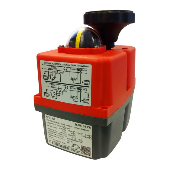
D e v i c e D e s c r i p t i o n ower Connector onnector for the Additional Limit Switches witch from Automatic to Manual (AUTO/MAN) and Wheel and Lever/Indicator ptical Position Indicator/Dome - Status LED (not for model 10 ) E.L.S. -
Page 11: Type Label J2/ J3
D e v i c e D e s c r i p t i o n Type label J2/ J3 By means of the nameplate identifies each actuator. Note: The label should not be damaged or removed. 1. Model pecifying the model. - Page 12 D e v i c e D e s c r i p t i o n Type label J3C S By means of the nameplate identifies each actuator. Note: The label should not be damaged or removed. 10/11 12/13 1.
-
Page 13: Status Led
D e v i c e d e s c r i p t i o n Status-LED J3/ J3C The operating status of the actuator is displayed by the signal light in the lid. The flashing frequency is shown in the table below as a binary number (in the "Indicator"... -
Page 14: Emergency Manual Override
D e v i c e d e s c r i p t i o n Automatic mode = AUTO • Manual operation mode = MAN • Position switch MAN Manual Operation - MAN Position switch to AUTO Automatic Operation - AUTO There are two ways of switching from "MAN"... -
Page 15: Installation
Installation The actuator must be protected against outdoor heating by solar radiation, freezing, UV radiation (e.g. shelter / roof).To avoid condensation, the control room heater must be active, i.e. the supply voltage must be applied continuously. Cabling and connector seals should be checked for proper fit and tightness. In cold or hot liquids above or below the temperature range (-20°C to 70°C), a temperature derivative should be provided. -
Page 16: Mounting Of The Valve
Installation Mounting of the valve Insertion depth Insertion depth of the actuator wave socket The insertion depth of the valve´s square socket to be assembled to the actuator´s double square socket should be always less than or equal to the insertion depth of actuator. - Page 17 Installation Flange Stecker Gehäuse Screw 5,1 Nm 8,8 Nm 21,5 Nm 44 Nm 65 Nm 0,5 Nm 2,6 Nm Mounting torque Required mounting material: Material for the direct actuator design With screws: Alternatively with headless screws - 4 screws headless screws - 4 washers - 4 washers - 4 nuts...
-
Page 18: Alternation Multi Flange Plate In Model 10 And 20
Installation Alternation multi flange plate in types 10 to 35 To use all flanges sizes according to ISO 5211 is structurally necessary (for model 10 and 35) to rotate the multi flange plate. Thus the position indicator of the actuator matches with the function of the valve (on / off), the multi flange plate must be rebuilt with model 10 and 20, if necessary. -
Page 19: Conversion Double Square Adapter
Installation Conversion double square adapter Appropriate double squares adapter available from your J+J specialist dealer. Model 20/35 Double Square Adapter Possible double square - 9 mm/ 11 mm/14 mm Possible two flat - 11 x 16 mm Working steps are as follow:... -
Page 20: Electrical Installation
E l e c t r i c a l I n s t a l l a t i o n Electrical Installation Standard actuators are single phase to connect. An external fuse must be provided. Do not connect consumers in parallel to the actuator. Connectors Model 10 - 85 Model 140/300... - Page 21 Electrical Installation Mechanical connection of power supply and control line • loosen the fixing screw of the plug and pull it from the actuator terminal • open the plug by pulling the clamp from the housing • lead the cable through to the cable gland on the connector housing •...
-
Page 22: Position Adjustment
P o s i t i o n A d j u s t m e n t Safety All work in the actuator must be carried out only by qualified personnel and disconnected power source. Touching live components can have a dangerous electrical shock and damage the electronics! Purpose The actuators are pre-adjusted. - Page 23 P o s i t i o n A d j u s t m e n t General Switch actuator from automatic to manual mode and approach to changing position of the manual Turn the cam always from the direction in which the main shaft will rotate to the position of the switch override.
- Page 24 P o s i t i o n A d j u s t m e n t Setting instruction of limit switches Model 10 + J3 20 The configuration takes places with a 2 mm allen wrench or a small screwdriver, wich have to stick into the gap of the cam and twist it until a clicking sound of the switch is heard.
- Page 25 P o s i t i o n A d j u s t m e n t Setting instruction of limit switches J3C Series Tool: One special plastic wrench. The wrench was supplied with the actuator and mounted inside the housing .To move the cams, introduce the special plastic wrench in the hole of the cam and turn it round (see both options on the enclosed pictures).
-
Page 26: Jumper Configuration
Jumper Configuration Basic configuration Heater active Optional Configuration Heater inactive - 26 -... -
Page 27: Faq`s
FA Q If you have difficulties, please consult this list first. If you find no solution to the problem in this information, please contact your dealer. Nothing happens, the actuator does not move. Power light does not function. Check the wiring. Is the plug connected? Is there power at the plug? Is the actuator suitable for the applied voltage? - Check type label... -
Page 28: Special Models
Special Models Series J3/J3C... -
Page 29: Actuators With Bsr - Battery Spring Return
A c t u a t o r s w i t h B a t t e r y S p r i n g R e t u r n This instruction is additional to your „ Basic instruction J3 S+ J3C S “. For further technical details and advices please mind those. - Page 30 A c t u a t o r s w i t h B a t t e r y S p r i n g R e t u r n Functional check There is no servicing required! Regular functional checks, must be scheduled, considering to the secruity requirement.
-
Page 31: Actuators With Dps Positioner
A c t u a t o r s w i t h D P S P o s i t i o n e r This instruction is additional to your „ Basic instruction J3 S+ J3C S “. For further technical details and advices please mind those. -
Page 32: Adjust Working Angel
A c t u a t o r s w i t h D P S P o s i t i o n e r Note: At actuators with DPS and BSR you have to unplug the BSR Accupack from the circuit board before you start the adjustment drive! Electrical alignment switch off power supply and open the cover... -
Page 33: Functions Of Status Leds
A c t u a t o r s w i t h D P S P o s i t i o n e r Functions of status LEDs External status indicator LED status time indicator LED colour reached position 100% 1111 1111 1111 1111 blue... -
Page 34: Faq`s
A c t u a t o r s w i t h D P S P o s i t i o n e r Wiring diagram DPS AC/DC Error analysis (FAQ) The actuator positions are not acc. to the input signal reason: drive over the adjusted angel by hand help: see chapter “adjust the DPS positioner systems “... -
Page 35: Actuators With Potentiometer
A c t u a t o r s w i t h P o t e n t i o m e t e r The potentiometer output signal shows the actual position of the valve shafts. The signal is shown in an ohmic value. -
Page 36: Positions Actuators
/ min. end positions(0° / 180°) . All other features (heating, torque protection circuit ...) of J3/J3C standard actuator are retained in this model. Example: J+J Standard 0° - 90° - 180° Wiring Diagram for J3/J3C Modelle 0° - 90° - 180°... -
Page 37: Actuators With 2 Phases Control
A c t u a t o r s w i t h 2 c o n t r o l p h a s e s This option is not available for J2 10 This option can be ordered with continuous phase NO or NC. This on/off actuator travels in the ordered phase direction (NO or NC). -
Page 38: Appendix
A p p e n d i x... -
Page 39: Technical Data
S p e c i f i c a t i o n s - 39 -... -
Page 40: Current Consumption
S p e c i f i c a t i o n s Current consumption Current consumption and performance for max. torque +/-5% J3C S20/ J3C S35 J3C S55 J3C S85 J3 S20 1200 mA 1600 mA 1730 mA 1170 mA 24 V AC 27,6 W... - Page 41 W i r i n g D i a g r a m s position of plugs Model H/L 10 Models H/L 20, 35, 55, 85 POWER POS. E.L.S. Models H/L 140, 300 - 41 -...
-
Page 42: Wiring Diagrams
W i r i n g D i a g r a m s J2 / J3 / J3C Standard + BSR Potentialfreie Endlagen / potentialfree Ausgang/Output Eingang/Input AC/DC Zu/Close Auf/Open Zu/Close Auf/Open extern 3 Draht/ 2 Punkt external Regelung 2 point control Stecker/Plug 1 Stecker/Plug 4... - Page 43 W i r i n g D i a g r a m s J3/ J3C with Potentiometer Zusätzliche Endschalter/ Auxiliary limit switches Extern/external Ansteuerung: PIN 1 = N/- PIN 2 = L/+ Close/Zu PIN 3 = L/+ Open/Auf PIN 2+3 = Stop J3/ J3C with DPS StandardAC/DC Steuersignal/Control signal...
- Page 44 W i r i n g D i a g r a m s - 44 -...
- Page 45 W i r i n g D i a g r a m s J3/ J3C 2 Phasen control NC Schaltplan für 2 Phasen Ansteuerung: Dauerphase NC Wiring diagram for 2 phases: mainphase NC Zusätzliche Endschalter/Auxiliary limit switches extern/external Eingang/Input Ausgang/Output VAC/VDC Zu/Close...
-
Page 46: Dimensional Drawings
D i m e n s i o n a l D r a w i n g H/L 10 - 46 -... - Page 47 D i m e n s i o n a l D r a w i n g - 47 -...
- Page 48 D i m e n s i o n a l D r a w i n g S20/35 - 48 -...
- Page 49 D i m e n s i o n a l D r a w i n g - 49 -...
- Page 50 D i m e n s i o n a l D r a w i n g - 50 -...
- Page 51 D i m e n s i o n a l D r a w i n g H/L 140/300 - 51 -...
- Page 52 T e l . : + 4 9 5 1 8 1 6 0 1 7 | i n f o @ j u j - d e u t s c h l a n d . d e | w w w . j u j - d e u t s c h l a n d . d e...
- Page 53 Additional instruction for J+J actuators J3 S + J3C S –Series with Positionier (DPS) This instruction is additional to your „ Basic instruction J3 S+ J3C S “. For further technical details and advices please mind those. General: The DPS electronic positioner converts the actuators into servo-controlled control device for valves. Using the input signal of the DPS, it is possible to adjust to any pivoting range of the actuator.
- Page 54 Electrical alignment For the adjustment drive you have to wire and switch on the power supply at plug 1. Note: At actuators with DPS and BSR you have to unplug the BSR Accupack from the circuit board before you start the adjustment drive! switch off power supply and open the cover fig.
- Page 55 Functions of status LEDs External status indicator LED status time indicator LED colour reached position 100% 1111 1111 1111 1111 blue power supply on / actuator moving to „open “ 100% 1111 1111 1111 1111 blue / green (flashing) power supply on / actuator moving to “closed “ 100% 1111 1111 1111 1111 blue / red (flashing)
- Page 56 Wiring diagram DPS AC/DC: Abb. 4 Error analysis (FAQ) The actuator positions are not acc. to the input signal reason: drive over the adjusted angel by hand help: see chapter “adjust the DPS positioner systems “ The actuator drives in the wrong direction at positioner signal (e.g. 0 V = valve is opened) reason: valve is wrong mounted or the rotating direction is changed help: see chapter “adjust the DPS positioner systems “...
Need help?
Do you have a question about the J2 L/H 10 and is the answer not in the manual?
Questions and answers