Table of Contents
Advertisement
Quick Links
Advertisement
Table of Contents

Related Manuals for R&S ZVAX-TRM


Summary of Contents for R&S ZVAX-TRM
- Page 1 ® R&S ZVAX-TRM Extension Unit User Manual (=I<Ò2) 1325.1268.02 ─ 04...
- Page 2 This manual describes the following four extension unit models and their options: ● R&S ® ZVAX-TRM24, order no. 1322.6500.24 ● ® R&S ZVAX-TRM40, order no. 1322.6500.40 ● ® R&S ZVAX-TRM50, order no. 1322.6500.50 ● R&S ® ZVAX-TRM67, order no. 1322.6500.67 Available options include pulse modulators, output amplifiers, and combiners.
-
Page 3: Table Of Contents
® Contents R&S ZVAX-TRM Contents 1 About the Extension Unit..............5 Features......................... 5 Documentation Overview..................... 7 2 Building Blocks and RF Signal Flow............9 Pulse modulators......................10 Output Amplifiers......................10 Broadband Combiners....................10 Direct Generator/Receiver Access................11 RF Signal Flow (w/o combiners)................11 3 Preparing the Extension Unit for Use.......... - Page 4 ® Contents R&S ZVAX-TRM 3.4.9 Standby and Ready State..................... 24 Maintenance........................ 24 Storing and Packing....................25 4 Models and Options................27 Models..........................27 Options.........................27 4.2.1 Overview........................28 4.2.2 Pulse Modulators......................29 4.2.3 Output Amplifiers......................29 4.2.4 Broadband Combiners....................29 4.2.5 Low-noise Preamplifiers....................30 Index......................31...
-
Page 5: About The Extension Unit
1 About the Extension Unit 1.1 Features The R&S ZVAX-TRM is a configurable extension unit for the R&S ZVA and R&S ZVT families of vector network analyzers, enabling enhanced measurements with high sig- nal power, pulsed stimuli, two-tone stimuli or a combination thereof. The focus is on performing measurements on active devices such as T/R modules, receivers or power amplifiers without the need to reconnect the DUT ("single connection measurement"). - Page 6 The extension unit is fully controlled by the analyzer firmware (V3.30 or higher); the management connection is established via USB. Internal components and external user paths of the R&S ZVAX-TRM can be selectively enabled/disabled from the firm- ware on a per-channel basis. Also, the adequate a-wave access can be selected per channel and port.
-
Page 7: Documentation Overview
About the Extension Unit R&S ZVAX-TRM Documentation Overview 1.2 Documentation Overview The functionality of the R&S ZVAX-TRM extension unit is explained in Chapter 2, "Building Blocks and RF Signal Flow", on page 9. For an overview of the front and rear panel controls and connectors of the extension unit see sections Chapter 3.2, "Front Panel... - Page 8 ® About the Extension Unit R&S ZVAX-TRM Documentation Overview User Manual 1325.1268.02 ─ 04...
-
Page 9: Building Blocks And Rf Signal Flow
Building Blocks and RF Signal Flow R&S ZVAX-TRM 2 Building Blocks and RF Signal Flow The block diagram below shows a R&S ZVAX-TRM equipped with all available options (see Chapter 4.2, "Options", on page 27); unavailable modules would be replaced by direct lines. -
Page 10: Pulse Modulators
Source paths 1 and 3 (source paths 2 and 4) can be combined and output to port 1 (port 2) on the R&S ZVAX-TRM. With CW source signals the resulting two-tone output signal is suitable for intermodulation measurements. If both combiners are equipped, a... -
Page 11: Direct Generator/Receiver Access
29. 2.4 Direct Generator/Receiver Access In order to enable application-specific extensions, the R&S ZVAX-TRM frontend pro- vides access to the source and measurement paths of ports 1 and 2, similar to the "Direct Access" connectors at the R&S ZVA/ZVT. This allows to loop external compo- nents (filters, attenuators, isolators, amplifiers etc.) into the related source and/or mea-... - Page 12 ® Building Blocks and RF Signal Flow R&S ZVAX-TRM RF Signal Flow (w/o combiners) R&S ZVA/ZVT R&S ZVAX-TRM Pulse Mod. / Amp. (optional) user- SOURCE defined CW ref. ahead of pulse mod. Port Coupler REF Receiver user- MEAS defined Preamp.
-
Page 13: Preparing The Extension Unit For Use
Storing and Packing....................25 3.1 Safety Instructions The extension unit R&S ZVAX-TRM has been designed and tested in accordance with the EC Certificate of Conformity and has left the manufacturer’s plant in a condition fully complying with safety standards. General safety instructions To maintain this condition and to ensure safe operation, you must observe all instruc- tions and warnings given in this manual. -
Page 14: Front Panel Tour
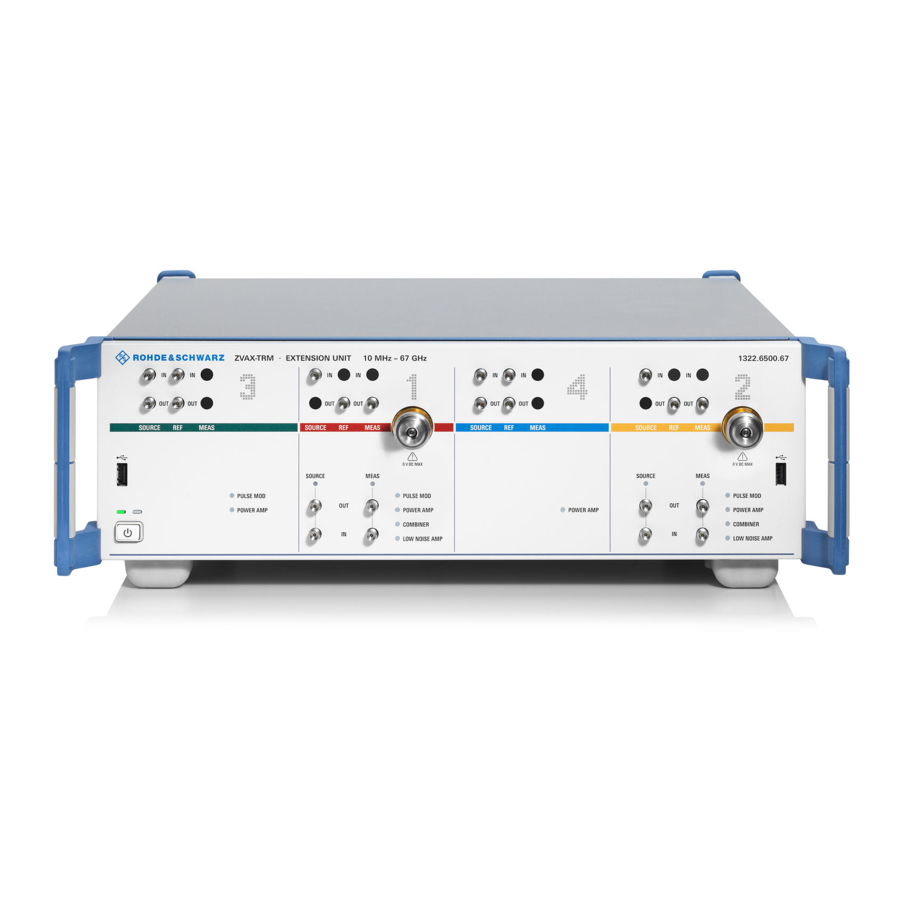
The front panel of the extension unit provides the standby key, two USB connectors (type A), RF connectors for ports 1, 2, 3, and 4, as well as several indicator LEDs. Figure 3-1: R&S ZVAX-TRM Front Panel 3.2.1 Standby Key The standby key connects/disconnects all internal modules of the extension unit to/ from the DC supply voltages generated by its internal power supply. -
Page 15: Usb Connectors
AC power switch if it is not used for some time. 3.2.2 USB Connectors The R&S ZVAX-TRM provides two USB type A connectors on the front panel and another one on the rear panel. Once the extension unit is connected to the network analyzer via the type B USB con- nector on the rear panel of the extension unit (see Chapter 3.3.2, "USB FROM... -
Page 16: Front Panel Indicator Leds
The rear panel contains the mains connector with the AC power switch and several connectors for control and pulse generator signals. Figure 3-2: R&S ZVAX-TRM Rear Panel 3.3.1 Mains Connector and Switch The mains connector is located in the lefthand part of the rear panel; see also Chap- ter 3.4.8, "Power on and... -
Page 17: Usb
® Preparing the Extension Unit for Use R&S ZVAX-TRM Rear Panel Tour With an established connection to USB FROM NWA, the type A USB connectors of the extension unit are functionally equivalent to those of the NWA (USB hub functionality). -
Page 18: Putting The Extension Unit Into Operation
® Preparing the Extension Unit for Use R&S ZVAX-TRM Putting the Extension Unit into Operation 3.4 Putting the Extension Unit into Operation This section describes the basic steps to be taken when setting up the extension unit for the first time. -
Page 19: Instrument Setup
If the extension unit is operated on a bench top, the surface should be flat. Stacked Mounting The R&S ZVAX-TRM is intended to be mounted underneath a R&S ZVA/ZVT. For this reason the extension unit is delivered with adapters for mechanical fixation, including longer screws (with washers). - Page 20 R&S ZVAX-TRM Putting the Extension Unit into Operation Figure 3-3: R&S ZVA67 stacked on top of R&S ZVAX-TRM, units not yet fixed by adapters and screws 1 = front handles 2 = positions for fixing screws User Manual 1325.1268.02 ─ 04...
-
Page 21: Mounting The Extension Unit In A 19'' Rack
Putting the Extension Unit into Operation The following steps must be performed in order to mount the stacked units: 1. Place the R&S ZVA/ZVT on top of the R&S ZVAX-TRM; roughly align the front handles. 2. Remove the original fixing screws at positions 2 in Figure 3-3. -
Page 22: Connecting The Extension Unit To The R&S Zva/Zvt
After positioning (and mechanical fixation) of NWA and extension unit, the units have to be interconnected. 1. USB Connection Use the "USB type A to USB type B" cable delivered with the R&S ZVAX-TRM to connect a USB type A port of the NWA to the USB FROM NWA... -
Page 23: Emi Protective Measures
Connectors", on page 15. Observe the EMI classifica- tions of both the R&S ZVAX-TRM and the R&S ZVA in their data sheets. 3.4.7 Connecting the Extension Unit to the AC Supply The extension unit is automatically adapted to the AC supply voltage. The supply volt- age must be in the range 100 V to 240 V;... -
Page 24: Standby And Ready State
Switching on the connected extension unit while the network analyzer is booting can cause problems. It is safe to switch on the R&S ZVAX-TRM while the R&S ZVA net- work analyzer is off or in standby mode, or after it has completed its startup procedure. -
Page 25: Storing And Packing
® Preparing the Extension Unit for Use R&S ZVAX-TRM Storing and Packing For our support center address and a list of useful R&S contact addresses refer to the pages at the beginning of this manual. 3.6 Storing and Packing The extension unit can be stored at the temperature range quoted in the data sheet. - Page 26 ® Preparing the Extension Unit for Use R&S ZVAX-TRM Storing and Packing User Manual 1325.1268.02 ─ 04...
-
Page 27: Models And Options
10 MHz to 67 GHz 4.2 Options The internal signal paths of the R&S ZVAX-TRM can optionally be equipped with pulse modulators, amplifiers and combiners. All available hardware options are specific to a particular extension unit model, i.e. to a certain maximum frequency. Within a particular extension unit model, the available options can be freely combined. -
Page 28: Overview
® Models and Options R&S ZVAX-TRM Options 4.2.1 Overview The following graphic and the table below it present the available options. Meas 2 Out Meas In Ref 2 Out Meas Out Src 2 In ZVAXxxB32 ZVAXxxB224 Port 2 Ref 4 In... -
Page 29: Pulse Modulators
® Models and Options R&S ZVAX-TRM Options 4.2.2 Pulse Modulators Source paths 1,2 and 3 can be equipped with pulse modulators. Table 4-3: R&S ZVAX-TRMxx Pulse Modulator Options (xx = 24, 40, 50, 67) Order number Name Description 1322.6969.xx R&S ZVAXxxB712 Pulse modulators for R&S ZVAX-TRMxx to generate pulsed signals at... -
Page 30: Low-Noise Preamplifiers
® Models and Options R&S ZVAX-TRM Options 4.2.5 Low-noise Preamplifiers The receiver paths of ports 1 and 2 can be equipped with low-noise pre-amplifiers, mainly to support noise figure measurements on DUTs with lower gain. Table 4-6: R&S ZVAX-TRMxx LNA Options (xx = 24, 40, 50, 67) -
Page 31: Index
® Index R&S ZVAX-TRM Index Symbols Low noise preamplifiers Option R&S ZVAXxxB31 ..........30 19'' Rack Option R&S ZVAXxxB32 ..........30 mounting ..............21 RF cabling ..............22 Mains connector ..............16 Mains switch ..............16 AC ..................23 Maintenance ..............24 Attenuators ................ - Page 32 ® Index R&S ZVAX-TRM USB connector (Type B) ..........16 USB FROM NWA ............16 Reference signal ............... 10 RF connectors Cabling ................ 22 DC offset ..............15 Front panel ..............15 Maximum RF power ............ 15 RF signal flow ports 1 and 2 ...............
Need help?
Do you have a question about the ZVAX-TRM and is the answer not in the manual?
Questions and answers