
Related Manuals for Omron PROFINET NX-PNC202


Summary of Contents for Omron PROFINET NX-PNC202
- Page 1 Machine Automation Controller NX-series PROFINET Coupler Unit User’s Manual NX-PNC202 NX-series PROFINET Coupler Unit W623-E2-01...
- Page 2 No patent liability is assumed with respect to the use of the information contained herein. Moreover, because OMRON is constantly striving to improve its high-quality products, the information contained in this manual is subject to change without notice. Every precaution has been taken in the preparation of this manual. Neverthe- less, OMRON assumes no responsibility for errors or omissions.
-
Page 3: Introduction
Introduction Introduction Thank you for purchasing an NX-series PROFINET Coupler Unit. This manual contains information that is necessary to use the NX-series PROFINET Coupler Unit. Please read this manual and make sure you understand the functionality and performance of the NX-series PROFINET Coupler Unit before you attempt to use it in a control system. -
Page 4: Table Of Contents
CONTENTS CONTENTS Introduction ......................1 Intended Audience ............................1 Applicable Products ............................. 1 CONTENTS........................ 2 Manual Structure ...................... 8 Page Structure and Icons ..........................8 Special Information ............................9 Precaution on Terminology .......................... 9 Terms and Conditions Agreement ................ 11 Warranty, Limitations of Liability ........................ 11 Application Considerations ........................ -
Page 5: Contents
CONTENTS System Configurations of PROFINET Coupler Unit ............2-4 2-2-1 System Configuration ......................... 2-4 2-2-2 Types of NX Units ........................2-6 Sysmac Studio........................2-9 2-3-1 Connection Method and Procedures ..................2-9 Section 3 Specifications and Application Procedures Specifications ........................3-2 3-1-1 General Specifications of PROFINET IO Device Terminals ............ - Page 6 CONTENTS 6-1-3 Installation Orientation ........................ 6-8 6-1-4 Installing the PROFINET Coupler Unit..................6-9 6-1-5 Installing and Connecting NX Units................... 6-12 6-1-6 Mounting the End Cover ......................6-15 6-1-7 Mounting the End Plates......................6-16 6-1-8 Attaching Markers ........................6-17 6-1-9 Removing Units......................... 6-18 6-1-10 Assembled Appearance and Dimensions .................
- Page 7 CONTENTS Setting PROFINET IO Data....................9-20 9-5-1 IO Allocation..........................9-20 9-5-2 Parameter Settings of the PROFINET Coupler Unit..............9-26 NX Unit IO Allocation......................9-27 9-6-1 Basic IO Mapping ........................9-27 9-6-2 Sysmac Studio IO Allocation Functions ..................9-29 9-6-3 Endian ............................9-30 Section 10 I/O Refreshing 10-1 Introduction to I/O Refreshing for PROFINET IO Devices ..........
- Page 8 CONTENTS 12-2-1 Checking for Errors and Troubleshooting with the Indicators on the PROFINET Coupler Unit....................12-3 12-2-2 Checking for Errors and Troubleshooting with the Indicators on the NX Units ......12-8 12-3 Checking for Errors and Troubleshooting with Sysmac Studio ........12-9 12-3-1 Checking Status with the PROFINET Network .................
- Page 9 CONTENTS NX-series PROFINET Coupler Unit User’s Manual (W623)
-
Page 10: Manual Structure
Manual Structure Manual Structure Page Structure and Icons The following page structure and icons are used in this manual. Level 1 heading 4 Installation and Wiring Level 2 heading Mounting Units Level 3 heading Level 2 heading Gives the current Level 3 heading headings. -
Page 11: Special Information
Manual Structure Special Information Special information in this manual is classified as follows: Precautions for Safe Use Precautions on what to do and what not to do to ensure safe usage of the product. Precautions for Correct Use Precautions on what to do and what not to do to ensure proper operation and performance. Additional Information Additional information to read as required. - Page 12 Manual Structure NX-series PROFINET Coupler Unit User’s Manual (W623)
-
Page 13: Terms And Conditions Agreement
Omron’s exclusive warranty is that the Products will be free from defects in materials and workman- ship for a period of twelve months from the date of sale by Omron (or such other period expressed in writing by Omron). Omron disclaims all other warranties, express or implied. -
Page 14: Application Considerations
Disclaimers Performance Data Data presented in Omron Company websites, catalogs and other materials is provided as a guide for the user in determining suitability and does not constitute a warranty. It may represent the result of Omron’s test conditions, and the user must correlate it to actual application requirements. Actual perfor- mance is subject to the Omron’s Warranty and Limitations of Liability. -
Page 15: Safety Precautions
Safety Precautions Safety Precautions Definition of Precautionary Information The following notation is used in this manual to provide precautions required to ensure safe usage of an NX-series PROFINET Coupler Unit. The safety precautions that are provided are extremely important to safety. Always read and heed the information provided in all safety precautions. -
Page 16: Warnings
Safety Precautions Warnings WARNING During Power Supply Do not touch the terminal section while power is ON. Electric shock may occur. Do not attempt to take any Unit apart. In particular, high-voltage parts are present in Units that supply power while power is sup- plied or immediately after power is turned OFF. -
Page 17: Cautions
Safety Precautions Voltage and Current Inputs Make sure that the voltages and currents that are input to the Units and IO Devices are within the specified ranges. Inputting voltages or currents that are outside of the specified ranges may cause accidents or fire. -
Page 18: Precautions For Safe Use
Precautions for Safe Use Precautions for Safe Use Transporting • When transporting any Unit, use the special packing box for it. Also, do not subject the Unit to excessive vibration or shock during transportation. • Do not drop any Unit or subject it to abnormal vibration or shock. Doing so may result in Unit malfunction or burning. - Page 19 Precautions for Safe Use • Do not write on the Communications Coupler Unit or an NX Unit with ink within the restricted region that is shown in the following figure. Also do not get this area dirty. When the Unit is installed or removed, ink or dirt may adhere to the pins in the NX bus connector, which may result in malfunc- tions in the IO Device Terminal.
- Page 20 Precautions for Safe Use • Do not incline or twist the flat-blade screwdriver while it is in a release hole on a screwless clamping terminal block. Doing so may damage the terminal block. Power Supply Design • Use all Units within the IO power supply ranges that are given in the specifications. •...
- Page 21 Precautions for Safe Use Units that supply power continue to supply power to the Units for up to several seconds after the power supply is turned OFF. The PWR indicator remains lit as long as power is supplied. Confirm that the PWR indicator is not lit before you perform any of the above.
- Page 22 Precautions for Safe Use Unit Replacement • When you replace a Unit, start operation only after you transfer the settings and variables that are required for operation to the new Unit. Disposal • Dispose of the product according to local ordinances as they apply. •...
-
Page 23: Precautions For Correct Use
Precautions for Correct Use Precautions for Correct Use Storage, Mounting and Wiring • Follow the instructions in this manual to correctly perform installation and wiring. • Do not operate or store the Units in the following locations. Doing so may result in malfunction, in operation stopping, or in burning. -
Page 24: Regulations And Standards
Concepts EMC Directives OMRON devices that comply with EC Directives also conform to the related EMC standards so that they can be more easily built into other devices or the overall machine. The actual products have been checked for conformity to EMC standards.*1 Whether the products conform to the standards in the system used by the customer, however, must be checked by the customer. -
Page 25: Conformance To Ul And Csa Standards
Sellers and/or users need to take note of this. Software Licenses and Copyrights This product incorporates certain third party software. The license and copyright information associated with this software is available at https://industrial.omron.eu/en/products/NX-PNC202#software. NX-series PROFINET Coupler Unit User’s Manual (W623) -
Page 26: Unit Versions
Gives the unit version of the Unit. Lot number Gives the lot number of the Unit. DDMYY: Lot number, : Used by OMRON. “M” gives the month (1 to 9: January to September, X: October, Y: November, Z: December) NX-series PROFINET Coupler Unit User’s Manual (W623) - Page 27 Gives the lot number and unit version of the Unit. unit version • DDMYY: Lot number, : Used by OMRON. “M” gives the month (1 to 9: January to September, X: October, Y: November, Z: December) • 1: Unit version The decimal portion of the unit version is omitted.
-
Page 28: Unit Versions And Sysmac Studio Versions
Unit Versions Right-click the PROFINET Coupler Unit and select Display Production Information from the menu. The Production Information Dialog Box is displayed. Simple Display Detailed Display The unit version is displayed on the right of the Unit model. The unit version is 1.0 in the exam- ple above. -
Page 29: Related Manuals
Related Manuals Related Manuals The following manuals are related. Use these manuals for reference. Manual name Cat. No. Model numbers Application Description NX-series PROFINET W623 NX-PNC Learning how to The following items are described: the over- Coupler Unit User’s use an NX-series all system and configuration methods of a Manual PROFINET Cou-... -
Page 30: Terminology
Terminology Terminology Abbre- Term Description viation Communications Coupler Units The generic name of an interface unit for remote IO communications on a network between NX Units and a host network IO Controller. General Station Description Markup GSDML A text file that contains general and device-specific specifications for Language communication and network configuration.. -
Page 31: Revision History
Revision History Revision History A manual revision code appears as a suffix to the catalog number on the front and back covers of the manual. Cat. No. W623-E2-01 Revision code Revision code Date Revised content April 2021 Original production NX-series PROFINET Coupler Unit User’s Manual (W623) - Page 32 Revision History NX-series PROFINET Coupler Unit User’s Manual (W623)
-
Page 33: Sections In This Manual
Sections in this Manual Sections in this Manual PROFINET IO Setting Up the PROFINET Technology Coupler Unit Features and System I/O Refreshing Configuration PROFINET Coupler Specifications and Unit Functions Application Procedures Part Names and Troubleshooting Functions Designing the Power Maintenance and Supply System Inspection Installation... - Page 34 Sections in this Manual NX-series PROFINET Coupler Unit User’s Manual (W623)
-
Page 35: Profinet Io Technology
PROFINET IO Technology This section provides an introduction to PROFINET IO. 1-1 Introduction to PROFINET ........1-2 1-2 PROFINET Distributed IO . -
Page 36: Introduction To Profinet
1 PROFINET IO Technology Introduction to PROFINET As a common solution for the industrial communication, the PROFIBUS and PROFINET International organisation introduced the PROFINET Industrial Ethernet standard. PROFINET is the innovative and open standard for Industrial Ethernet. PROFINET satisfies all require- ments for automation technology. -
Page 37: Profinet Distributed Io
1 PROFINET IO Technology PROFINET Distributed IO The focus of PROFINET IO is to have cyclic data exchange between a controller and multiple often simple communication devices. The aim is to have high performance and ease to use. The PROFINET IO distinguishes the following different device roles. Please note a single device can have multiple roles. - Page 38 1 PROFINET IO Technology IO Controller A PROFINET IO Controller is the central device in the PROFINET network. It has the control over the state of the network and processes the data and alarms. The IO Controller typically is a PLC Unit that processes the data and alarms in the user program.
- Page 39 1 PROFINET IO Technology Number Description Communication Unit IO Module Submodule Channel Provider/Consumer Model The data exchange between IO Controller and the IO Devices is carried out based on the provider-con- sumer model. The provider sends its data to the consumer without a request from the other device. The consumer processes the data.
-
Page 40: Profinet Communication Services
1 PROFINET IO Technology PROFINET communication Services The IO Controller establishes a connection to its IO Devices based on the configuration which has been given by the user. The Application Relation (AR) includes all data needed to achieve this data exchange. -
Page 41: Features And System Configuration
Features and System Configura- tion This section describes the features and system configurations of PROFINET Coupler Unit. 2-1 Features of the PROFINET Coupler Unit ......2-2 2-2 System Configurations of PROFINET Coupler Unit . -
Page 42: Features Of The Profinet Coupler Unit
2 Features and System Configuration Features of the PROFINET Coupler Unit A PROFINET Coupler Unit is the connecting unit between a PROFINET IO Controller and a group of NX Units. The NX Units can be flexibly combined with a PROFINET Coupler Unit to achieve the optimum Profinet IO Device for the application with less wiring, less work, and less space. - Page 43 2 Features and System Configuration Features That Reduce Equipment Design Work and Commissioning Work, and Encourage Modular Equipment Design Registering NX Units in the Unit Configuration Information as Unmounted Units for Future Expansion (Designing, Commissioning, and Modularity) You can register any NX Units as unmounted Units in the Unit configuration information. This allows the following possibilities.
-
Page 44: System Configurations Of Profinet Coupler Unit
2 Features and System Configuration System Configurations of PROFINET Coupler Unit This section describes the system configuration of a Profinet IO Device Terminal. 2-2-1 System Configuration An example of a system configuration for a Profinet IO Device Terminal is shown below. (A) PROFINET IO Controller PROFINET IO port Communications cable... - Page 45 2 Features and System Configuration Let- Item Description PROFINET IO Con- The PROFINET IO Controller manages the PROFINET network, monitors the troller status of the IO Devices, and exchanges IO data with the IO Devices. PROFINET Coupler The PROFINET Coupler Unit is an interface that performs IO refresh communi- Unit cations between a group of NX Units and the PROFINET Unit over a Profinet network.
-
Page 46: Types Of Nx Units
RFID Units These Units use Radio-Frequency Identification. Refer to the user’s manual for the specific Units for details. For information on the most recent lineup of NX Units, refer to NX-series catalogs or OMRON websites, or ask your OMRON representative. Item... - Page 47 2 Features and System Configuration Item Specification Installation orientation: 6 possible orientations Restrictions: • Used in the upright installation orientation. 10 W output, 40°C Unit power supply [W] 8.5 W output, 55°C 40 45 50 55 60 Ambient temperature [°C] •...
- Page 48 2 Features and System Configuration Item Specification Peripheral USB port Internal circuits IN communications connector OUT communications connector UNIT PWR LED NX Unit Non-isolated Circuit layout power supply + power supply circuits NX Unit NX bus Terminal power supply − connector block I/O power...
-
Page 49: Sysmac Studio
2 Features and System Configuration Sysmac Studio This section describes the Sysmac Studio that is used to set up the Profinet IO Device Terminal. 2-3-1 Connection Method and Procedures This section describes the method and procedures that are used to connect the Sysmac Studio to a Profinet IO Device Terminal. - Page 50 2 Features and System Configuration The scope of access from the Sysmac Studio when it is connected to the USB port on the PROFINET The scope of access from the Sysmac Studio when it is connected to the USB port on the PROFINET Coupler Unit is limited to the Profinet IO Device Terminal at the connection.
- Page 51 Specifications and Application Procedures This section provides the general specifications of the Profinet IO Device Terminal, the specifications of the PROFINET Coupler Unit and End Cover, and the applications pro- cedures for the Profinet IO Device Terminal. 3-1 Specifications ..........3-2 3-1-1 General Specifications of PROFINET IO Device Terminals .
-
Page 52: Specifications
*1. Refer to the NX-series Digital IO Units User’s Manual (Cat. No. W521) for the vibration and shock resistance specifications of the Relay Output Unit. *2. Refer to the OMRON website (http://www.ia.omron.com/) or consult your OMRON representative for the most recent applicable standards for each model. -
Page 53: Profinet Specifications
3 Specifications and Application Procedures 3-1-2 PROFINET Specifications Item Specification Manufacture ID 0x0264 Device ID 0x1500 PROFINET version 2.41 Application Relationship Max 1 Send Data Interval 64, 128, 256, 512 ms Status 28Bytes Data Size (In) NX Unit In 512Bytes Unit Control 2 Bytes Data Size... -
Page 54: Profinet Coupler Unit Specifications
3 Specifications and Application Procedures 3-1-3 PROFINET Coupler Unit Specifications Item Specification Model NX-PNC202 Number of connectable NX Units 63 Units max NX-Bus refreshing method Free-Run refreshing Input: up to 512 bytes NX bus I/O data size Output: up to 512 bytes RJ45(2 port) with switching hub(Layer 2), 100Mbps, full-duplex, auto-negotiate Ethernet connection... - Page 55 3 Specifications and Application Procedures Item Specification Installation orientation: 6 possible orientations Restrictions: • Used in the upright installation orientation. 10 W output, 40°C Unit power supply [W] 8.5 W output, 55°C 40 45 50 55 60 Ambient temperature [°C] •...
-
Page 56: End Cover Specifications
3 Specifications and Application Procedures Item Specification Peripheral USB port Internal circuits IN communications connector OUT communications connector UNIT PWR LED NX Unit Non-isolated Circuit layout power supply + power supply circuits NX Unit NX bus Terminal power supply − connector block I/O power... -
Page 57: Procedures
3 Specifications and Application Procedures Procedures This section describes how to use PROFINET Coupler Unit on a Profinet network. 3-2-1 PROFINET IO Device Terminal Application Procedures Procedure Sections • 2-2-2 Types of NX Units on page 2-6 • 3-1 Specifications on page 3-2 •... - Page 58 3 Specifications and Application Procedures • Software user's manual for the CPU Unit • User's manual for the PROFINET Cou- pler Unit Checking Indicators • 4-2 Indicators on page 4-5 • 12-2 Checking for Errors and Trouble- shooting with the Indicators on page 12-3 •...
-
Page 59: Details
3 Specifications and Application Procedures 3-2-2 Details Procedure Item Description Reference Preparing for Selecting NX Select the NX Units and the quantity and types of IO • 2-2-2 Types of NX Work Units that are required. Units on page 2-6 •... - Page 60 3 Specifications and Application Procedures Procedure Item Description Reference Checking Indicators Check operation with the indicators on the CPU Unit, • Software user's man- Industrial PC, PROFINET Units, and PROFINET Cou- ual for the CPU Unit pler Units. • User's manual for the PROFINET Coupler Unit •...
-
Page 61: Part Names And Functions
Part Names and Functions This section gives the names of the parts of the PROFINET Coupler Unit, NX Units, and End Cover and describes the functions of the parts. 4-1 Parts and Names ..........4-2 4-1-1 PROFINET Coupler Unit . -
Page 62: Parts And Names
Function Marker attachment locations The locations where markers are attached. The markers made by OMRON are installed for the factory setting. Commercially available markers can also be installed. For details, refer to 6-1-8 Attaching Markers on page 6-17. Unit specifications The specifications of the Unit are engraved in the side of the casing. -
Page 63: Nx Units
Name Function Marker attachment locations The locations where markers are attached. The markers made by OMRON are installed for the factory setting. Commercially available markers can also be installed. NX bus connector This connector is used to connect each Unit. -
Page 64: End Cover
4 Part Names and Functions 4-1-3 End Cover An NX-END01 End Cover is connected to the end of the Profinet IO Device Terminal. One End Cover is provided together with the PROFINET Coupler Unit. *1. This is the shape for Units with lot numbers through December 2014. Letter Name Function... -
Page 65: Indicators
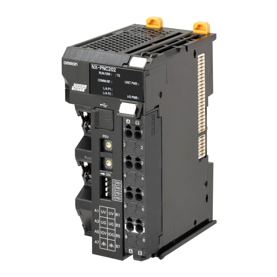
4 Part Names and Functions Indicators There are indicators to show the current operating status of the PROFINET Coupler Unit. NX-PNC202 RUN/ERR COMM/BF Letter Name Function Model number The model number of the PROFINET Coupler Unit is shown. Indicators The current operating status of the PROFINET Coupler Unit is shown. RUN/ERR The Run and Error Status (RUN/ERR) indicator indicates the status of the Unit. - Page 66 4 Part Names and Functions COMM/BF Indicator The Communication / Bus Failure (COMM/BF) indicator indicates the status of the network. Color Status Meaning Green Cyclic data exchange active with a PROFINET IO Controller. Alternating: Device identification when DCP Set/Flush is received.
- Page 67 4 Part Names and Functions UNIT PWR Indicator The UNIT PWR indicator shows the status of the Unit power supply. Color Status Meaning Green Unit power supplied Not lit No Unit power supply IO PWR Indicator The IO PWR indicator shows the status of the IO power supply. Color Status Meaning...
-
Page 68: Hardware Switch Settings
4 Part Names and Functions Hardware Switch Settings This section describes the functions of the hardware switches (i.e., the rotary switches and the DIP switch) on the front panel of the PROFINET Coupler Unit. Rotary Switches Not used. Dip Switches Not used. -
Page 69: Communications Connector And Peripheral Usb Port
4 Part Names and Functions Communications Connector and Periph- eral USB Port This section provides the specifications of the communications connectors and peripheral USB port on the front panel of the PROFINET Coupler Unit. NX-PNC202 RUN/ERR COMM/BF Peripheral USB port Port1 Communications connectors Port2... -
Page 70: Terminal Blocks
4 Part Names and Functions Terminal Blocks The terminal block on the PROFINET Coupler Unit is a removable screwless clamping terminal block that allows you to easily connect and remove the wiring. The Unit power supply, IO power supply, and ground wire are connected to this screwless clamping ter- minal block. - Page 71 4 Part Names and Functions Applicable Terminal Blocks for Each Model The terminal blocks that you can use with each model of the PROFINET Coupler Unit are given in the following table. Terminal block Unit model number Terminal block Number of Ground terminal Terminal current model number...
-
Page 72: Din Track Contact Plate
4 Part Names and Functions DIN Track Contact Plate There is a DIN Track contact plate in the section on the back of the PROFINET Coupler Unit that comes into contact with the DIN Track. This plate is connected internally to the functional ground terminal on PROFINET Coupler Unit. This means that the functional ground terminal will be electrically connected to the DIN Track. -
Page 73: Designing The Power Supply System
Designing the Power Supply Sys- This section describes how to design the power supply system for the Profinet IO Device Terminal. 5-1 Power Supply System and Design Concepts ..... . . 5-2 5-1-1 Power Supply System and Types of Power Supplies . -
Page 74: Power Supply System And Design Concepts
5 Designing the Power Supply System Power Supply System and Design Concepts This section describes the power supply system for a Profinet IO Device Terminal and the design con- cepts. 5-1-1 Power Supply System and Types of Power Supplies Power Supply System Configuration Diagram An example of a power supply system configuration diagram for a Profinet IO Device Terminal is shown below. -
Page 75: Nx-Series Power Supply-Related Units
For the specifications of NX-series power supply-related Units, refer to the NX-series System Units User’s Manual (Cat. No. W523). For information on the most recent lineup of NX Series power sup- ply-related Units, refer to NX-series catalogs or OMRON websites, or ask your OMRON representative. Unit name... - Page 76 5 Designing the Power Supply System Unit name Function Additional IO Power Sup- This NX Unit provides additional IO power supply. ply Unit Use this NX Unit in the following cases. (a) When the IO power supply capacity is insufficient •...
-
Page 77: Design Concepts For Power Supply To The Profinet Io Device Terminal
5 Designing the Power Supply System Unit name Function IO Power Supply Connec- This NX Unit is used when there are not enough IO power supply terminals for the tion Unit connected external devices that are connected to NX Units such as Digital IO Units and Analog IO Units. -
Page 78: Designing The Nx Unit Power Supply System
5 Designing the Power Supply System Designing the NX Unit Power Supply System This section describes how to design the NX Unit power supply to the Profinet IO Device Terminal. 5-2-1 Procedure for Designing the NX Unit Power Supply System The total power consumption from the NX Unit power supply must not exceed the NX Unit power supply capacity of the Unit that supplies the NX Unit power. -
Page 79: Calculation Example For The Nx Unit Power Supply
5 Designing the Power Supply System NX Unit Power Supply Capacity and Restrictions The internal power supply circuits of the PROFINET Coupler Unit or Additional NX Unit Power Sup- ply Unit supply the NX Unit power to the NX Units. The NX Unit power supply capacity does not include the NX Unit power consumption of the PROF- INET Coupler Unit or Additional NX Unit Power Supply Units. - Page 80 5 Designing the Power Supply System Additional Information Excess or insufficiency in the NX Unit power supply capacity can be easily checked when the Unit configuration is created on the Edit IO Device Terminal Configuration Tab Page on the Sys- mac Studio.
-
Page 81: Designing The Io Power Supply System
5 Designing the Power Supply System Designing the IO Power Supply Sys- This section describes how to design the IO power supply to the Profinet IO Device Terminal. 5-3-1 IO Power Supply Method There are the following two methods to supply the IO power supply to the Profinet IO Device Terminal depending on the type and model of the NX Units. -
Page 82: Designing The Io Power Supply From The Nx Bus
5 Designing the Power Supply System 5-3-2 Designing the IO Power Supply from the NX Bus Procedure for Designing the IO Power Supply Make sure that the following design conditions are met when you design the IO power supply from the NX bus. - Page 83 5 Designing the Power Supply System ●The total current consumption ●The total current consumption from the I/O power supply from the I/O power supply ●The total current consumption from the I/O must not exceed the must not exceed the power supply must not exceed the maximum current of the I/O maximum current of the I/O maximum current of the I/O power supply.
- Page 84 5 Designing the Power Supply System Current consumption item Description Current consumption between This is the current that is consumed between the NX Units and the con- the NX Units and the connected nected external devices. external devices For example, this is the current consumed by a Digital Input Unit to supply power to photoelectric sensors or to turn ON the input circuits in the Digital Input Unit.
- Page 85 5 Designing the Power Supply System ● Total current consumption from the Units ● Units that are supplied I/O Example: that are supplied I/O power from the power from the Additional I/O PROFINET Coupler Unit (total for (1) Power Supply Unit to (7) = 4 A) PROFINET Coupler...
-
Page 86: Designing The Io Power Supply From External Sources
5 Designing the Power Supply System power supply systems are to be separated and then perform similar calculations to design the overall system to meet the power supply conditions. 5-3-3 Designing the IO Power Supply from External Sources Unlike supplying power from the NX bus, there is no specific design method for supplying IO power from external sources. - Page 87 5 Designing the Power Supply System Irms τ 5 - 15 NX-series PROFINET Coupler Unit User’s Manual (W623)
-
Page 88: Selecting External Power Supplies And Protective Devices
• Has double or reinforced insulation between the input and output. • Has an output voltage of 24 VDC (20.4 to 28.8 VDC). Recommended Power Supplies: S8JX Series (manufactured by OMRON) Calculating the Required Power Supply Capacity of the Unit Power Supply ... - Page 89 5 Designing the Power Supply System Blocks A block consists of the Unit that supplies the NX Unit power and the range of Units to which that Unit supplies the NX Unit power. For example, in the configuration in the following figure there are two blocks in the Profinet IO Device Terminal: the block with the PROFINET Coupler Unit and the block with the Additional NX Unit Power Supply Unit.
-
Page 90: Selecting The Io Power Supplies
*1. Use an output voltage that is appropriate for the IO circuits of the NX Units and the connected external devices. Recommended Power Supplies: S8JX Series (manufactured by OMRON) Calculating the Required Power Supply Capacity of the IO Power Supply... -
Page 91: Selecting Protective Devices
5 Designing the Power Supply System Selecting Protective Devices Consider the following items when you select protective devices. • Protective device specifications (breaking/fusing, detection characteristics, steady current value, etc.) • Inrush current when power is turned ON • Inrush current when connected external devices turn ON and OFF *1. - Page 92 5 Designing the Power Supply System Installation Locations for Protective Devices Install protective devices for the Unit power supply and IO power supply in the locations that are shown in the following figure. Block that is supplied I/O power from the Additional Block that is supplied I/O power from the PROFINET I/O Power Supply Unit Coupler Unit...
- Page 93 5 Designing the Power Supply System • Using Unwired Unit Power Supply Terminals In this example, the current consumption from each power supply is as follows: Current consumption from Unit power supply: I_unit1 + I_unit2 Lowest rated current Current consumption from IO power supply: I_io1 + I_io2 Lowest rated current Block that is supplied I/O power from the Additional Block that is supplied I/O power from the PROFINET...
- Page 94 5 Designing the Power Supply System • When Total Current Consumption for All Blocks Does Not Exceed the Rated Current In this example, the current consumption from each power supply is as follows: Current consumption from Unit power supply: I_unit1 + I_unit2 Lowest rated current Current consumption from IO power supply: I_io1 + I_io2 ...
-
Page 95: Installation
Installation This section describes how to install the Profinet IO Device Terminal. 6-1 Installing Units ..........6-2 6-1-1 Installation Precautions . -
Page 96: Installing Units
6 Installation Installing Units This section describes how to mount Units to a Profinet IO Device Terminal. 6-1-1 Installation Precautions To increase the reliability of the Profinet IO Device Terminal and take complete advantage of its func- tionality, observe the following precautions. Installation Location Do not install the Profinet IO Device Terminal in the following locations. - Page 97 6 Installation Control panel PROFINET Slave Terminal Louver Accessibility for Operation and Maintenance • To ensure safe access for operation and maintenance, separate the Profinet IO Device Terminal as much as possible from high-voltage equipment and power machinery. • If will be easy to operate the Profinet IO Device Terminal if it is mounted at a height of 1.0 to 1.6 m above the floor.
- Page 98 6 Installation Wiring Ducts Whenever possible, route IO wiring through wiring ducts. Install mounting bases so that it is easy to wire the IO Units through ducts. It is handy to have the ducts at the same height as the Profinet IO Device Terminal. Duct 20 mm min PROFINET...
- Page 99 6 Installation Routing Wiring Ducts Install the wiring ducts at least 20 mm away from the tops of the devices and any other objects (e.g., top of the panel, other wiring ducts, structural supports, and components) to provide enough space for air circulation and replacement of Units.
-
Page 100: Preparations For Installation
You must install the PROFINET Coupler Unit and NX Units on a DIN Track. The following products are recommended. Name Model Manufacturer Remarks 35-mm DIN PFP-50N OMRON Corporation • Length: 50 cm Track • Material: Aluminum • Surface treatment: Insulated PFP-100N OMRON Corporation • Length: 100 cm •... - Page 101 6 Installation DIN Tracks PFP-100N/50N DIN Track 7.3±0.15 35±0.3 27±0.15 15(5) 1000(500)* *1 PFP-50N dimensions are given in parentheses. NS 35/7,5 PERF R0.8 R0.8 NS 35/15 PERF 15° R1.25 R1.25 End Plate PFP-M (Two) CLIPFIX 35 (Two) 6 - 7 NX-series PROFINET Coupler Unit User’s Manual (W623)
-
Page 102: Installation Orientation
6 Installation 6-1-3 Installation Orientation a Profinet IO Device Terminal can be installed in any of the following six orientations. (A) is the upright installation direction and (B) to (F) are installation directions other than upright. Down However, there are restrictions on the installation orientation of the PROFINET Coupler Unit due to the ambient operating temperature and the NX Unit power supply capacity. -
Page 103: Installing The Profinet Coupler Unit
6 Installation 6-1-4 Installing the PROFINET Coupler Unit This section describes how to install the PROFINET Coupler Unit. Precautions for Safe Use • Always turn OFF the power supply before installing the Unit. If the power supply is not OFF, the Unit may malfunction or may be damaged. •... - Page 104 6 Installation Install the DIN Track. • Using a PFP-50N/100N DIN Track Use one M4 screw for each three holes in the DIN Track. Ensure the head of each screw is at least 2 mm below the top of the DIN Track to prevent damage to units. There must be a screw for each interval of 105 mm or less.
- Page 105 6 Installation Press the PROFINET Coupler Unit firmly against the DIN Track until you hear the DIN Track mounting hook lock into place. After you mount the PROFINET Coupler Unit, check to be sure that it is securely mounted on the DIN Track.
-
Page 106: Installing And Connecting Nx Units
6 Installation 6-1-5 Installing and Connecting NX Units This section describes how to mount NX Units to the PROFINET Coupler Unit and how to connect NX Units to each other. Precautions for Safe Use • Always turn OFF the power supply before mounting the NX Units. If the power supply is not OFF, the Unit may malfunction or may be damaged. - Page 107 6 Installation Unit hookup guides Unit hookup guides Slide the NX Unit in on the hookup guides. Press the NX Unit with a certain amount of force against the DIN Track until you hear the DIN Track mounting hook lock into place. When you mount the NX Unit, it is not necessary to release the DIN track mounting hook on the NX Unit.
- Page 108 6 Installation Unit hookup guides Unit hookup guides Slide the NX Unit in on the hookup guides. Press the NX Unit with a certain amount of force against the DIN Track until you hear the DIN Track mounting hook lock into place. When you mount the NX Unit, it is not necessary to release the DIN track mounting hook on the NX Unit.
-
Page 109: Mounting The End Cover
6 Installation 6-1-6 Mounting the End Cover Always mount an End Cover to the end of the IO Device Terminal. Precautions for Safe Use • Always turn OFF the power supply before mounting the End Cover. If the power supply is not OFF, the Unit may malfunction or may be damaged. -
Page 110: Mounting The End Plates
IO Device Terminal to secure the IO Device Terminal. If you do not secure it, the Profinet IO Device Terminal may be damaged or malfunction. Using PFP-M (OMRON) To mount an End Plate, 1) hook the bottom of it on the bottom of the DIN Track and 2) rotate the End Plate to hook the top of it on the top of the DIN Track. -
Page 111: Attaching Markers
Markers can be attached to PROFINET Coupler Units, NX Units, and terminal blocks on NX Units to identify them. The plastic markers made by OMRON are installed for the factory setting. The ID information can be written on them. Commercially available markers can also be installed. -
Page 112: Removing Units
DEK 5/8 Special marker printer UM EN BLUEMARK X1 PrintJet PRO The markers made by OMRON cannot be printed on with commercially available special printers. 6-1-9 Removing Units Precautions for Safe Use Always turn OFF the power supply before removing any Unit. - Page 113 6 Installation Remove the Unit with either (a) or (b) below. (a) For a PROFINET Coupler Unit, place your fingers on the protrusions on the PROFINET Coupler Unit and pull it straight forward. (b) For an NX Unit, place your fingers on the protrusions on more than one NX Unit, including the NX Unit to remove, and pull the NX Units straight forward.
-
Page 114: Assembled Appearance And Dimensions
6 Installation 6-1-10 Assembled Appearance and Dimensions Installation Dimensions End Cover Coupler Unit End Plate 0.55 NX Units End Plate DIN Track 104.5 65.2 W+(C)+(C) (Unit: mm) (Unit: mm) *1. The dimension is 1.35 mm for NX Units with 12-mm widths with lot numbers through December 2014. W: Width of the Profinet IO Device Terminal W + (C) + (C): Width of the Profinet IO Device Terminal including the End Plates Dimension from the... - Page 115 6 Installation Calculation Example for the Configuration Width of a Profinet IO Device Ter- minal NX Units: Digital Input Units with 4 inputs each NX Units: End Cov Temperature Input Units PROFINET Coupler Unit with 4 inputs each The widths of the Units in the example Profinet IO Device Terminal configuration and the total con- figuration width are given below.
- Page 116 6 Installation Installation Height The installation height of the Profinet IO Device Terminal depends on the model of DIN Track and on the models of NX Units that are mounted. Also, additional space is required for the cables that are connected to the Unit. Allow sufficient depth in the control panel and allow extra space when you mount the Profinet IO Device Terminal.
-
Page 117: Control Panel Installation
6 Installation Control Panel Installation To ensure system reliability and safety, the system must be designed and configured according to the installation environment (temperature, humidity, vibration, shock, corrosive gases, overcurrent, noise, etc.). 6-2-1 Temperature Panels have been reduced in size due to space-saving and miniaturization in devices and systems, and the temperature inside the panel may be at least 10 to 15°C higher than outside the panel. - Page 118 6 Installation Forced Ventilation by Fan at Top of Panel PROFINET IO Device PROFINET IO Device Air filter Forced Ventilation Method Forced Air Circulation by Fan in Closed Panel PROFINET IO Device PROFINET IO Device Forced Circulation Method ...
-
Page 119: Humidity
6 Installation 6-2-2 Humidity Rapid temperature changes can cause condensation to occur, resulting in malfunctioning due to short-circuiting. When there is a possibility of this occurring, take measures against condensation, such as leaving the Profinet IO Device Terminal power ON at night or installing a heater in the control panel to keep it warmer. - Page 120 6 Installation Example of Recommended Equipment Arrangement PROFINET IO Device Control panel Control panel High-voltage power panel Example of Poor Equipment Arrangement PROFINET IO Device Control panel Control panel High-voltage power panel Examples of Equipment Arrangement in Panel with High-voltage Devices Arrangement of Profinet IO Device Terminal and Cables Observe the following points.
- Page 121 6 Installation • Keep the wiring between the transformer and the Profinet IO Device Terminal as short as possible, twist the wires well, and keep the wiring separate from high-voltage and power lines. Supplying IO Power from the NX Bus Power circuits Power supply for general operations circuits I/O power supply for PROFINET IO Device...
- Page 122 6 Installation • Never bundle IO cables with high-voltage or power lines, and do not route them in close proximity or parallel to such lines. If output signal lines must be routed in close proximity to such lines, place them in separate ducts or conduits.
- Page 123 6 Installation Partition Signal Signal Signal Power cables cables cables supply cables (group A) (group C) (group B) Signal cables Signal cables Signal cables Power supply cables Power supply cables Partitioning Methods for Signal and Power Supply Cables • To avoid overheating the conduits when using conduits for wiring, do not place wires for a single circuit in separate conduits.
-
Page 124: Grounding
6 Installation High-voltage power panel Metal tubing Power lines Power lines 200 mm PROFINET PROFINET IO Device IO Device Ground to 100 Ω or less 200 mm Example: Separating PROFINET IO Device from Power Lines Other Precautions Some models of Digital Input Units and Digital Output Units have polarity. Make sure that you wire the polarity correctly. - Page 125 6 Installation Grounding Methods PROFINET PROFINET PROFINET IO Device IO Device IO Device DIN Track DIN Track DIN Track Other Other Other device device device Ground to 100 Ω or less (c) Common Ground: Incorrect (a) Independent Grounds: Best (b) Common Ground: Acceptable If the DIN Track is made of steel and the surface is not treated to produce an insulating material, you can omit grounding the functional ground terminal on any Unit that has one, as shown in the follow-...
- Page 126 6 Installation 6 - 32 NX-series PROFINET Coupler Unit User’s Manual (W623)
- Page 127 Wiring This section describes how to wire the Profinet IO Device Terminal. 7-1 PROFINET Network Wiring ........7-2 7-1-1 Installation Precautions .
-
Page 128: Profinet Network Wiring
7 Wiring PROFINET Network Wiring This section describes how to install the PROFINET network. 7-1-1 Installation Precautions Basic precautions for the installation of PROFINET networks are provided below. Precautions when Installing a Network • When you install a Profinet network, take sufficient safety precautions and perform the installation according to all applicable standards and specifications. -
Page 129: Pin Arrangement Of Communications Connectors On The Profinet Coupler Unit
7 Wiring Precautions for Safe Use • Double-check all switches and other settings and double-check all wiring to make sure that they are correct before turning ON the power supply. Use the correct wiring parts and tools when you wire the system. •... -
Page 130: Connecting Communications Cables And Connectors
7 Wiring 7-1-4 Connecting Communications Cables and Connectors Use straight connections for the communications cables and connectors, as shown below. Wire color Wire color Pin No. Pin No. White-Green White-Green Green Green White-Orange White-Orange Blue Blue White-Blue White-Blue Orange Orange White-Brown White-Brown Brown... - Page 131 7 Wiring PROFINET IO Controller Unit Communications cable PROFINET IO Devices Last PROFINET IO Device Precautions for Correct Use • The cable between any two nodes (L1, L2 ... Ln) must be 100 m or less. • Do not exceed the ranges that are given in the specifications for the communications dis- tance and number of connected Units.
-
Page 132: Connecting The Power Supply And Ground Wires
7 Wiring Connecting the Power Supply and Ground Wires This section describes how to wire the power supplies and ground the Profinet IO Device Terminal. 7-2-1 Wiring the PROFINET Coupler Unit The wiring of the power supply and ground to the PROFINET Coupler Unit is shown in the following fig- ure. -
Page 133: Wiring The Power Supply To The Profinet Io Device Terminal
7 Wiring Functional Ground Terminals These are the functional ground terminals. Connect the ground wire to one of these terminals. The details are given in the following table. Terminal number indication Terminal symbol Description A7 or B7 Connect the ground wire to either the A7 or B7 ter- minal. - Page 134 7 Wiring DIN Track Contact Plates A Unit that has a ground terminal also has a DIN Track contact plate on the back of the Unit. Unit side Ground terminal DIN Track contact plate Connected inside the Unit. The DIN Track contact plate is connected internally to the ground terminal on the Unit. This means that the ground terminal will be electrically connected to the DIN Track.
- Page 135 If the ground wire for the PROFINET Coupler Unit or an NX Unit with a ground terminal is shared with power equipment, noise will adversely affect the Units. You can use OMRON NX-AUX01 DIN Track Insulation Spacers with PFP-50N or PFP-100N DIN Tracks to isolate a Profinet IO Device Terminal from the control panel.
- Page 136 Screws, M4×10 DIN Track Control panel • DIN Track Insulation Spacers NX-AUX01 (OMRON Corporation) 14.8 Precautions for Correct Use If you use DIN Track Insulation Spacers to install a Profinet IO Device Terminal, the height will be increased by approximately 10 mm. Make sure that the Profinet IO Device Terminal and connecting cables do not come into contact with other devices.
-
Page 137: Precautions For Wiring The Profinet Io Device Terminal Together With Computers And Other Peripheral Devices
7 Wiring 7-2-4 Precautions for Wiring the PROFINET IO Device Terminal Together with Computers and other Peripheral Devices Caution When you connect a computer or other peripheral device to the following Unit, either ground the 0-V side of the external power supply (i.e. Unit power supply) or do not ground it at all. •... - Page 138 7 Wiring WARNING Make sure that the voltages and currents that are input to the Units and PROFINET Coupler Unit are within the specified ranges. Inputting voltages or currents that are outside of the specified ranges may cause failure or fire. Applicable Wires The wires that you can connect to the screwless clamping terminal block are twisted wires, solid wires, and ferrules that are attached to the twisted wires.
- Page 139 7 Wiring Applica- ble wire Terminal Manufac- Ferrule Crimping tool types turer model (AWG)) Terminals Weidmuller H0.14/12 0.14 (#26) Weidmuller (The figure in parentheses is the appli- other than cable wire size.) H0.25/12 0.25 (#24) ground ter- H0.34/12 0.34 (#22) PZ6 Roto (0.14 to 6 mm , AWG26 to 10) minals...
- Page 140 7 Wiring Precautions for Correct Use • Use cables with suitable wire sizes for the carrying current. There are also restrictions on the current due to the ambient temperature. Refer to the manuals for the cables and use the cables correctly for the operating environment. •...
- Page 141 7 Wiring Recommended screwdriver Model Manufacturer SZF 0-0,4X2,5 Phoenix Contact Connecting Ferrules Insert the ferrule straight into the terminal hole. It is not necessary to press a flat-blade screwdriver into the release hole. Ferrule After you make a connection, make sure that the ferrule is securely connected to the terminal block. ...
- Page 142 7 Wiring Remove the flat-blade screwdriver from the release hole. After you make a connection, make sure that the twisted wire or the solid wire is securely connected to the terminal block. Precautions for Safe Use • Do not press the flat-blade screwdriver straight into the release hole. Doing so may break the terminal block.
- Page 143 7 Wiring Securing Wires It is necessary to secure wires to the screwless clamping terminal block depending on the wire types that are used or the current flows on the wires. The following table gives the necessity for securing wires. Terminals Wire type Twisted wires...
- Page 144 7 Wiring Bundle the wires with a cable tie and secure them to the screwless clamping terminal block. Secure wires within the range of 30 mm from the screwless clamping terminal block. 30 mm 7 - 18 NX-series PROFINET Coupler Unit User’s Manual (W623)
- Page 145 7 Wiring Removing Wires Use the following procedure to remove the wires from the terminal block. The removal method is the same for ferrules, twisted wires, and solid wires. If wires are secured firmly to the terminal block, release them first. Press the flat-blade screwdriver diagonally into the release hole.
- Page 146 7 Wiring Precautions for Safe Use • Do not press the flat-blade screwdriver straight into the release hole. Doing so may break the terminal block. • When you insert a flat-blade screwdriver into a release hole, press it down with a force of 30 N max.
- Page 147 7 Wiring Attaching a Terminal Block Mount the terminal block hook on the guide at the bottom of the PROFINET Coupler Unit, lift up the terminal block, and press in on the top of the terminal block until you hear it engage. The terminal block will click into place on the Unit.
- Page 148 7 Wiring Types of Coding Pins There are two types of Coding Pins, both with their own unique shape: one for terminal blocks and one for Units. Three pins come with each runner. For Unit For terminal block Runners Coding Pins (Use this part.) Use the following Coding Pins.
- Page 149 7 Wiring Unit Terminal block Holes used by Holes used by OMRON OMRON Holes for incorrect Holes for incorrect attachment prevention attachment prevention (pin locations) (pin locations) ○: Pin inserted Pin locations for Pin locations for Unit terminal block Pattern No.1...
- Page 150 Precautions for Correct Use • OMRON uses the holes other than No. 1 to 6 in the figure on the previous page. If you insert a Coding Pin into one of the holes used by OMRON on the terminal block side, it would be impossible to mount the terminal block on a Unit.
- Page 151 7 Wiring Unit 7 - 25 NX-series PROFINET Coupler Unit User’s Manual (W623)
-
Page 152: Connecting Usb Cable
7 Wiring Connecting USB Cable The PROFINET Coupler Unit can be connected directly to a computer in which the Sysmac Studio is installed through a USB cable. Connection Method Use a commercially available USB certified cable to connect the computer in which the Sysmac Studio is installed to the peripheral USB port on the PROFINET Coupler Unit. - Page 153 7 Wiring Making Settings with the Sysmac Studio The connection between the PROFINET Coupler Unit and computer is set up with the Sysmac Studio. Refer to 2-3-1 Connection Method and Procedures on page 2-9 for the procedure to connect to the Sysmac Studio.
-
Page 154: Wiring External Signal Lines
7 Wiring Wiring External Signal Lines Refer to the sections on wiring in the user’s manuals for individual NX Units for information on wiring the external IO signal lines between the external devices and the NX Units. For precautions on wiring in control panels, refer to 6-2 Control Panel Installation on page 6-23. 7 - 28 NX-series PROFINET Coupler Unit User’s Manual (W623) -
Page 155: Profinet Communications
PROFINET Communications This section provides an introduction to PROFINET communications. 8-1 Communication protocols ........8-2 8-1-1 RT and IRT . -
Page 156: Communication Protocols
8 PROFINET Communications Communication protocols PROFINET uses Ethernet and TCP, UDP and IP as basis for the communication between the devices. 8-1-1 RT and IRT The TCP/IP and UDP/IP communication protocols apply a considerable amount of control overhead which will slow down data transmission speed which is required for PROFINET applications. To facilitate Real-Time capabilities for data exchange, the PROFINET uses a specific protocol of Real-Time (RT) Communication. -
Page 157: Setting Up The Profinet Coupler Unit
Setting Up the PROFINET Coupler Unit This section describes the procedures used to set up the PROFINET Coupler Unit. 9-1 Settings and Setting Procedures ....... . . 9-2 9-1-1 Items to Set . -
Page 158: Settings And Setting Procedures
Configuration and Operation Sysmac Stu- tion settings of the NX Units and PROFINET Coupler Unit using Settings PROFINET Data This data is set using a configuration tool such as the OMRON Network Configurator. Setting Description Setting PROFINET IO Device Supported... - Page 159 9 Setting Up the PROFINET Coupler Unit PROFINET IO Controller PROFINET IO port Communications cable Ethernet cables PROFINET Coupler Unit Peripheral USB port with PROFINET IO Devices Third party PROFINET IO Controller software Ethernet switch Configure PROFINET IO network. E.g. PROFINET IO Device name, IP Address, IO data.
-
Page 160: Io Device Terminal Parameters
9 Setting Up the PROFINET Coupler Unit 9-1-2 IO Device Terminal Parameters Parameters must be set to ensure that the IO Device Terminal operates as intended and performs data exchange with other PROFINET devices. The settings are listed in the following table. Setting Description IO Device Termi-... -
Page 161: Setting Io Device Terminal Parameters
9 Setting Up the PROFINET Coupler Unit Setting IO Device Terminal Parame- ters This section describes how to set the IO Device Terminal parameters with Support Software. The Sys- mac Studio is used as an example. For Support Software other than the Sysmac Studio, refer to the operation manual for the Support Soft- ware that you are using. - Page 162 9 Setting Up the PROFINET Coupler Unit Data Setting Settable Description Default range Device name This is the name of the PROFINET Coupler Unit. E *** (* is a serial number from Use the PROFINET Configuration Edit Tab Page to 001).
-
Page 163: Setting The Nx Unit Configuration Information
9 Setting Up the PROFINET Coupler Unit NX Units Data Name Settable Description Default range Device name The name of the NX Unit. N* (Where * is a serial number from 1) Model name This is the model number of the NX Unit. Product name This is the product name. - Page 164 9 Setting Up the PROFINET Coupler Unit The Edit IO Device Terminal Configuration Tab Page is displayed. Drag the NX Unit from the Toolbox to the Edit Configuration Pane and drop it on the IO Device Terminal. Item Description Edit Configuration Pane You can edit the Unit configuration information for the IO Device Terminal here.
- Page 165 9 Setting Up the PROFINET Coupler Unit Precautions for Correct Use If you turn ON the power to a Profinet IO Device Terminal before you create or transfer the Unit configuration information to the Profinet IO Device Terminal, the TS indicator on the front panel of the PROFINET Coupler Unit will flash green at 0.5-second intervals.
-
Page 166: Unit Operation Settings
9 Setting Up the PROFINET Coupler Unit 9-2-3 Unit Operation Settings Unit Operation Settings for the PROFINET Coupler Unit The operation settings of the PROFINET Coupler Unit are listed below. Setting Setting range Default Description Fail-soft Operation Set- Stop or Fail-soft Stop Set whether to use fail-soft operation for the IO ting/Fail-soft Operation... -
Page 167: Unit Application Data
9 Setting Up the PROFINET Coupler Unit Unit Operation Settings for the NX Unit The settings that are available depend on the type of the NX Unit. For example, Digital Input Units have a setting for the input filter value, and Digital Output Units have a setting for the output value at load rejection. -
Page 168: Sysmac Studio Functions Used As Required
9 Setting Up the PROFINET Coupler Unit 9-2-5 Sysmac Studio Functions Used as Required You can use the following functions on the Sysmac Studio. • Getting NX Unit serial numbers • Comparing and merging with actual Unit configuration of the IO Device Terminal •... - Page 169 9 Setting Up the PROFINET Coupler Unit Getting NX Unit Serial Numbers If the serial number check method that is set in the PROFINET Coupler Unit is set to Setting = Actual device, you must download the Unit configuration information in which the serial numbers for the NX Units are set to the PROFINET Coupler Unit.
- Page 170 9 Setting Up the PROFINET Coupler Unit Uploading IO Device Terminal Settings through the USB Port on the PROFINET Coupler Unit You can connect the Sysmac Studio to the USB port on the PROFINET Coupler Unit and transfer the settings information to the Sysmac Studio from the IO Device Terminal. With some Support Software, you can connect through Ethernet or with any other method except for a USB port.
- Page 171 9 Setting Up the PROFINET Coupler Unit Adding Additional Coupler Units A Sysmac Studio project can include multiple Coupler Unit device configurations. Use the following procedure to add additional Coupler Unit configurations to a project when necessary. Right-click the IO Device Terminal icon and select Add Device or select Insert - IO Device Terminal - PROFINET Coupler.
-
Page 172: Transferring And Comparing Settings
9 Setting Up the PROFINET Coupler Unit Transferring and Comparing Settings This section describes how to transfer and compare IO Device Terminal settings that you set on the Support Software. The Sysmac Studio is used as an example. For Support Software other than the Sysmac Studio, refer to the operation manual for the Support Soft- ware that you are using. - Page 173 9 Setting Up the PROFINET Coupler Unit Click the Yes button. The specified data is transferred. Precautions for Correct Use • The PROFINET IO Controller may detect an error when the IO Device Terminal is restarted after the IO Device Terminal setting information is transferred with a direct USB connection between the Sysmac Studio and PROFINET Coupler Unit.
-
Page 174: Comparing Settings
9 Setting Up the PROFINET Coupler Unit 9-3-2 Comparing Settings To compare the IO Device Terminal settings, connect the Sysmac Studio to the USB port of the PROF- INET Coupler Unit to compare. Use the following procedure. Refer to 9-2-5 Sysmac Studio Functions Used as Required on page 9-12 to compare the Unit configu- ration. -
Page 175: Setting Profinet Io Device Name
9 Setting Up the PROFINET Coupler Unit Setting PROFINET IO Device Name In order to identify the PROFINET Coupler Unit on the PROFINET IO network, it needs to be assigned a PROFINET IO Device Name. This Device Name is an ASCII string, which is written to the IO Devices by the third party PROFINET IO Controller configuration software. -
Page 176: Setting Profinet Io Data
The GSDML file is available at the OMRON website (https://industrial.omron.eu/en/products/NX-PNC202#ddf) for download. After installation the OMRON NX-PNC202 will appear in the IO Device catalogue. Add the PROFINET Coupler Unit to the network configuration in the tool. Refer to the IO Controller manual for details on how to build up the Profinet IO network including the PROFINET Coupler. - Page 177 9 Setting Up the PROFINET Coupler Unit Configure the IO Modules used for the PROFINET Coupler unit. After adding the PROFINET Coupler to the network, the following IO Modules will be assigned to the IO Controller by default. Num- Slot Subslot Allocable Sub module Default...
- Page 178 9 Setting Up the PROFINET Coupler Unit Details of IO Data in the PROFINET Coupler Unit This section describes the IO data in detail. Unit Status Data name Description Unit Status This indicates the status conditions of the IO Device Terminal. The following table shows the structure of the bits in the Unit status.
- Page 179 9 Setting Up the PROFINET Coupler Unit Name Description Reserved Reserved Reserved Reserved Reserved Reserved Reserved Communication Coupler unit and Ethernet network status This is the combination of the Unit Status and the Ethernet Network Status. Refer to bullets above for details. ...
- Page 180 9 Setting Up the PROFINET Coupler Unit NX Unit IO Data Active Status Data name Description NX Unit IO Data Active Sta- This status tells whether the NX Units can process IO data communications. tus 63 The status is acquired for as many NX Units as the numeric suffix at the end of the data name.
- Page 181 9 Setting Up the PROFINET Coupler Unit NX Error Clear The Sysmac Error Clear provides the clear feature of the error status. It is defined as an Unsigned16, as bits. Name Description Sysmac Error Clear The Sysmac Error is cleared when the coupler detects the rising edge of this bit from 0 to 1.
-
Page 182: Parameter Settings Of The Profinet Coupler Unit
9 Setting Up the PROFINET Coupler Unit 9-5-2 Parameter Settings of the PROFINET Coupler Unit Set the detailed parameter related to the PROFINET Coupler Unit. Select the properties of the Unit Parameter module to be able to set the detailed parameter for the PROFINET Coupler Unit. -
Page 183: Nx Unit Io Allocation
9 Setting Up the PROFINET Coupler Unit NX Unit IO Allocation The detail input and output allocation is determined in the Sysmac Studio software. Use the following information to assign input and output data in the third party IO Controller. 9-6-1 Basic IO Mapping The numbers used to identify NX Units in an IO Device Terminal are called Unit Numbers. - Page 184 9 Setting Up the PROFINET Coupler Unit • One block of mapped output data and one block of mapped input data are maintained in the PROFINET Unit. • Refer to 9-6 NX Unit IO Allocation on page 9-27 for details about IO allocation and PROF- INET Coupler Unit Status.
-
Page 185: Sysmac Studio Io Allocation Functions
9 Setting Up the PROFINET Coupler Unit 9-6-2 Sysmac Studio IO Allocation Functions The Sysmac Studio provides a display of the IO allocation for the IO Device Terminal configuration. This display shows the bit offset and size of the data allocated for a specific configuration as well as other important information. -
Page 186: Endian
9 Setting Up the PROFINET Coupler Unit IO Allocation Display The IO allocation display area includes the following information. Item Description Input Tab The overview of the input IO allocation. Output Tab The overview of the output IO allocation. Position The IO Device Terminal Unit mounting location with corresponding Unit number. - Page 187 I/O Refreshing This section describes I/O refreshing for the PROFINET Coupler Unit. 10-1 Introduction to I/O Refreshing for PROFINET IO Devices ... . 10-2 10-2 Communications Performance ........10-3 10-2-1 I/O Response Time .
-
Page 188: Introduction To I/O Refreshing For Profinet Io Devices
10 I/O Refreshing 10-1 Introduction to I/O Refreshing for PROFINET IO Devices This section introduces I/O refreshing for NX-series PROFINET IO Devices. The PROFINET IO Controllers perform I/O refreshing cyclically with the NX Units in a PROFINET IO Device through PROFINET communications and the NX bus. The following four cycles affect the oper- ation of I/O refreshing between the PROFINET IO Controllers and the NX Units in a PROFINET IO Device. -
Page 189: Communications Performance
10 I/O Refreshing 10-2 Communications Performance This section describes the characteristics of PROFINET communications with PROFINET IO Devices connected to a PROFINET IO Controller. Use this section for reference when planning operations that require precise I/O timing. The equations provided here are valid under the following conditions: •... - Page 190 10 I/O Refreshing Minimum I/O Response Time The minimum I/O response time (T ) can be calculated with the following formula. nxb_cycle rt_in rt_out nxb_cycle PROFINET rt_out rt_in PROFINET Coupler Unit nxb_cycle nxb_cycle NX Input Unit NX Output Unit : NX Input Unit switching response time : NX bus communication time nxb_cycle...
- Page 191 10 I/O Refreshing Maximum I/O Response Time The maximum I/O response time (T ) can be calculated with the following formula. + (T x 5) + (T x 4) + (T x 2) + T nxb_cycle PROFINET PROFINET Coupler Unit nxb_cycle nxb_cycle nxb_cycle...
- Page 192 10 I/O Refreshing 10 - 6 NX-series PROFINET Coupler Unit User’s Manual (W623)
- Page 193 PROFINET Coupler Unit Func- tions This section describes the functions of the PROFINET Coupler Unit when it is used in a Profinet IO Device Terminal. 11-1 Functions ..........11-3 11-2 NX Unit Mounting Settings .
- Page 194 11 PROFINET Coupler Unit Functions 11-8 Monitoring Total Power-ON Time ....... 11-30 11-8-1 Overview .
-
Page 195: Functions
11 PROFINET Coupler Unit Functions 11-1 Functions The functions of the PROFINET Coupler Unit when it is used in a Profinet IO Device Terminal are listed below. Function Overview Reference Setting the IO Device Termi- This function is used to read and set the IO Device Termi- Section 9 Setting Up nal parameters from the Sysmac Studio. -
Page 196: Nx Unit Mounting Settings
11 PROFINET Coupler Unit Functions 11-2 NX Unit Mounting Settings This section describes the NX Unit mounting function when the disabled setting is used. 11-2-1 Introduction The disabled setting is used to register NX Units that are not connected to the actual configuration but will be added at a later time in the Unit configuration information as unmounted Units. -
Page 197: Applications
11 PROFINET Coupler Unit Functions 11-2-2 Applications For example, if you use this function in the following cases, you do not have to modify the user pro- gram. • When you plan to add Units in the future • When a specific Unit is temporarily unavailable, such as when commissioning the system •... -
Page 198: Setting Nx Units As Unmounted Units
11 PROFINET Coupler Unit Functions 11-2-4 Setting NX Units as Unmounted Units You use the Sysmac Studio to set NX Units as unmounted Units. The operations are described by using the Sysmac Studio as an example. For Support Software other than the Sysmac Studio, refer to the operation manual for the Support Software that you are using. - Page 199 11 PROFINET Coupler Unit Functions In the Unit Setting pane, set the NX Unit Mounting Setting to Disabled. The selected NX Unit is set as an unmounted Unit. To change an NX Unit that is set as an unmounted Unit to a mounted NX Unit, set the NX Unit Mounting Setting to Enabled in step 2.
-
Page 200: Event Logs
11 PROFINET Coupler Unit Functions 11-3 Event Logs The Profinet IO Device Terminal supports the event logs to perform troubleshooting. This section describes event logging for PROFINET Coupler Unit. 11-3-1 Introduction The Profinet IO Device Terminal records events, such as errors and status changes, that occur in the Profinet IO Device Terminal. -
Page 201: Detailed Information On Event Logs
11 PROFINET Coupler Unit Functions 11-3-2 Detailed Information on Event Logs This section describes the event logs in detail. Where Events Are Stored Events that occur in the Profinet IO Device Terminal are stored as described below. Unit where event occurred Where events are stored PROFINET Coupler Unit In the PROFINET Coupler Unit... - Page 202 11 PROFINET Coupler Unit Functions Number of Records Each event log can contain the following number of records. If the number of events exceeds this num- ber, the oldest events are overwritten. Unit type Event log NX Unit PROFINET Coupler category Units that store events in the Units that store their own...
-
Page 203: Reading Event Logs
11 PROFINET Coupler Unit Functions You can change the level assigned to some events. Refer to 11-6 Changing Event Levels on page 11-24. 11-3-3 Reading Event Logs Use the following procedure to read the event log. The operations are described by using the Sysmac Studio as an example. - Page 204 11 PROFINET Coupler Unit Functions Additional Information • The NX Unit numbers that are displayed as the source in the event log are the NX Unit num- bers in the current Unit configuration. They are not necessarily the NX Unit numbers at the time that the event occurred.
-
Page 205: Clearing Event Logs
11 PROFINET Coupler Unit Functions 11-3-4 Clearing Event Logs You can clear the event logs in the Profinet IO Device Terminal. This section describes how to clear the event logs. Specifying the Scope of Event Logs to Clear You can specify whether to clear events from the entire Profinet IO Device Terminal, the PROFINET Coupler Unit, or the NX Units. - Page 206 11 PROFINET Coupler Unit Functions In the Select the Display Target Area of the Controller Event Log Tab Page, select the Units to clear and click the Clear button. A confirmation dialog box is displayed. Click the Yes button. The selected events are cleared. 11 - 14 NX-series PROFINET Coupler Unit User’s Manual (W623)
-
Page 207: Exporting The Event Log
11 PROFINET Coupler Unit Functions 11-3-5 Exporting the Event Log You can export the contents of the event log to a CSV file. The event log for the PROFINET Coupler Unit and NX Units is displayed as part of the Controller event log. -
Page 208: Clearing All Memory
11 PROFINET Coupler Unit Functions 11-4 Clearing All Memory This section describes how to clear all memory in the PROFINET Coupler Unit. 11-4-1 Introduction The clear all memory function of the Sysmac Studio initializes various setting information in the Profinet IO Device Terminal to the default settings, such as the Unit configuration information and the IO alloca- tion information. - Page 209 11 PROFINET Coupler Unit Functions Status after Clear All Memory operation for each specification Data Entire Profinet IO Device PROFINET Coupler Unit NX Unit Terminal Unit application Refer to the manual for each Refer to the manual for each data NX Unit for the operating NX Unit for the operating specifications when the Clear...
-
Page 210: Procedure For Clearing All Memory
11 PROFINET Coupler Unit Functions 11-4-3 Procedure for Clearing All Memory This section provides the procedure for the Clear All Memory operation. The operations are described by using the Sysmac Studio as an example. For Support Software other than the Sysmac Studio, refer to the operation manual for the Support Software that you are using. - Page 211 11 PROFINET Coupler Unit Functions Make an area selection for coupler and click Execute. An execution confirmation dialog box is displayed. Click the Yes button. After the memory is cleared, an automatic restart occurs and the memory all cleared dialog box is displayed.
- Page 212 11 PROFINET Coupler Unit Functions Clearing All Memory for NX Unit Go online, right-click the NX Unit in the Edit IO Device Terminal Configuration Tab Page, and select Clear All Memory. A Clear All Memory Dialog Box is displayed. 11 - 20 NX-series PROFINET Coupler Unit User’s Manual (W623)
- Page 213 11 PROFINET Coupler Unit Functions Make an area selection for coupler and click Execute. An execution confirmation dialog box is displayed. Click the Yes button. After the memory is cleared, an automatic restart occurs and the memory all cleared dialog box is displayed.
-
Page 214: Restarting
11 PROFINET Coupler Unit Functions 11-5 Restarting This section describes restarting a Profinet IO Device Terminal. 11-5-1 Introduction The restart function is used to apply changes to settings with the Sysmac Studio or by executing instructions without cycling the Unit power supply to the Profinet IO Device Terminal. 11-5-2 Details on Restarting This section describes the types of restarts: Restarting the IO Device Terminal and restarting individual NX Units. -
Page 215: Procedure For Restarting
11 PROFINET Coupler Unit Functions 11-5-3 Procedure for Restarting The Sysmac Studio is used as an example to describe the operation to restart a Unit with Support Soft- ware. For Support Software other than the Sysmac Studio, refer to the operation manual for the Sup- port Software that you are using. -
Page 216: Changing Event Levels
11 PROFINET Coupler Unit Functions 11-6 Changing Event Levels This section describes changing event levels for the PROFINET Coupler Unit. 11-6-1 Introduction You can change the event levels that are assigned to each Controller event. 11-6-2 Details on Changing Event Levels Unit of Event Level Settings Levels are set for each event in each Unit. -
Page 217: Procedure To Change An Event Level
11 PROFINET Coupler Unit Functions 11-6-3 Procedure to Change an Event Level Use the Sysmac Studio to change an event level. The operations are described by using the Sysmac Studio as an example. For Support Software other than the Sysmac Studio, refer to the operation man- ual for the Support Software that you are using. - Page 218 11 PROFINET Coupler Unit Functions After you make the change, go online and click the Transfer to Unit button to transfer the change to the Controller. The specified event level is changed. There are no events for the PROFINET Coupler Unit for which you can change the event level. 11 - 26 NX-series PROFINET Coupler Unit User’s Manual (W623)
-
Page 219: Fail-Soft Operation
11 PROFINET Coupler Unit Functions 11-7 Fail-soft Operation This section describes the fail-soft operation for PROFINET Coupler Unit. 11-7-1 Overview This function allows the PROFINET Coupler Unit to start or continue IO refreshing only with the NX Units that can operate normally when an error occurs for the Profinet IO Device Terminal. End Cover PROFINET ♯1... -
Page 220: Application
11 PROFINET Coupler Unit Functions 11-7-2 Application You can use this function in the following cases. • When it is dangerous to stop the entire Profinet IO Device Terminal all at once • To continue the operation of the Profinet IO Device Terminal until the system can be stopped safely through the user program or user operation •... - Page 221 11 PROFINET Coupler Unit Functions Errors to Which Fail-soft Operation Applies The following errors are examples of the errors to which fail-soft operation applies. • Unit Configuration Verification Error • NX Unit Communications Timeout • NX Unit Initialization Error • NX Unit Startup Error *1.
-
Page 222: Monitoring Total Power-On Time
11 PROFINET Coupler Unit Functions 11-8 Monitoring Total Power-ON Time This section describes how to monitor the total power-ON time for PROFINET Coupler Units and NX Units. 11-8-1 Overview Each of the PROFINET Coupler Units and NX Units records the total time that the Unit power supply is ON to it and the total times can be displayed on the Sysmac Studio. -
Page 223: Ethernet Switch Functions
11 PROFINET Coupler Unit Functions 11-9 Ethernet Switch Functions This section describes the Ethernet switch functions of the PROFINET Coupler Unit. The Ethernet ports of a PROFINET Coupler Unit support the layer 2 Ethernet switch functions. The supported functions are given below. Item Packet buffer size 64 KB... - Page 224 11 PROFINET Coupler Unit Functions 11 - 32 NX-series PROFINET Coupler Unit User’s Manual (W623)
-
Page 225: Troubleshooting
Troubleshooting There are several ways to check errors on a Profinet IO Device Terminal. If an error occurs, refer to this section to troubleshoot the error. 12-1 How to Check for Errors ........12-2 12-2 Checking for Errors and Troubleshooting with the Indicators . -
Page 226: How To Check For Errors
12 Troubleshooting 12-1 How to Check for Errors Use the following methods to check the status of errors on the Profinet IO Device Terminal. PROFINET Unit PROFINET IO port PROFINET IO Device Indicators Third party IO Controller software Peripheral USB port Ethernet switch Connection to peripheral USB port on... -
Page 227: Checking For Errors And Troubleshooting With The Indicators
12 Troubleshooting 12-2 Checking for Errors and Trouble- shooting with the Indicators You can check for errors in the Profinet IO Device Terminal with the indicators on the PROFINET Cou- pler Unit and the NX Units. This section tells you about the errors that the indicators show and the trou- bleshooting procedures for them. - Page 228 12 Troubleshooting RUN/ERR COMM/BF Cause Corrective action Green Green Not Lit Not Lit Not Lit Not Lit • No power is supplied by the Check the following items and make Unit power supply. sure that power is correctly supplied from the Unit power supply. •...
- Page 229 12 Troubleshooting Troubleshooting the Primary Errors That Are Displayed with the TS Indicators The TS indicator shows the status of the PROFINET Coupler Unit and the communications status between the PROFINET Coupler Unit and the NX Units. Cause Corrective action Green Communication estab- --- (This is the normal status.)
- Page 230 12 Troubleshooting Cause Corrective action Green Flashes at NX Unit Communica- Check the following items. 1.0-s inter- tions Timeout • Make sure that the NX Unit is mounted correctly. vals. If the error occurs again even after you make the above cor- rection, replace the NX Unit.
- Page 231 12 Troubleshooting Troubleshooting the Primary Errors That Are Displayed with the IO PWR Indi- cators The IO PWR indicator shows the status of the IO power supply. Cause Corrective action Green --- (This is the normal status.) Not Lit No power is supplied by the IO power Check the following items and make sure that power is cor- supply.
- Page 232 12 Troubleshooting 12-2-2 Checking for Errors and Troubleshooting with the Indicators on the NX Units The TS indicator on an NX Unit tells you the status and level of any errors in the NX Unit. Refer to the manuals for the individual NX Units for details on the other indicators on the NX Units. 12 - 8 NX-series PROFINET Coupler Unit User’s Manual (W623)
-
Page 233: Checking For Errors And Troubleshooting With Sysmac Studio
12 Troubleshooting 12-3 Checking for Errors and Trouble- shooting with Sysmac Studio Third party Support Software and Sysmac Studio can be used to check the status and errors for trou- bleshooting hardware and network issues. The following table provides a general description of the troubleshooting functions of each tool. Applicable Support Software Troubleshooting Function Third party PROFINET IO Controller soft-... -
Page 234: Checking For Errors From The Sysmac Studio
12 Troubleshooting 12-3-2 Checking for Errors from the Sysmac Studio When an error occurs, you can place the Sysmac Studio online to the PROFINET Coupler Unit to check current errors and the log of past errors. If you cannot check the error on the Sysmac Studio, check the errors using the indicators as outlined in 12-2 Checking for Errors and Troubleshooting with the Indicators on page 12-3. -
Page 235: Event Codes For Errors And Troubleshooting Procedures
12 Troubleshooting 12-3-4 Event Codes for Errors and Troubleshooting Procedures This section describes the errors (events) that can occur and how to troubleshoot them. Error Table The errors (i.e., events) that can occur in the PROFINET Coupler Unit are given on the following pages. The following abbreviations are used in the Level column. - Page 236 12 Troubleshooting Level Event Event code Meaning Assumed cause Reference name Maj Prt Min Obs Info 35010000 Unit Config- There is an • An NX Unit that is regis- P. 12-21 uration Veri- inconsistency tered in the Unit configura- fication between the Unit tion information is not...
- Page 237 12 Troubleshooting Level Event Event code Meaning Assumed cause Reference name Maj Prt Min Obs Info 84C50000 NX Unit Starting an NX • A startup error occurred in P. 12-27 Startup Unit failed. an NX Unit. Error 350E0000 NX Bus Exceeding the •...
- Page 238 12 Troubleshooting Error Descriptions This section describes the information that is given for individual errors. IO Device Terminal Error Descriptions The items that are used to describe individual errors (events) are described in the following copy of an error table. Event name Gives the name of the error.
- Page 239 12 Troubleshooting Error Descriptions Event name Bus Controller Error Event code 00210000 hex Meaning An internal bus error occurred. Source Source details Detection Build-in Ethernet port Communica- When power is timing tions Coupler turned ON to Unit the Communi- cations Cou- pler Unit or during NX bus...
- Page 240 12 Troubleshooting Event name Non-volatile Memory Hardware Error Event code 00220000 hex Meaning An error occurred in non-volatile memory. Source Build-in Ethernet port Source details Communica- Detection When power is tions Coupler timing turned ON to Unit the Communi- cations Cou- pler Unit Error Level...
- Page 241 12 Troubleshooting Attached None information Precautions/ None Remarks 12 - 17 NX-series PROFINET Coupler Unit User’s Manual (W623)
- Page 242 12 Troubleshooting Event name Memory Corruption Detected Event code 10430000 hex Meaning Memory corruption was detected. Source Build-in Ethernet port Source details Communica- Detection Continuously tions Coupler timing Unit Error Level Minor fault Recovery Cycle the power Log category System attributes supply to the Communica-...
- Page 243 12 Troubleshooting Event name Unit Configuration Error, Too Many Units Event code 24A00000 hex Meaning The number of connected NX Units exceeds the maximum value for the Communication Coupler Unit. Source Source details Detection Build-in Ethernet port Communica- When power is tions Coupler timing turned ON to...
- Page 244 12 Troubleshooting Event name Unit Configuration Information Error Event code 35000000 hex Meaning An error occurred in the Unit configuration information in the Communications Coupler Unit. Source Build-in Ethernet port Source details Communica- Detection When power is tions Coupler timing turned ON to Unit the Communi-...
- Page 245 12 Troubleshooting Event name Unit Configuration Verification Error Event code 35010000 hex Meaning There is an inconsistency between the Unit configuration information in the Communication Coupler Unit and the Units that are actually connected. Or, the Unit configuration was changed during operation while the Unit configuration information was not set in the Communication Coupler Unit.
- Page 246 12 Troubleshooting Cause and Assumed cause Correction Prevention correction An NX Unit that is registered in the Connect the NX Units that are Download the Unit configuration Unit configuration information is registered in the Unit configuration information that contains the actu- not connected.
- Page 247 12 Troubleshooting Cause and A mounted Unit is disabled in the Remove the Unit that is disabled Remove the Unit that is disabled correction NX Unit Mounting Setting for the in the NX Unit Mounting Setting in the NX Unit Mounting Setting Unit configuration information.
- Page 248 None variables Cause and Assumed cause Correction Prevention correction An error occurred in the software. Contact your OMRON representa- None tive. Attached Attached information 1: System information information Attached information 2: System information Attached information 3: System information Attached information 4: System information...
- Page 249 12 Troubleshooting Event name NX Unit Communications Timeout Event code 84C00000 hex Meaning An error occurred in IO data communications with the NX Units. Source Build-in Ethernet port Source details Communica- Detection Continuously tions Coupler timing Unit Error Level Minor fault Recovery Reset error in Log category...
- Page 250 12 Troubleshooting Event name NX Unit Initialization Error Event code 84C10000 hex Meaning Initializing an NX Unit failed. Source Build-in Ethernet port Source details Communica- Detection When power is tions Coupler timing turned ON to Unit the Communi- cations Cou- pler Unit, the IO Device Termi- nal is restarted,...
- Page 251 12 Troubleshooting Event name NX Unit Startup Error Event code 84C50000 hex Meaning Starting an NX Unit failed. Source Build-in Ethernet port Source details Communica- Detection When power is tions Coupler timing turned ON to Unit the Communi- cations Cou- pler Unit, the IO Device Termi- nal is restarted,...
- Page 252 12 Troubleshooting Event name NX Bus Cycle Delay Detected Event code 350E0000 hex Meaning Exceeding the NX bus cycle was detected. Source Source details Detection Build-in Ethernet port Communica- tions Coupler timing Unit Error Level Recovery Log category Observation System attributes Effects User program...
- Page 253 12 Troubleshooting Event name NX Message Communications Error Event code 80220000 hex Meaning An error was detected in message communications and the message frame was discarded. Source Build-in Ethernet port Source details Communica- Detection During tions Coupler timing message Unit communications Error Level...
- Page 254 12 Troubleshooting Event name Event Log Cleared Event code 90400000 hex Meaning The event log was cleared. Source Build-in Ethernet port Source details Communica- Detection When com- tions Coupler timing manded from Unit user Error Level Information Recovery Log category Access attributes Effects...
- Page 255 12 Troubleshooting Event name Memory All Cleared Event code 90430000 hex Meaning The Unit settings were cleared. Source Build-in Ethernet port Source details Communica- Detection When tions Coupler timing commanded Unit from user Error Level Information Recovery Log category Access attributes Effects User program...
-
Page 256: Resetting Errors
12 Troubleshooting 12-4 Resetting Errors Current errors in an IO Device Terminal are retained, unless you reset them, until you cycle the power supply or restart the IO Device Terminal. To reset errors, you must remove the cause of the current error. If you reset an error without removing the cause, the same error will occur again. - Page 257 12 Troubleshooting Select Troubleshooting from the Tools Menu while online. You can also click the Trouble- shooting button in the toolbar. The following Troubleshooting Dialog Box is displayed. The current Controller errors are displayed on the Controller Errors Tab Page (observations and information are not displayed).
- Page 258 12 Troubleshooting Resetting the Errors in All Units in the Profinet IO Device Terminal at the Same Time Connect the computer on which the Sysmac Studio is installed to the peripheral USB port on the PROFINET Coupler Unit and go online. Select Troubleshooting from the Tools Menu while online.
-
Page 259: Troubleshooting Other Errors
12 Troubleshooting 12-5 Troubleshooting Other Errors This section describes error symptoms that cannot be resolved with the methods for checking for errors and troubleshooting that were described earlier. Status Possible cause and correction When the Unit configuration was The NX bus connector on the left side of the Units where the TS indica- registered, the TS indicator on the tors are not lit is not connected properly. - Page 260 12 Troubleshooting 12 - 36 NX-series PROFINET Coupler Unit User’s Manual (W623)
- Page 261 Maintenance and Inspection This section describes the procedures for cleaning, inspecting, and replacing PROF- INET Coupler Units. 13-1 Cleaning and Maintenance ........13-2 13-1-1 Cleaning .
-
Page 262: Cleaning And Maintenance
13 Maintenance and Inspection 13-1 Cleaning and Maintenance This section describes daily maintenance and the cleaning and inspection methods. Inspect the PROFINET Coupler Unit daily or periodically in order to keep it in optimal operating condi- tion. 13-1-1 Cleaning Clean the PROFINET Coupler Unit regularly as described below in order to keep it in optimal operating condition. - Page 263 13 Maintenance and Inspection Item Inspection Criteria Action Ambient Check that the ambient operat- 0 to 55C Use a thermometer to check the tem- environ- ing temperature is within the cri- perature and ensure that the ambient ment teria. temperature remains within the allowed range of 0 to 55C.
-
Page 264: Maintenance Procedures
13 Maintenance and Inspection 13-2 Maintenance Procedures This section describes the procedures to replace the IO Device Terminal components. The PROFINET Coupler Unit stores NX Unit setting data. If you replace the PROFINET Coupler Unit, you must restore the settings for the PROFINET Coupler and the NX Units using the Sysmac Studio. Replacing an NX Unit on a previously configured PROFINET Coupler Unit will cause that NX Unit to inherit settings from the PROFINET Coupler Unit. -
Page 265: Replacement Procedure For The Profinet Coupler Unit
13 Maintenance and Inspection 13-2-2 Replacement Procedure for the PROFINET Coupler Unit This section describes how to replace the PROFINET Coupler Unit. Turn OFF the system power, or disconnect the PROFINET Coupler Unit from the PROFINET network. Turn OFF the power supplies to the PROFINET IO Device. Replace the Unit. -
Page 266: Basic Replacement Procedure For Nx Units
13 Maintenance and Inspection 13-2-3 Basic Replacement Procedure for NX Units This section describes the basic replacement procedures for the NX Units that are mounted after the PROFINET Coupler Unit. The procedure may differ from the one that is described below depending on the model number of the NX Unit. -
Page 267: Using Settings From Nx Units On Other Coupler Units
13 Maintenance and Inspection Additional Information • Refer to the manual for the specific NX Unit for the procedures to mount and remove the NX Unit. • Refer to Precautions for Safe Use on page 16 for the procedures to disconnect and connect the PROFINET Coupler Unit from and to the PROFINET network. - Page 268 13 Maintenance and Inspection 13 - 8 NX-series PROFINET Coupler Unit User’s Manual (W623)
-
Page 269: Appendices
Appendices The appendices provide information on dimensions and terminal block model numbers. A-1 Dimensions ........... A-2 A-1-1 PROFINET Coupler Unit . -
Page 270: Dimensions
Appendices A-1 Dimensions A-1-1 PROFINET Coupler Unit PROFINET Coupler Unit Only Unit: mm 48.1 NX-PNC202 RUN/ERR COMM/BF Port1 104.5 Port2 0.55 65.2 *1. The dimension is 1.35 mm for Units with lot numbers through December 2014. With Cables Connected Unit: mm 100 to 120 USB cable... -
Page 271: A-1-2 End Cover
Appendices *2.This is the dimension from the back of the Unit to the communications cables. 100 mm: When an MPS588-C Connector is used. 120 mm: When an XS6G-T421-1 Connector is used. A-1-2 End Cover Unit: mm *1. This is the shape for Units with lot numbers through December 2014. A - 3 NX-series PROFINET Coupler Unit User’s Manual (W623) -
Page 272: Terminal Block Model Numbers
Appendices A-2 Terminal Block Model Numbers This section describes the models of screwless clamping terminal blocks for the PROFINET Coupler Units and NX Units. A-2-1 Model Number Notation The terminal block model numbers are assigned based on the following rules. N N X - T B X - T B Product Type... -
Page 273: Models
Appendices A-2-2 Models The following table lists the terminal blocks. Precautions for Correct Use Do not use terminal blocks with a terminal current capacity of 4 A because this is not sufficient for the NX-PNC202. Refer to 4-5 Terminal Blocks on page 4-10 for the terminal blocks that are applicable to the PROFINET Coupler Unit. - Page 274 Appendices A - 6 NX-series PROFINET Coupler Unit User’s Manual (W623)
-
Page 275: Index
Index I - 1 NX-series PROFINET Coupler Unit User’s Manual (W623) - Page 276 Index Index Numerics 35-mm DIN Track ............6-6 Definition of Precautionary Information ......13 Device name ............9-6, 9-7 Digital IO Units .............. 2-6 Dimensions ..............A-2 DIN Track contact plate .........4-2, 4-12 Access log ..............11-9 DIN Track Contact Plates ..........7-8 Accessibility for Operation and Maintenance ....
- Page 277 Index Grounding method ............3-2 Grounding Methods ............6-31 Grounding the DIN Track ..........7-9 Maintenance ..............13-4 GSDML ................28 Major fault ..............11-10 Marker attachment locations ........4-2, 4-3 Markers .................6-17 Maximum I/O Response Time ........10-5 Hardware switch .............4-8 Maximum IO power supply current .......5-11 High Temperatures ............6-23 Memory All Cleared .............12-13 Humidity ...............6-25...
- Page 278 Index Restarting ............11-3, 11-22 Restarting individual NX Units ........11-22 Restarting IO DeviceTerminal ........11-22 Object ................28 Restricted region ...........6-9, 6-12 Observation ............... 11-10 Restrictions on inrush current ........5-14 Observation level ............11-10 Room Cooling .............. 6-24 One-point Grounding ........... 6-30 Rotary switches .............
- Page 279 Index Unit hookup guides .......... 4-2, 4-3, 4-4 Unit operation settings ........9-6, 9-7, 9-10 Unit power supply ..........5-2, 5-16 Unit Power Supply Terminals .........7-6 UNIT PWR Indicator ..........4-7, 12-3 Unit Settings Pane ............9-8 Unit specifications ...........4-2, 4-3 Unit version .............9-6, 9-7 Unit versions ..............24 Unmounted Unit ............11-7 Unmounted Units ............11-5...
- Page 280 Index I - 6 NX-series PROFINET Coupler Unit User’s Manual (W623)
- Page 282 The Netherlands Hoffman Estates, IL 60169 U.S.A. Tel: (31)2356-81-300/Fax: (31)2356-81-388 Tel: (1) 847-843-7900/Fax: (1) 847-843-7787 © OMRON Corporation 2021 All Rights Reserved. OMRON (CHINA) CO., LTD. OMRON ASIA PACIFIC PTE. LTD. In the interest of product improvement, Room 2211, Bank of China Tower, No.
Need help?
Do you have a question about the PROFINET NX-PNC202 and is the answer not in the manual?
Questions and answers