Table of Contents
Advertisement
Quick Links
SCF-1296/1728 Heat Shrink Open Ribbon
System (HS-ORS) Canister Splice Closure
P/N 206-455-AEN
Issue 1
related literature | Search www.corning.com/opcomm.
TPA-6313
Table of Contents
1.
General . . . . . . . . . . . . . . . . . . . . . . . . . . . . . . . . . . . . . . . . . . . . . . . . . . . . . . . . . . . . . . . . . . . . . . . . . . . . . . . . . . . . . . . . . . . . . . . . . . . . . . . . . . 2
2.
Tools and Materials . . . . . . . . . . . . . . . . . . . . . . . . . . . . . . . . . . . . . . . . . . . . . . . . . . . . . . . . . . . . . . . . . . . . . . . . . . . . . . . . . . . . . . . . . . . . . . 2
3.
Carton Contents . . . . . . . . . . . . . . . . . . . . . . . . . . . . . . . . . . . . . . . . . . . . . . . . . . . . . . . . . . . . . . . . . . . . . . . . . . . . . . . . . . . . . . . . . . . . . . . . . 2
4.
Prepare the Cable . . . . . . . . . . . . . . . . . . . . . . . . . . . . . . . . . . . . . . . . . . . . . . . . . . . . . . . . . . . . . . . . . . . . . . . . . . . . . . . . . . . . . . . . . . . . . . . . 2
5.
Prepare End Cap . . . . . . . . . . . . . . . . . . . . . . . . . . . . . . . . . . . . . . . . . . . . . . . . . . . . . . . . . . . . . . . . . . . . . . . . . . . . . . . . . . . . . . . . . . . . . . . . .4
6.
Continue Cable Preparation . . . . . . . . . . . . . . . . . . . . . . . . . . . . . . . . . . . . . . . . . . . . . . . . . . . . . . . . . . . . . . . . . . . . . . . . . . . . . . . . . . . . . .4
7.
Install Strain-relief Hardware in Express Port . . . . . . . . . . . . . . . . . . . . . . . . . . . . . . . . . . . . . . . . . . . . . . . . . . . . . . . . . . . . . . . . . . . . . 5
8.
Install Cable . . . . . . . . . . . . . . . . . . . . . . . . . . . . . . . . . . . . . . . . . . . . . . . . . . . . . . . . . . . . . . . . . . . . . . . . . . . . . . . . . . . . . . . . . . . . . . . . . . . . . 5
9.
Attach Frame to End Cap . . . . . . . . . . . . . . . . . . . . . . . . . . . . . . . . . . . . . . . . . . . . . . . . . . . . . . . . . . . . . . . . . . . . . . . . . . . . . . . . . . . . . . . . .6
10.
Load Express Fibers . . . . . . . . . . . . . . . . . . . . . . . . . . . . . . . . . . . . . . . . . . . . . . . . . . . . . . . . . . . . . . . . . . . . . . . . . . . . . . . . . . . . . . . . . . . . . . 7
11.
Splice . . . . . . . . . . . . . . . . . . . . . . . . . . . . . . . . . . . . . . . . . . . . . . . . . . . . . . . . . . . . . . . . . . . . . . . . . . . . . . . . . . . . . . . . . . . . . . . . . . . . . . . . . . . .9
12.
Seal the Closure . . . . . . . . . . . . . . . . . . . . . . . . . . . . . . . . . . . . . . . . . . . . . . . . . . . . . . . . . . . . . . . . . . . . . . . . . . . . . . . . . . . . . . . . . . . . . . . . 10
12.1
Install Seal . . . . . . . . . . . . . . . . . . . . . . . . . . . . . . . . . . . . . . . . . . . . . . . . . . . . . . . . . . . . . . . . . . . . . . . . . . . . . . . . . . . . . . . . . . . . . . . 10
12.2
Install the Canister Cover. . . . . . . . . . . . . . . . . . . . . . . . . . . . . . . . . . . . . . . . . . . . . . . . . . . . . . . . . . . . . . . . . . . . . . . . . . . . . . . . . 11
13.
Perform Flash Test . . . . . . . . . . . . . . . . . . . . . . . . . . . . . . . . . . . . . . . . . . . . . . . . . . . . . . . . . . . . . . . . . . . . . . . . . . . . . . . . . . . . . . . . . . . . . . 12
14.
Ground the Closure (Optional) . . . . . . . . . . . . . . . . . . . . . . . . . . . . . . . . . . . . . . . . . . . . . . . . . . . . . . . . . . . . . . . . . . . . . . . . . . . . . . . . . . 12
APPENDIX A . . . . . . . . . . . . . . . . . . . . . . . . . . . . . . . . . . . . . . . . . . . . . . . . . . . . . . . . . . . . . . . . . . . . . . . . . . . . . . . . . . . . . . . . . . . . . . . . . . . . . . . . . . . . . 13
Click on "Resources/Standard Recommended Procedures."
Standard Recommended Procedure 206-455-AEN | Issue 1 | November 2018 | Page 1 of 14
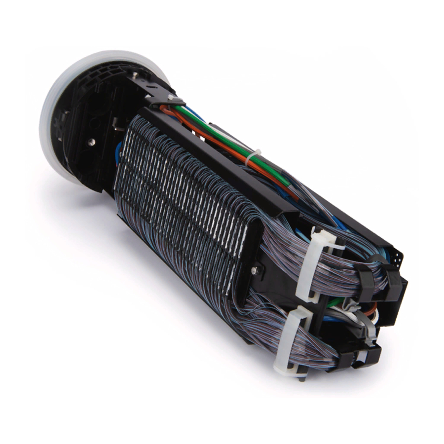
Figure 1
Advertisement
Table of Contents

Subscribe to Our Youtube Channel
Related Manuals for CORNING SCF-1296


Summary of Contents for CORNING SCF-1296
-
Page 1: Table Of Contents
SCF-1296/1728 Heat Shrink Open Ribbon System (HS-ORS) Canister Splice Closure P/N 206-455-AEN Issue 1 related literature | Search www.corning.com/opcomm. Click on “Resources/Standard Recommended Procedures.” TPA-6313 Figure 1 Table of Contents General ......................2 Tools and Materials . -
Page 2: General
General This instruction describes the recommended procedures for loading fiber optic cable into the SCF-1296/1728 Heat-Shrink Open Ribbon System (ORS) Canister Closure (Figure 1). Contact your customer service representative to purchase accessories that are sold separately. Tools and Materials The following tools and materials are required to complete this installation: •... - Page 3 One express (mid-span) cable may be placed in the express port or up to two individual cables may be installed using the supplied three-finger clip. Step 1: Place a wrap of tape around the cable sheath at the distance specified in Figure 2. Remove indicated length of cable sheath and armor (where applicable) according to cable manufacturer’s instructions.
-
Page 4: Prepare End Cap
Ribbon Cable for Drop Cable (non-mid-span) Prepare End Cap Step 1: Remove the frame from the end cap. Step 2: Open the appropriate cable port for your application based on the table in Figure 5. When using ports other than the oval port, use a taller port before using a shorter port. Oval ports line up best with central slack well. -
Page 5: Install Strain-Relief Hardware In Express Port
Install Strain-relief Hardware in Express Port Refer to SRP 206-288 (Heat-shrink End Cap Canister Closure Sealing Checklist) to ensure all critical steps for sealing the closure have been performed accurately. Step 1: Wrap a large hose clamp around the bracket and cable approximately 6 mm (0.25 inches) below the sheath opening (Figure 8). -
Page 6: Attach Frame To End Cap
Step 6: If more than one cable is being installed in the oval port, position the 3-finger clip between the two cables at the end of the heat-shrink tube (Figure 11). Step 7: Hold the cable while heating to prevent any movement. Step 8: Beginning at the port, gradually move a heat gun down the tube. -
Page 7: Load Express Fibers
Express cable Figure 13 TPA-6314 Load Express Fibers IMPORTANT: Basic ribbon fiber routing requires Ribbon “A” spliced to Ribbon “B.” Ribbon “B” will be routed to the side of the splice plane opposite from Ribbon “A.” • For sub-ribbon splicing, split the ribbon matrix with appropriate equipment (P/N RST-000 or equivalent) and separate ribbon matrix within 6 in of cable sheath opening. - Page 8 Peel the subunit to the mark exposing the ribbons. Step 4: Using the ribbon splitting tool (Corning P/N RST-000), split each 24-fiber ribbon into 12-fiber groups. Organize the ribbons in the desired splicing order. Secure the order with some non-aggressive tape, such as painter’s tape.
-
Page 9: Splice
Step 8: Open the plastic clip on the splice plane (“C”) and lay the fibers inside. Step 9: Carefully close the clip (Figure 18). Step 10: Lay the fibers all the way down the splice plane on the side of the organizer while maintaining a full loop of slack in the storage area. -
Page 10: Seal The Closure
IMPORTANT: Before cutting, make sure there is a complete loop of fibers in the side storage compartment and the fibers lie neatly in the trough of the splice plane. Step 2: Splice the fibers according to the appropriate instructions for the splicing equipment you are using. Step 3: Insert the protected splice (heat-shrink splice protectors are recommended) back into the first slot in the... -
Page 11: Install The Canister Cover
Step 2: Use the supplied brush to apply a third of the UCN lubricant to the sealing ring channel on the end cap (Figure 24). Step 3: Stretch the sealing ring over the channel. Step 4: Fold the edge of the seal that overlaps the outside of the end cap until the seal seats in the channel as shown in Figure 25. -
Page 12: Perform Flash Test
KPA-1723 KPA-1724 Figure 26 Perform Flash Test Step 1: Inject 12 to 14 psi (maximum) of air into the closure using a hand pump (Figure 27). Check pressure after each 25 pumps. WARNING: To avoid a potentially hazardous situation that could result in death or serious injury, do not exceed 14 psi (100 kpa) gauge pressure. - Page 13 APPENDIX A Drop Port Cables IMPORTANT: If the cable used is made with a metal central/strength member, use the grounding connector as for the armored cable, with the extension bracket to strain-relieve the central/strength member and ground it. Step 1: Remove nuts from the ground clamp.
- Page 14 800-743-2675 • FAX: 828-325-5060 • International: +1-828-901-5000 • www.corning.com/opcomm Corning Optical Communications reserves the right to improve, enhance, and modify the features and specifications of Corning Optical Communications products without prior notification. A complete listing of the trademarks of Corning Optical Communications is available at www.corning.com/opcomm/trademarks. All other trademarks are the properties of their respective owners.
Need help?
Do you have a question about the SCF-1296 and is the answer not in the manual?
Questions and answers