Table of Contents
Advertisement
Available languages
Available languages
Advertisement
Chapters
Table of Contents

Subscribe to Our Youtube Channel
Related Manuals for Atlantic 200L


Summary of Contents for Atlantic 200L
- Page 2 SCHÉMA ÉLECTRIQUE POUR LA MAINTENANCE DE VOTRE CHAUFFE-EAU THERMODYNAMIQUE ELECTRIC DIAGRAM SCHAKELSCHEMA VOOR DE SERVICEBEURT VAN UW THERMODYNAMISCHE WATERVERWARMER STROMLAUFPLAN FÜR DIE WARTUNG IHRES WARMWASSERBEREITERS MIT WÄRMEPUMPE SCHEMA ELETTRICO PER LA MANUTENZIONE DELLO SCALDACQUA TERMODINAMICO SCHEMAT POŁĄCZEŃ ELEKTRYCZNYCH PAŃSTWA TERMODYNAMICZNEGO PODGRZEWACZA WODY SCHEMA ELECTRIQUE SONDE AIR ELECTRIC DIAGRAM...
- Page 3 Manuel à conserver, même après l’installation du produit. AVERTISSEMENTS Cet appareil n’est pas prévu pour être utilisé par des personnes (y compris les enfants) dont les capacités physiques, sensorielles ou mentales sont réduites, ou des personnes dénuées d’expérience ou de connaissance, sauf si elles ont pu bénéficier, par l’intermédiaire d’une personne responsable de leur sécurité, d’une surveillance ou d’instructions préalables concernant l’utilisation de l’appareil.
- Page 4 AVERTISSEMENTS 3/ Si l’appareil doit être installé dans un local ou un emplacement dont la température ambiante est en permanence à plus de 35°C, prévoir une aération de ce local. 4/ Dans une salle de bain ne pas installer ce produit dans les volumes V0, V1 et V2. Si les dimensions ne le permettent pas, Ils peuvent néanmoins être installés dans Le volume V2.
- Page 5 AVERTISSEMENTS RACCORDEMENT ELECTRIQUE Avant tout démontage du capot, s’assurer que l’alimentation est coupée pour éviter tout risque de blessure ou d’électrocution. L’installation électrique doit comporter en amont de l’appareil un dispositif coupure omnipolaire (disjoncteur, fusible) conformément aux règles d’installation locales en vigueur (disjoncteur différentiel 30mA).
-
Page 6: Table Of Contents
Sommaire PRESENTATION 1. Recommandations importantes 2. Contenu de l’emballage 3. Manutention 4. Principe de fonctionnement 5. Caractéristiques techniques 6. Dimensions – structure 7. Nomenclature INSTALLATION 1. Mise en place du produit 2. Installation en configuration ambiant (sans gaine) 3. Installation en configuration gainée (2 conduits) 4. -
Page 7: Presentation
Présentation Installation Utilisation Entretien Garantie Présentation du produit 1. Recommandations importantes 1.1. Consignes de sécurité Les travaux d’installation et de service sur les chauffe-eau thermodynamiques peuvent présenter des dangers en raison de hautes pressions et de pièces sous tension électrique. Les chauffe-eau thermodynamiques doivent être installés, mis en service et entretenus par un personnel formé... -
Page 8: Manutention
Présentation Installation Utilisation Entretien Garantie 3. Manutention Le produit intègre plusieurs poignées afin de faciliter la manutention jusqu’au lieu d’installation. Pour transporter le chauffe-eau jusqu'au lieu d'installation utiliser les poignées inférieures et les poignées supérieures. Position acceptée Positions interdites Respecter les recommandations de transport et de manutention figurant sur l'emballage du chauffe- eau. -
Page 9: Caractéristiques Techniques
Présentation Installation Utilisation Entretien Garantie 5. Caractéristiques techniques Modèle 200L 200L C 270L 270L C Dimensions ( Hauteur x Largeur x Profondeur) 1617 x 620 x 665 1957 x 620 x 665 Poids à vide Capacité de la cuve Raccordement eau chaude / eau froide ¾... -
Page 10: Dimensions - Structure
Présentation Installation Utilisation Entretien Garantie 6. Dimensions / structure È Réf MODELE Sortie condensats 1166 1166 1525 1525 Hauteur totale 1617 1617 1957 1957 Entrée eau froide Sortie eau chaude 961 1300 1300 Largeur totale Profondeur totale 60° Entraxe bouches Entrée échangeur Dimensions en mm... -
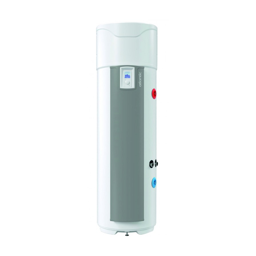
Page 11: Nomenclature
Présentation Installation Utilisation Entretien Garantie 7. Nomenclature Bouche orientable 11 Ensemble bornier 21 Colonne de façade Capot arrière 12 Capot avant 22 Bouchon bas de colonne Filtre 13 Compresseur 23 Filerie ACI Condensateur 15μF 14 Jaquette compresseur 24 Carte de régulation Détendeur 15 Couvercle jaquette 25 Filerie compresseur... -
Page 12: Installation
: située au-dessus de la sortie eau chaude doit être accessible à tout moment. 200L : 1750mm 270L : 2070mm Avant le remplissage, le chauffe-eau doit être mis de niveau en le calant si Fixer chauffe besoin. -
Page 13: Installation En Configuration Ambiant (Sans Gaine)
Présentation Installation Utilisation Entretien Garantie 2. Installation en configuration non gainée. Intérieur/Intérieur Local non chauffé à température supérieure à 5°C et isolé des pièces chauffées de l’habitation. Paramètre « Gainage » à mettre sur « Intérieur/Intérieur » Local conseillé = enterré ou semi enterré, pièce où la température est supérieure à... -
Page 14: Installation En Configuration Gainée (2 Conduits)
Présentation Installation Utilisation Entretien Garantie 3. Installation en configuration gainée (2 conduits). Extérieur/Extérieur Local au minimum hors gel (T > 1°C). Paramètre « Gainage » à mettre sur « Extérieur/Extérieur » Local conseillé : volume habitable (les déperditions thermiques du chauffe- eau ne sont pas perdues), à... -
Page 15: Installation En Configuration Semi-Gainée (1 Conduit Au Rejet)
Présentation Installation Utilisation Entretien Garantie 4. Installation en configuration semi – gainée (1 conduit au rejet). Local non chauffé à température supérieure à 5° C et isolé des pièces Intérieur/Extérieur chauffées de l’habitation. Paramètre « Gainage » à mettre sur « Intérieur/Extérieur ». Local conseillé... -
Page 16: Configurations Interdites
Présentation Installation Utilisation Entretien Garantie 5. Configurations interdites • Chauffe-eau puisant l’air d’une pièce chauffée. • Raccordement sur la VMC. • Raccordement sur les combles. • Gainage sur l’air extérieur à l’aspiration et refoulement de l’air frais à l’intérieur. • Raccordement à un puits canadien. •... -
Page 17: Raccordement Hydraulique
Présentation Installation Utilisation Entretien Garantie 6. Raccordement hydraulique L'usage d'un bouclage sanitaire est vivement déconseillé : une telle installation provoque une destratification de l'eau dans le ballon et a pour conséquence un fonctionnement plus important de la pompe à chaleur ainsi que de la résistance électrique L’entrée d’eau froide est repérée par une collerette bleue et la sortie d’eau chaude par une collerette rouge. - Page 18 Présentation Installation Utilisation Entretien Garantie 6.2. Raccordement eau chaude Ne pas raccorder directement aux canalisations en cuivre le raccord eau chaude. Il doit être obligatoirement équipé d’un raccord diélectrique (fourni avec l’appareil). En cas de corrosion des filetages du raccord eau chaude non équipé de cette protection, notre garantie ne pourrait être appliquée.
- Page 19 Présentation Installation Utilisation Entretien Garantie Qualité de l’eau Les caractéristiques de l’eau du circuit primaire utilisée dès la mise en service, et pour la durée de vie des chaudières seront conformes aux valeurs suivantes : • Lors du remplissage d’une installation neuve, ou lorsque celle-ci a été complètement vidangée, l’eau de remplissage doit être conforme aux caractéristiques suivantes : TH <...
- Page 20 Présentation Installation Utilisation Entretien Garantie 6.5. Evacuation des condensats Le refroidissement de l’air circulant au contact de l’évaporateur entraîne la condensation de l’eau contenue dans l’air. L’écoulement de l’eau condensée à l’arrière de la pompe à chaleur doit être conduit par des tuyaux en plastique depuis la pompe à chaleur afin d’évacuer les condensats. Selon l’humidité...
-
Page 21: Raccordement Aéraulique
Présentation Installation Utilisation Entretien Garantie 7. Raccordement aéraulique Lorsque le volume de la pièce où est installé votre chauffe-eau thermodynamique est inférieur à 20m , son raccordement à des gaines d’air de diamètre 160 mm est possible. Si les gaines d’air ne sont pas isolées, de la condensation peut apparaître sur celles-ci lors du fonctionnement. - Page 22 Présentation Installation Utilisation Entretien Garantie 7.1. Longueurs de gaines autorisées. Configurations types Gainage Extérieur/Extérieur Sorties / Entrées d’air Toiture Murale Toiture Murale Toiture Murale Gaine galva semi- rigide isolé Ø160mm 12 m 12 m 10 m Longueurs Max. Gaine PEHD Ø160mm L1 + L2 28 m 26 m...
-
Page 23: Raccordement Électrique
Présentation Installation Utilisation Entretien Garantie 8. Raccordement électrique Se référer au schéma de raccordement électrique situé en avant dernière page. Le chauffe-eau ne peut être mis sous tension qu’après son remplissage en eau. Le chauffe-eau doit être alimenté électriquement de façon permanente. Le chauffe-eau ne peut être branché... -
Page 24: Raccordement Des Équipements Optionnels
Présentation Installation Utilisation Entretien Garantie 9. Raccordement des équipements optionnels Avant toute intervention, veillez à mettre l’appareil hors tension. Pour accéder au bornier client, se reporter aux indications de démontage du capot avant Un passage de câble est spécifiquement prévu pour les raccordements. Veillez à l’utiliser. Il est préconisé... - Page 25 Présentation Installation Utilisation Entretien Garantie Onduleur Panneaux PV MP POWER Boitier de Signal 230V~ - 50Hz raccordement 3G 2,5mm² 3G 1,5mm² 2x 0,75mm² 9.2. Raccordement à une chaudière. Alimentation électrique Pour les appareils équipés d’un échangeur interne qui seront couplés à une chaudière, il est nécessaire de connecter la chaudière au chauffe-eau.
- Page 26 Présentation Installation Utilisation Entretien Garantie 9.3. Raccordement à une station solaire. Il est possible de connecter une station solaire thermique au Alimentation électrique chauffe eau (appareil avec échangeurs en mode « solaire»). Dans cette configuration, le chauffe-eau fonctionne uniquement lorsqu'il reçoit un signal de la station solaire. A réception du signal, la PAC démarrera s'il y a un besoin de chauffe et que les plages de fonctionnement et d'air le permettent.
-
Page 27: Mise En Service
Présentation Installation Utilisation Entretien Garantie 10. Mise en service 10.1. Remplissage du chauffe-eau ❶ Ouvrir le ou les robinets d’eau chaude. ❷ Ouvrir le robinet d’eau froide situé sur le groupe de sécurité (s’assurer que le clapet de vidange du groupe est en position fermée). - Page 28 Présentation Installation Utilisation Entretien Garantie 10.3. Les réglages de l’installation. Accéder à nouveau aux différents réglages de l’installation : Paramétrages • Date et heure Régler le jour puis valider. Procéder de la même façon pour le mois, l’année, l’heure et les minutes. Valider ou non le changement d’heure automatique •...
- Page 29 Présentation Installation Utilisation Entretien Garantie • Photovoltaïque/Smart-grid : Ce paramètre permet d’activer le couplage du produit avec une installation photovoltaïque. Ce mode de fonctionnement se traduit par la mise en marche forcée de la pompe à chaleur lorsqu’un signal, provenant de l’installation photovoltaïque, est reçu par le chauffe-eau.
- Page 30 Présentation Installation Utilisation Entretien Garantie 10.6. Choix du mode de fonctionnement Mode L’appui sur la touche permet d’accéder au menu En mode AUTO : Ce mode de fonctionnement gère de façon automatique le choix de l’énergie qui permet de faire le meilleur compromis entre confort et économies.
-
Page 31: Utilisation
Présentation Installation Utilisation Entretien Garantie Utilisation 1. Panneau de commandes. Visualiser les informations Suivre les instructions Accéder aux réglages MENU Verrouiller les réglages Naviguer Diminuer/Augmenter les valeurs Valider Revenir à l’écran précédent 2. Description des pictogrammes. Appoint électrique en cours de Marche forcée enregistrée fonctionnement Pompe à... -
Page 32: Le Menu Principal
Présentation Installation Utilisation Entretien Garantie 3. Le menu principal. Naviguer dans le MENU Accéder aux Suivre les instructions Diminuer Augmenter Valider réglages affichées à l’écran les valeurs les valeurs Augmenter la production d’eau chaude ponctuellement : Régler le nombre de jours de fonctionnement du BOOST (de 1 à 7). A la fin de la durée choisie, le chauffe-eau reprend son fonctionnement initial. -
Page 33: Les Modes De Fonctionnement
Présentation Installation Utilisation Entretien Garantie 4. Les modes de fonctionnement. 4.1 Les modes en installation « Thermodynamique seul » : AUTO: La température de consigne est automatiquement ajustée entre 50 et 62°C selon le profil de consommation des jours précédents. Le chauffe eau choisit de préférence la pompe à chaleur pour fonctionner. -
Page 34: Entretien
Présentation Installation Utilisation Entretien Garantie Entretien, Maintenance et Dépannage 1. Conseils à l’utilisateur. Une vidange du chauffe-eau est nécessaire dans le cas où le mode absence ne peut être utilisé ou dès lors que l’appareil est mis hors tension. Procéder de la façon suivante : ❶... -
Page 35: Ouverture Du Produit Pour Maintenance
Présentation Installation Utilisation Entretien Garantie L’accès à la vis de réglage du détendeur par un personnel non frigoriste est interdit. Tout réglage du détendeur sans avis favorable du constructeur peut conduire à une non prise sous garantie du produit. Il est déconseillé de toucher au réglage du détendeur avant d’avoir épuisé toutes les autres solutions de réparation. -
Page 36: Diagnostique De Panne
Présentation Installation Utilisation Entretien Garantie 4. Diagnostic de panne. En cas d’anomalie, absence de chauffe ou dégagement de vapeur au soutirage, coupez l’alimentation électrique et prévenez votre installateur. Les opérations de dépannage doivent être réalisées exclusivement par un professionnel. 4.1. Affichage de codes d’erreur. L'alarme peut être suspendue ou réarmée en appuyant sur OK. - Page 37 Présentation Installation Utilisation Entretien Garantie Code affiché Cause Conséquence Dépannage Vérifier les connexions du compresseur (repère R1), Ouverture du pressostat, du condensateur de démarrage pressostat ou Arrêt PAC. Erreur 25 (15mF) et de la vanne gaz chauds (Repère T2). sécurité thermique Chauffe en ELEC.
- Page 38 Présentation Installation Utilisation Entretien Garantie Panne constatée Cause possible Diagnostic et dépannage Plus de chauffe Pas d’alimentation électrique du Vérifier la présence de tension Pas d’eau chaude chauffe eau : fusible, câblage… sur les fils d’alimentation Vérifier les paramètres de l’installation (voir les plages de fonctionnement) Quantité...
-
Page 39: Garantie
Présentation Installation Utilisation Entretien Garantie Garantie 1. Champs d’application de la garantie. Sont exclues de cette garantie les défaillances dues à : • Des conditions d’environnement anormales : • Dégâts divers provoqués par des chocs ou des chutes au cours des manipulations après départ usine. -
Page 40: Conditions De Garantie
Présentation Installation Utilisation Entretien Garantie 2. Conditions de garantie. Le chauffe-eau doit être installé par une personne habilitée conformément aux règles de l’art, aux normes en vigueur et aux prescriptions de nos services techniques. Il sera utilisé normalement et régulièrement entretenu par un spécialiste. Dans ces conditions, notre garantie s’exerce par échange ou fourniture gratuite à... -
Page 41: Déclaration De Conformité
Présentation Installation Utilisation Entretien Garantie 3. Déclaration de conformité. DECLARATION DE CONFORMITE DIRECTIVE RED 2014/53/UE (*) Par la présente SATE déclare que l'équipement référencé ci-dessous est conforme aux exigences essentielles de la directive RED 2014/53/UE. La déclaration de conformité UE complète de cet équipement est aussi disponible sur demande, auprès de notre service après-vente (voir adresse et coordonnées en fin de notice). - Page 43 Keep the manual, even after the product has been installed. WARNINGS This product is not intended for use by persons (including children) whose physical, sensory or mental capacities are reduced, or persons without experience or knowledge, unless they have been given instructions & monitored previously when using the appliance by a person responsible for their safety.
- Page 44 WARNINGS 3/ If the appliance is to be installed in a room or location where the ambient temperature is permanently above 35°C, provide ventilation in the room. 5/ Do not use volumes V0, V1 or V2 if installing this product in a bathroom. Volume V2 can, however, be used if the dimensions cannot accommodate another size.
- Page 45 WARNINGS ELECTRICAL CONNECTION Before taking off the cover, make sure that the power is turned off to prevent injury or electric shock. The electrical installation must include an omnipolar cut-off device (circuit-breaker, fuse) upstream of the appliance, complying with local installation rules in force (30mA differential circuit breaker).
- Page 46 Contents OVERVIEW 1. Important recommendations 2. Content of the packaging 3. Handling 4. Operating principle 5. Technical characteristics 6. Dimensions – structure 7. Glossary INSTALLATION 1. Positioning the product 2. Installation in ambient configuration (without ducting) 3. Installation in ducted configuration (2 ducts) 4.
-
Page 47: Overview
Overview Installation Maintenance Warranty Product overview 1. Important recommendations 1.1. Safety instructions Installation and service work on thermodynamic water heaters can be hazardous due to high pressures and live parts. Thermodynamic water heaters must be installed, commissioned and maintained by trained and qualified personnel only. -
Page 48: Handling
Overview Installation Maintenance Warranty 3. Handling The product incorporates several handles making it easier to move to the location where it will be installed. To transport the water heater to the installation location use the lower and upper handles. Acceptable position Prohibited positions Follow the transport and handling recommendations on the water heater's packaging. -
Page 49: Technical Characteristics
Overview Installation Maintenance Warranty 5. Technical characteristics Model 200L 200L C 270L 270L C Dimensions (Height x Width x Depth) 1617 x 620 x 665 1957 x 620 x 665 Weight empty Tank capacity Hot water/cold water connection ¾ ʺ M... -
Page 50: Dimensions/Structure
Overview Installation Maintenance Warranty 6. Dimensions/structure È MODEL COIL COIL Condensate outlet 1166 1166 1525 1525 Total height 1617 1617 1957 1957 Cold water inlet Hot water outlet 961 1300 1300 Total width Total depth 60° Inlet dimensions Exchanger inlet Dimensions in mm... -
Page 51: Glossary
Overview Installation Maintenance Warranty 7. Glossary Directional inlet 11 Terminal assembly 21 Front column Rear cover 12 Front cover 22 Lower column cap Filtered 13 Compressor 23 ACI wiring Capacitor 15μF 14 Compressor jacket 24 Regulation board Expansion valve 15 Jacket cover 25 Compressor wiring Hot gases valve assembly 16 Column rail mounting... -
Page 52: Installation
Minimum height needed from floor to The identification label ceiling to install the product: located above the hot water outlet must be accessible at all times. 200L: 1750mm 270L: 2070mm Before filling, the water heater must be levelled wedging Attach the water necessary. -
Page 53: Installation In Ambient Configuration (Without Ducting)
Overview Installation Maintenance Warranty 2. Installation in a non-ducted configuration. Interior/Interior Unheated location at temperatures above 5°C and isolated from the heated rooms of the house. "Ducting" setting to be set to "Interior/Interior" Recommended location = underground or semi-underground, room where the temperature is higher than 10°C all year round. -
Page 54: Installation In Ducted Configuration (2 Ducts)
Overview Installation Maintenance Warranty 3. Installation in ducted configuration (2 ducts). Exterior/Exterior Location is at least frost-free (T > 1°C). "Ducting" setting to be set to "Exterior/Exterior" Recommended location: living space (the thermal losses of the water heater are not lost), near the outer walls. Avoid placing the water heater and/or the ducts close to bedrooms for sound comfort. -
Page 55: Installation In Semi-Ducted Configuration (1 Discharge Duct)
Overview Installation Maintenance Warranty 4. Installation in semi–ducted configuration (1 discharge duct). Unheated location at temperatures above 5°C and isolated from the Interior/Exterior heated rooms of the house. "Ducting" setting to be set to "Interior/Exterior" Recommended location = underground or semi-underground, room where the temperature is higher than 10°C all year round. -
Page 56: Prohibited Configurations
Overview Installation Maintenance Warranty 5. Prohibited configurations • Water heater drawing air from a heated room. • Connection to the CMV. • Connection to the attic. • Ducting for suction of outside air and discharge of fresh air inside. • Connection to a Canadian well. •... -
Page 57: Hydraulic Connection
Overview Installation Maintenance Warranty 6. Hydraulic connection The use of a sanitary loop is strongly discouraged: this type of installation causes a destratification of the water in the heater and results in the increased operation of the heat pump as well as the electrical resistance The cold water inlet is marked by a blue collar and the hot water outlet by a red collar. - Page 58 Overview Installation Maintenance Warranty 6.2. Hot water connection Do not connect the hot water connection directly to the copper pipes. It must be equipped with a dielectric connection (supplied with the appliance). In case of corrosion of the threads of the hot water connection not equipped with this protection, our warranty will not apply.
- Page 59 Overview Installation Maintenance Warranty Water quality The characteristics of the primary circuit water used from the time of commissioning, and for the working life of the boilers, will conform to the following values: • When filling a new installation, or when an installation has been completely emptied, the water used for filling should conform to the following values: TH <...
- Page 60 Overview Installation Maintenance Warranty 6.5. Condensate removal The circulating air cools in contact with the evaporator and causes the water contained in the air to condensate. The flow of condensed water at the back of the heat pump must be carried away from the heat pump by plastic pipes in order to drain the condensates.
-
Page 61: Air Duct Connection
Overview Installation Maintenance Warranty 7. Air duct connection When the volume of the room where your thermodynamic water heater is installed is less than 20m , it can be connected to air ducts with a diameter of 160mm. If the air ducts are not insulated, condensation may appear on them during operation. - Page 62 Overview Installation Maintenance Warranty 7.1. Lengths of permitted ducts. Standard configurations Exterior/Exterior ducting Air Outlets/Inlets Roof Wall Roof Wall Roof Wall Semi-rigid galvanised duct Ø160mm 12 m 12 m 10 m Lengths Max. HDPE duct Ø 160 mm L1 + L2 28 m 26 m 16 m...
-
Page 63: Electrical Connection
Overview Installation Maintenance Warranty 8. Electrical connection Refer to the electrical wiring diagram on the next to last page. The water heater can only be turned on after it has been filled with water. The water heater must be permanently powered by electricity. The water heater can only be connected and operated on a single-phase 230V AC grid. -
Page 64: Connection Of Optional Equipment
Overview Installation Maintenance Warranty 9. Connection of optional equipment Before any operation, make sure to turn the appliance off. Refer to the disassembly instructions on the front cover for accessing the customer's terminal block. A cable bushing is specifically provided for connections. Be sure to use it. The use of a 2x0.5mm²... - Page 65 Overview Installation Maintenance Warranty Inverter PV panels MP POWER AC connection Signal 230V~ - 50Hz 3G 25mm² 3G 15mm² 2x 075mm² 9.2. Boiler connection Power supply For appliances equipped with an internal heat exchanger that will be coupled to a boiler, the boiler must be connected to the water heater.
- Page 66 Overview Installation Maintenance Warranty 9.3. Connection to a solar station. A solar heating station can be connected to the water heater Power supply (unit with heat exchangers in "solar" mode). In this configuration, the water heater only operates when it receives a signal from the solar station.
-
Page 67: Start-Up
Overview Installation Maintenance Warranty 10. Start-up 10.1. Filling the water heater ❶ Open the hot water taps. ❷ Open the cold water tap on the safety unit (make sure that the unit drain valve is in the closed position). Close the hot water taps after filling is completed. The water heater is now full of water. ❸... - Page 68 Overview Installation Maintenance Warranty 10.3. Installation settings. Re-access the installation's different settings: Settings • Date and time Set the day and confirm. Proceed in the same way for the month, the year, the hour and the minutes. Validate or not the automatic time change •...
- Page 69 Overview Installation Maintenance Warranty • Photovoltaic/Smart-grid: This setting allows you to activate the connection of the product with a photovoltaic system. The operation results in the forced start of the heat pump when a signal from the photovoltaic system is received by the water heater.
- Page 70 Overview Installation Maintenance Warranty 10.6. Choice of operating mode Mode Pressing the key accesses the menu In AUTO mode: This operating mode automatically manages the choice of energy that ensures the best compromise between comfort and savings. The water heater analyses the consumptions from the previous days to adapt hot water production to the actual needs.
-
Page 71: Use
Overview Installation Maintenance Warranty 1. Control panel. Review the information Follow the instructions Access the settings MENU Lock the settings Navigate Decrease/Increase the values Validate Return to the previous screen 2. Description of pictograms. Electrical backup currently Recorded forced operation operating Heat pump currently operating Recorded/ongoing absence... -
Page 72: The Main Menu
Overview Installation Maintenance Warranty 3. The main menu. Navigate the MENU Access the Follow the instructions on Decrease Increase Validate settings the screen the values the values Occasionally increase the production of hot water: Set the number of days of BOOST operation (from 1 to 7). The water heater resumes its initial operation at the end of the selected time period. -
Page 73: Operating Modes
Overview Installation Maintenance Warranty 4. Operating modes. 4.1 Modes in "Thermodynamics only" installation: AUTO: The setpoint temperature is thus automatically adjusted between 50 and 62° C depending on the consumption history. The water heater preferentially selects the heat pump to operate. The electrical backup can be activated automatically in support. -
Page 74: Maintenance
Overview Installation Maintenance Warranty Servicing, Maintenance and Troubleshooting 1. Tips for the user. The water heater ishould be drained if the absence mode cannot be used or when the appliance is switched off. Proceed as follows: ❶ Cut the power supply. ❷... -
Page 75: Maintenance
Overview Installation Maintenance Warranty Access to the regulator adjusting screw by non-refrigeration personnel is prohibited. Any adjustment of the regulator without approval from the manufacturer may lead to voiding of the warranty for this product. It is not recommended to touch the regulator setting until you have exhausted all other repair solutions. -
Page 76: Troubleshooting
Overview Installation Maintenance Warranty 4. Fault diagnostic. In the event of a fault, or when no heat or steam is issued from the filling point, switch off the power supply and inform your installer. Troubleshooting operations must be carried out exclusively by a professional. 4.1. - Page 77 Overview Installation Maintenance Warranty Code displayed Cause Consequence Troubleshooting Check the connections of the compressor (mark Pressure switch HP stopped. R1), the pressure switch, the start capacitor (15mF) Error 25 opening or thermal Heating in ELEC. and the hot gas valve (Mark T2). Check the compressor safety resistances of the compressor coils.
- Page 78 Overview Installation Maintenance Warranty Fault observed Possible cause Diagnostics and troubleshooting No more heat No power supply to the water Check the presence of voltage on No hot water heater: fuse, wiring ... the power cables Check the installation settings (see the operating ranges) Not enough hot water Hot water heater not large enough...
-
Page 79: Warranty
Overview Installation Maintenance Warranty Warranty 1. Scope of the warranty. This warranty does not cover failures due to: • Abnormal environmental conditions: • All types of damage caused by shaking or the appliance falling during handling after leaving the factory. •... -
Page 80: Warranty Conditions
Overview Installation Maintenance Warranty 2. Warranty conditions. The water heater must be installed by an authorised person in accordance with industry practices, the standards in force and the instructions from our technical services. It must be used normally and regularly serviced by a specialist. Under these conditions, our warranty is exercised by exchange or free supply to our Distributor or Installer of the parts deemed defective by our technicians, or if necessary of the appliance, excluding labour or transportation costs and any extended warranty. -
Page 81: Certificate Of Conformity
Overview Installation Maintenance Warranty 3. Certificate of conformity. DECLARATION OF CONFORMITY DIRECTIVE RED 2014/53/EU (*) SATE hereby declares that the equipment referenced below complies with the essential requirements of the RED 2014/53/EU Directive. The complete EU declaration of conformity concerning this equipment is also available on request from our after-sales service (see address and contact details at the end of the instructions). - Page 83 Bewaar deze handleiding, zelfs na de installatie van het product. WAARSCHUWINGEN Dit apparaat is niet bedoeld om te worden gebruikt door personen (kinderen inbegrepen) met fysieke, sensoriële of mentale beperkingen, of door personen met onvoldoende ervaring of kennis, tenzij ze kunnen genieten, door de tussenkomst van een persoon, verantwoordelijk voor hun veiligheid, van bewaking of voorafgaandelijke instructies betreffende het gebruik van het apparaat.
- Page 84 WAARSCHUWINGEN 4/ In een badkamer dit product niet installeren in de volumes V0, V1 en V2. Als de afmetingen geen andere mogelijkheid bieden, kan het product Echter in volume V2 geïnstalleerd worden. 5/ Het apparaat in een toegankelijke ruimte plaatsen. 6/ De afbeeldingen voor installatie raadplegen in het hoofdstuk “Installatie”.
- Page 85 WAARSCHUWINGEN De werkdruk van het circuit van de warmtewisselaar mag niet meer dan 0,3 MPa (3 bar) bedragen en de temperatuur hiervan mag niet meer dan 85°C zijn. ELEKTRISCHE AANSLUITING Alvorens het deksel te demonteren, controleren of de stroomvoorziening onderbroken is, om ieder risico op letsel of elektrocutie te vermijden.
- Page 86 Inhoudsopgave PRESENTATIE 1. Belangrijke instructies 2. Inhoud van de verpakking 3. Behandeling 4. Werkingsprincipe 5. Technische kenmerken 6. Afmetingen – structuur 7. Benaming INSTALLATIE 1. Plaatsing van het product 2. Installatie in de omgevingsconfiguratie (zonder mantel) 3. Installatie in de configuratie met mantel (2 leidingen). 4.
-
Page 87: Presentatie
Presentatie Installatie Gebruik Onderhoud Garantie Presentatie van het product 1. Belangrijke instructies 1.1. Veiligheidsvoorschriften De installatie- en onderhoudswerkzaamheden aan de thermodynamische waterverwarmers kunnen gevaarlijk zijn als gevolg van de hoge druk en de onder elektrische spanning staande onderdelen. De thermodynamische waterverwarmers mogen uitsluitend geïnstalleerd, in dienst gesteld en onderhouden worden door hiervoor opgeleid en gekwalificeerd personeel. -
Page 88: Behandeling
Presentatie Installatie Gebruik Onderhoud Garantie 3. Behandeling Het product is voorzien van een aantal handgrepen hanteren vergemakkelijken op de installatieplaats. Om de ketel te verplaatsen naar de plaats van installatie, de onderste en bovenste handgrepen gebruiken. Toegestane positie Verboden posities Respecteer de aanbevelingen voor transport en behandeling op de verpakking van de waterverwarmer. -
Page 89: Technische Kenmerken
Presentatie Installatie Gebruik Onderhoud Garantie 5. Technische kenmerken Model 200L 200L C 270L 270L C Afmetingen (hoogte x breedte x diepte) 1617 x 620 x 665 1957 x 620 x 665 Leeg gewicht Inhoud van de kuip Aansluiting warm water / koud water ¾... -
Page 90: Afmetingen - Structuur
Presentatie Installatie Gebruik Onderhoud Garantie 6. Afmetingen / structuur È 200. 270. MODEL Uitlaat condenswater 1166 1166 1525 1525 Totale hoogte 1617 1617 1957 1957 Inlaat koud water Uitlaat warm water 1300 1300 Totale breedte Totale diepte Tussenruimte 60° monden Inlaat warmtewisselaar Afmetingen in mm... -
Page 91: Benaming
Presentatie Installatie Gebruik Onderhoud Garantie 7. Benaming Richtbare mond 11 Klemmenbord compleet 21 Kolom voorpaneel Achterkap 12 Voorkap 22 Deksel onderzijde kolom Filter 13 Compressor 23 ACI-bedrading Condensator 15μF 14 Mantel compressor 24 Regelkaart Ontspanner 15 Deksel mantel 25 Compressorbedrading Klep hete gassen compleet 16 Rail ondersteuning kolom Bedrading 1 sensor waterreservoir... -
Page 92: Installatie
Minimum hoogte van vloer tot plafond Het typeplaatje boven die nodig is om te voldoen aan het de warmwateruitgang product: moet te allen tijde toegankelijk zijn. 200L: 1750mm 270L: 2070mm Voorafgaand aan het vullen, moet de waterverwarmer Zet de waterpas worden gezet,... -
Page 93: Installatie In De Omgevingsconfiguratie (Zonder Mantel)
Presentatie Installatie Gebruik Onderhoud Garantie 2. Installatie met configuratie zonder mantel. Binnen/Binnen Onverwarmde ruimte bij temperatuur boven de 5°C en geïsoleerd van de verwarmde vertrekken van de woning. Parameter "Mantel" instellen op "Intern/Intern" Aanbevolen ruimte = ingegraven of half ingegraven, waar de temperatuur boven de 10ºC is gedurende het hele jaar. -
Page 94: Installatie In De Configuratie Met Mantel (2 Leidingen)
Presentatie Installatie Gebruik Onderhoud Garantie 3. Installatie in de configuratie met mantel (2 leidingen). Lokaal minimaal vorstvrij (T > 1°C). Buiten/Buiten Parameter "Mantel" op "Extern/Extern" Aanbevolen ruimte: bewoonbaar volume (warmteverlies van de waterverwarmer gaat niet verloren), in de buurt van buitenmuren. Vermijd de nabijheid bij slaapkamers voor de waterverwarmer de boiler en/of leidingen vanwege geluidshinder. -
Page 95: Installatie In De Configuratie Met Halve Mantel (1 Leiding Naar Afvoer)
Presentatie Installatie Gebruik Onderhoud Garantie 4. Installatieconfiguratie met halve mantel (1 leiding naar afvoer). Onverwarmde ruimte bij temperatuur boven de 5°C en geïsoleerd van Binnen/Buiten verwarmde delen in de ruimte. Parameter "Mantel" op "Intern/Extern" zetten. Aanbevolen ruimte = ingegraven of half ingegraven, waar de temperatuur boven de 10ºC is gedurende het hele jaar. -
Page 96: Verboden Configuraties
Presentatie Installatie Gebruik Onderhoud Garantie 5. Verboden configuraties • Waterverwarmers die lucht aanzuigen uit een verwarmde ruimte. • Aansluiting op de mechanische ventilatie. • Aansluiting op de ruimte onder het dak. • Mantel op de buitenlucht bij de aanzuiging en uitblazen van koele lucht binnen. •... -
Page 97: Hydraulische Aansluiting
Presentatie Installatie Gebruik Onderhoud Garantie 6. Hydraulische aansluiting Het gebruik van een sanitair circuit wordt ten stelligste afgeraden: een dergelijke installatie veroorzaakt destratificatie van het water in de boiler en zorgt dat de warmtepomp en de elektrische weerstand harder moeten werken De koudwaterinlaat wordt aangegeven met een blauwe kraag en de warmwateruitlaat met een rode kraag. - Page 98 Presentatie Installatie Gebruik Onderhoud Garantie 6.2. Aansluiting warm water De aansluiting voor warm water niet rechtstreeks aansluiten op koperen leidingen. Deze moet verplicht worden voorzien van een diëlektrische aansluiting (meegeleverd met het apparaat). In geval van corrosie van de schroefdraden van aansluitingen voor warm water die niet uitgerust zijn met deze beveiliging is onze garantie niet geldig.
- Page 99 Presentatie Installatie Gebruik Onderhoud Garantie Kwaliteit van het water De karakteristieken van het primaire circuitwater dat wordt gebruikt vanaf het opstarten en gedurende de levensduur van de ketels moeten voldoen aan de volgende waarden: • Bij het vullen van een nieuwe installatie of wanneer deze volledig leeg is, moet het vulwater aan de volgende kenmerken voldoen: TH <...
- Page 100 Presentatie Installatie Gebruik Onderhoud Garantie 6.5. Condensafvoer Door het afkoelen van de lucht die bij contact met de verdamper circuleert, condenseert het in de lucht aanwezige vocht. Het wegstromen van het gecondenseerde water aan de achterkant van de pomp moet geleid worden door plastic leidingen vanaf de warmtepomp om de condens af te voeren.
-
Page 101: Aansluiting Ventilatie
Presentatie Installatie Gebruik Onderhoud Garantie 7. Aansluiting ventilatie Wanneer het volume van het vertrek waar uw thermodynamische waterverwarmer geïnstalleerd is, minder dan 20 m is, kan deze aangesloten worden op luchtmantels met een diameter van 160 mm. Als de luchtmantels niet geïsoleerd zijn, kan hier tijdens de werking condens op verschijnen. U moet derhalve altijd voor geïsoleerde luchtmantels kiezen. - Page 102 Presentatie Installatie Gebruik Onderhoud Garantie 7.1. Toegestane mantellengtes. Standaard configuraties Mantels Buiten/Buiten Luchtuitlaten / -inlaten Muur Muur Muur Half stijve verzinkte geïsoleerde mantel Ø 12 m 12 m 10 m 160 mm Max. lengtes Mantel PEHD Ø 160 L1 + L2 28 m 26 m 16 m...
-
Page 103: Elektrische Aansluiting
Presentatie Installatie Gebruik Onderhoud Garantie 8. Elektrische aansluiting Raadpleeg het elektrische bedradingsschema dat zich tegenover de laatste pagina bevindt. De waterverwarmer mag pas na met water gevuld te zijn ingeschakeld worden. De waterverwarmer moet permanent van stroom voorzien worden. De waterverwarmer mag enkel aangesloten worden en werken op een eenfasig wisselstroomnet 230V. De waterverwarmer aansluiten met een stijve kabel met geleiders met een doorsnede van 1,5 mm². -
Page 104: Aansluiten Van Optionele Uitrustingen
Presentatie Installatie Gebruik Onderhoud Garantie 9. Aansluiten van optionele uitrustingen Alvorens werkzaamheden uit te voeren, het apparaat uitschakelen. Zie voor de toegang tot het klemmenbord voor de klant de aanwijzingen voor het demonteren van de voorkap Er is een speciale kabeldoorvoer voor de aansluitingen. Zorg dat deze gebruikt wordt. Het is aan te raden een meerdradige kabel 2x0,5mm²... - Page 105 Presentatie Installatie Gebruik Onderhoud Garantie Ondulator PV-panelen MP POWER Aansluitingska Signaal 230V~ - 50Hz stje AC 3G 2,5mm² 3G 1,5mm² 2x 0,75mm² 9.2. Aansluiting op een ketel. Voor de apparaten uitgerust met een interne warmtewisselaar die aan een ketel gekoppeld zullen worden, moet de ketel Stroomvoorziening worden aangesloten op de waterverwarmer.
- Page 106 Presentatie Installatie Gebruik Onderhoud Garantie 9.3. Aansluiting op een zonnestation. mogelijk thermisch zonnestation Stroomvoorziening waterverwarmer aan te sluiten (apparaat met warmtewisselaars in de “zonne”-modus). In deze configuratie werkt de waterverwarmer enkel wanneer deze een signaal van het zonnestation ontvangt. Na het signaal ontvangen te hebben, start de warmtepomp als er behoefte aan verwarming is en als het Zonne-aansluiting werkings- en luchtbereik dit toestaan.
-
Page 107: Indienststelling
Presentatie Installatie Gebruik Onderhoud Garantie 10. Indienststelling 10.1. Het vullen van de waterverwarmer ❶ Open de warmwaterkra(a)n(en). ❷ Open de koudwaterkraan op de veiligheidsgroep (controleer of de aftapklep van de groep in de gesloten stand staat). ❸ Sluit de warmwaterkranen zodra hier water uit begint te stromen. De waterverwarmer zit vol met water. ❹... - Page 108 Presentatie Installatie Gebruik Onderhoud Garantie 10.3. De instellingen van de installatie. Opnieuw de verschillende instellingen van de installatie aanpassen: Parametreringen • Datum en tijd Stel de dag in en bevestig. Ga op dezelfde manier te werk voor de maand, het jaar, de uren en de minuten. Valideer al dan niet de automatische verandering van zomer- in wintertijd en omgekeerd •...
- Page 109 Presentatie Installatie Gebruik Onderhoud Garantie • Fotovoltaïsch / Smart-Grid: Deze instelling laat toe de koppeling van het product met een fotovoltaïsche installatie te activeren. Deze werkingsmodus leidt tot de geforceerde inschakeling van de warmtepomp als een signaal van de fotovoltaïsche installatie wordt ontvangen door de waterverwarmer. De regeling keert automatisch terug naar de eerder gekozen modus na het ontbreken van het signaal van het fotovoltaïsche station.
- Page 110 Presentatie Installatie Gebruik Onderhoud Garantie 10.6. Keuze van de werkingsmodus Modus Een druk op de toets geeft toegang tot het menu In de modus AUTO: Deze werkingsmodus beheert automatisch de energiekeuzes die het beste compromis geven tussen comfort en energiebesparing. Het toestel analyseert het verbruik van de vorige dagen om de productie van warm water aan te passen aan de behoeften.
-
Page 111: Gebruik
Presentatie Installatie Gebruik Onderhoud Garantie Gebruik 1. Bedieningspaneel. Weergeven informatie Volg de instructies Toegang tot instellingen MENU Vergrendelen instellingen Navigeren Verhogen / verlagen waarden Bevestigen Keer terug naar het vorige scherm 2. Beschrijving van de pictogrammen. Extra elektrische warmtetoevoer Geforceerde werking geregistreerd tijdens werking Warmtepomp in werking Geen geregistreerde werking /... -
Page 112: Het Hoofdmenu
Presentatie Installatie Gebruik Onderhoud Garantie 3. Het hoofdmenu. Navigeren door het menu Toegang tot Volg de instructies op het De waarden De waarden Bevestigen instellingen scherm verlagen verhogen Verhogen van de warmwaterbereiding op specifieke momenten: Instellen van het aantal dagen van de werking van de BOOST (1 tot 7). Na afloop van de gekozen tijd herneemt de verwarming opnieuw de oorspronkelijke werking. -
Page 113: De Werkingsmodi
Presentatie Installatie Gebruik Onderhoud Garantie 4. De werkingsmodi. 4.1 De installatiemodi "Enkel thermodynamisch": AUTO: De ingestelde temperatuur wordt automatisch aangepast tussen de 50 en 62ºC, afhankelijk van het verbruiksprofiel van de voorgaande dagen. De waterverwarmer wordt bij voorkeur gekozen gecombineerd met de warmtepomp voor de werking. -
Page 114: Onderhoud
Presentatie Installatie Gebruik Onderhoud Garantie Onderhouden reparatie 1. Adviezen aan de gebruiker. Het aftappen van de waterverwarmer is nodig in het geval dat de functie afwezigheid niet kan worden gebruikt of wanneer het apparaat wordt uitgeschakeld. Ga als volgt te werk: ❶... -
Page 115: Het Product Openen Voor Onderhoud
Presentatie Installatie Gebruik Onderhoud Garantie De toegang tot de afstelschroef van de ontspanner is verboden voor monteurs die geen koelspecialist zijn. Bij een afstelling van de ontspanner zonder voorafgaande toestemming door de fabrikant kan de garantie van het product geannuleerd worden. Het is af te raden aan de instelling van de ontspanner te komen voor u alle andere reparatieoplossingen geprobeerd heeft. -
Page 116: Diagnose In Geval Van Problemen
Presentatie Installatie Gebruik Onderhoud Garantie 4. Storingsdiagnose. In geval van een storing, gebrek aan verwarming of het vrijkomen van stoom bij onderdruk, schakel de elektrische voeding uit en waarschuw uw installateur. Werkzaamheden in verband met het verhelpen van storingen mogen alleen worden uitgevoerd do een vakman. - Page 117 Presentatie Installatie Gebruik Onderhoud Garantie Weergegeven code Oorzaak Gevolg Storingen verhelpen De aansluitingen van de compressor (nummer R1), van Opening pressostaat de pressostaat, van de startcondensator (15mF) en van of thermische Uitschakeling WP. Fout 25 de klep voor hete gassen (nummer T2) verifiëren. De beveiliging ELEK verwarming weerstanden van de spoelen van de compressor...
- Page 118 Presentatie Installatie Gebruik Onderhoud Garantie Geconstateerde storing Mogelijke oorzaak Diagnose en verhelping storing Geen verwarming meer Geen stroomvoorziening voor de Verifiëren of er spanning op de Geen warm water waterverwarmer: zekering, voedingsdraden staat bekabeling... De parameters van de installatie verifiëren (zie de werkingsgebieden) Onvoldoende hoeveelheid warm water Te kleine waterverwarmer De tijdsduur van de...
-
Page 119: Garantie
Presentatie Installatie Gebruik Onderhoud Garantie Garantie 1. Toepassingsgebied van de garantie. Deze garantie geldt niet voor defecten als gevolg van: • Abnormale omgevingsvoorwaarden: • Schade als gevolg van schokken of valpartijen tijdens hantering na het vertrek uit de fabriek. • Plaatsing van het apparaat op een plek die wordt blootgesteld aan vorst of slechte weersomstandigheden (vocht, agressieve atmosfeer, slechte ventilatie). -
Page 120: Garantievoorwaarden
Presentatie Installatie Gebruik Onderhoud Garantie 2. Garantievoorwaarden. De waterverwarmer moet geïnstalleerd worden door een hiertoe bevoegde persoon in overeenstemming met de regels van goed vakmanschap, de geldende normen en de voorschriften van onze technische diensten. Hij moet op normale wijze gebruikt worden en regelmatig onderhouden worden door een specialist. Onder die voorwaarden werkt onze garantie door middel van het ruilen of gratis leveren aan onze Verdeler of Installateur van door onze diensten als defect erkende onderdelen of, in het voorkomende geval, van het apparaat, met uitzondering van de arbeidskosten, de voorrijdkosten en enige vergoeding voor... -
Page 121: Conformiteitsverklaring
Presentatie Installatie Gebruik Onderhoud Garantie 3. Conformiteitsverklaring. CONFORMITEITSVERKLARING RED-RICHTLIJN 2014/53/EU (*) Hierbij verklaart SATE dat de apparatuur met de hieronder vermelde referentie voldoet aan de essentiële eisen van de RED-richtlijn 2014/53/EU. De complete EU-conformiteitsverklaring van deze apparatuur is eveneens op aanvraag verkrijgbaar bij onze servicedienst (zie adres en contactgegevens aan het einde van de handleiding). - Page 123 Das Handbuch ist auch nach der Installation des Produktes aufzubewahren. WARNHINWEISE DiesesGerätistnichtdafürbestimmt,durchPersonen(einschließlichKinder)mit eingeschränkten physischen, sensorischen oder geistigen Fähigkeiten oder mangels Erfahrung und/oder mangels Wissen benutzt zu werden, es sei denn, sie werden durch eine für ihre Sicherheit zuständige Person beaufsichtigt oder erhielten vonihrAnweisungen,wiedasGerätzubenutzenist.
- Page 124 WARNHINWEISE 3/ Wenn das Gerät in einem Raum oder an einer Stelle installiert wird, deren Temperatur ständigmehrals35°Cbeträgt, eineLüftungfürdenRaumvorsehen. 4/IneinemBadezimmerdiesesProdukt nichtindenVoluminaV0,V1undV2installieren. FallsesdieAbmessungennichterlauben, könnensiedennochimVolumenV2installiert werden. 5/ Das Gerät an einem zugänglichen Ort installieren. 6/ Richten Sie sich nach den Installationsabbildungen des Kapitels "Installation". Dieses Produkt wurde entwickelt für eine Verwendung bei einer maximalen Höhe von 2.000 m.
- Page 125 WARNHINWEISE ELEKTRISCHER ANSCHLUSS Vor jedem Entfernen der Haube sicherstellen, dass die Stromversorgung unterbrochen ist, um jedes Risiko von Verletzungen oder eines Stromschlags zu vermeiden. Die elektrische Installation muss eine dem Gerät vorgeschaltete Haupttrennvorrichtung beinhalten (Trennschalter, Sicherung) gemäß den vor Ort vorgeschriebenen Installationsanweisungen (30 mA Differentialschalter).
- Page 126 Inhaltsverzeichnis BESCHREIBUNG 1. Wichtige Empfehlungen 2. Packungsinhalt 3. Transport 4. Funktionsprinzip 5. Technische Daten 6. Abmessungen – Struktur 7. Nomenklatur INSTALLATION 1. Anbringung des Produktes 2. Installation bei der Konfiguration mit Umgebungsluft (ohne Hülle) 3. Installation bei Konfiguration mit Luftkanalanschluss (2 Leitungen). 4.
-
Page 127: Beschreibung
Beschreibung Installation Einsatz Garantie Beschreibung des Produkts 1. Wichtige Empfehlungen 1.1. Sicherheitshinweise Die Installations- und Betriebsarbeiten an Warmwasserbereitern mit Wärmepumpe können gefährlich sein aufgrund von hohen Drücken und Teilen unter elektrischer Spannung. Die Warmwasserbereiter mit Wärmepumpe dürfen nur von geschultem und qualifiziertem Personal installiert, in Betrieb gesetzt und gewartet werden. -
Page 128: Transport
Beschreibung Installation Einsatz Wartung Garantie 3. Transport Das Produkt ist mit mehreren Griffen für einen leichteren Transport Installationsort ausgestattet. Um den Warmwasserbereiter bis zum Installationsort zu transportieren, die unteren Griffe und die oberen Griffe verwenden. Zulässige Position Unzulässige Positionen Die auf der Verpackung des Warmwasserbereiters vermerkten Transportempfehlungen sind einzuhalten. -
Page 129: Technische Daten
Beschreibung Installation Einsatz Wartung Garantie 5. Technische Daten Modell 200L 200L C 270L 270L C Abmessungen ( Höhe x Breite x Tiefe) 1617 x 620 x 665 1957 x 620 x 665 Leergewicht Fassungsvermögen des Speichers Anschluss Warmwasser / Kaltwasser ¾... -
Page 130: Abmessungen - Struktur
Beschreibung Installation Einsatz Wartung Garantie 6. Abmessungen / Struktur È Art.- MODELL 1166 1166 1525 1525 Ausgang Kondensate 1617 1617 1957 1957 Höhe gesamt Kaltwassereinlass 961 1300 1300 Warmwasserauslass Breite gesamt Tiefe gesamt 60° Achsabstand Öffnungen Wärmetauschereintri Abmessungen in mm... -
Page 131: Nomenklatur
Beschreibung Installation Einsatz Wartung Garantie 7. Nomenklatur Ausrichtbare Öffnung 11 Einheit Klemmleiste Fassadensäule Heckhaube 12 Fronthaube Unterer Verschluss der Säule Filter 13 Verdichter Verdrahtung ACI Kondensator15μF 14 Verkleidung Verdichter Regel-Platine Expansionsventil 15 Deckel Verkleidung Verdrahtung Kompressor Einheit Heißgasschieber Verdrahtung 1 Wassersensor 16 Säulenhalteschiene Lagerbehälter Druckregler... -
Page 132: Installation
Erforderliche Mindesthöhe zwischen über Boden und Decke, um das Produkt Warmwasserauslass aufzurichten: angebrachte Typenschild muss jederzeit zugänglich sein. 200L: 1750mm 270L: 2070mm Vor dem Füllen muss der Warmwasserbereiter waagerecht ausgerichtet werden, indem er bei Warmwasserbereit Bedarf unterkeilt wird. mitgelieferten Befestigungslasche befestigen. - Page 133 Beschreibung Installation Einsatz Wartung Garantie 2. Installation bei Konfiguration ohne Luftkanalanschluss. Innen/Innen Nicht geheizter Raum mit einer Temperatur über 5° C, der gegenüber den geheizten Räumen des Wohngebäudes isoliert ist. Parameter «Luftkanalanschluss» auf «Innen/Innen» setzen Empfohlener Raum = ganz oder teilweise unter Bodenniveau, mit einer Temperatur von mehr als 10°...
-
Page 134: Installation Bei Konfiguration Mit Luftkanalanschluss (2 Leitungen)
Beschreibung Installation Einsatz Wartung Garantie 3. Installation bei Konfiguration mit Luftkanalanschluss (2 Leitungen). Raum zumindest frostgeschützt (T > 1°C). Außen/Außen Parameter «Luftkanalanschluss» auf «Außen/Außen» setzen Empfohlener Raum: bewohnbarer Raum (die Wärmeverluste des Warmwasserbereiters gehen nicht verloren), in der Nähe der Außenwände. Aus Gründen der Raumakustik sollten der Warmwasserbereiter und/oder die Leitungen nicht in der Nähe von Schlafräumen installiert werden. -
Page 135: Installation Bei Konfiguration Mit Einseitigem Luftkanalanschluss
Beschreibung Installation Einsatz Wartung Garantie 4. Installation bei Konfiguration mit einseitigem Luftkanalanschluss (1 Abluftleitung). Nicht geheizter Raum mit einer Temperatur über 5° C, der gegenüber den Innen/Außen geheizten Räumen des Wohngebäudes isoliert ist. Parameter «Luftkanalanschluss» auf «Innen/Außen» setzen Empfohlener Raum = ganz oder teilweise unter Bodenniveau, mit einer Temperatur von mehr als 10°... -
Page 136: Nicht Zulässige Konfigurationen
Beschreibung Installation Einsatz Wartung Garantie 5. Nicht zulässige Konfigurationen • Warmwasserbereiter mit Luftzufuhr aus einem geheizten Raum. • Anschluss an die Be- und Entlüftungsanlage. • Anschluss an das Dachgeschoss. • Luftkanalanschluss an der Außenluft an der Saugleitung und Förderung der Frischluft nach innen. •... -
Page 137: Hydraulischer Anschluss
Beschreibung Installation Einsatz Wartung Garantie 6. Hydraulischer Anschluss Von der Verwendung eines Brauchwasserkreises raten wir dringend ab: eine solche Installation verursacht eine Destratifikation des Wassers im Speicher und hat einen erhöhten Betrieb der Wärmepumpe sowie elektrischen Widerstand zur Folge Der Kaltwassereinlass ist durch einen blauen Flansch und der Warmwasserauslass durch einen roten Flansch gekennzeichnet. - Page 138 Beschreibung Installation Einsatz Wartung Garantie 6.2. Warmwasseranschluss Den Warmwasseranschluss nicht direkt an die Rohrleitungen aus Kupfer anschließen. Er muss zwingend mit einer (mitgelieferten) Isoliermuffe ausgerüstet werden. Bei einer Korrosion der Gewinde des Warmwasseranschlusses, der nicht mit dieser Schutzvorrichtung ausgerüstet ist, wird unsere Garantieleistung ungültig. Bei Verwendung von Rohren aus Synthetikmaterial (z.
- Page 139 Beschreibung Installation Einsatz Wartung Garantie Qualität des Wassers Die Eigenschaften des Wassers im Primärkreis, das bei der Inbetriebnahme und während der Betriebsdauer des Kessels verwendet wird, muss folgenden Werten entsprechen: •Beim Befüllen einer neuen Anlage oder nach einem vollständigen Entleeren der Anlage muss das Füllwasser folgende Eigenschaften aufweisen: TH <...
- Page 140 Beschreibung Installation Einsatz Wartung Garantie 6.5. Kondensatableitung Die Kühlung der Luft, die bei Kontakt des Verdampfer zirkuliert, bewirkt die Kondensierung des in der Luft enthaltenen Wassers. Der Abfluss des kondensiertem Wassers auf der Rückseite der Wärmepumpe muss ab der Wärmepumpe durch Kunststoffrohre geleitet werden, um die Kondensate abzuleiten.
-
Page 141: Strömungstechnischer Anschluss
Beschreibung Installation Einsatz Wartung Garantie 7. Strömungstechnischer Anschluss Wenn das Volumen des Zimmers, in dem Ihr Warmwasserbereiter mit Wärmepumpe installiert wird, kleiner als 20m ist, ist der Anschluss an Luftkanäle von 160 mm Durchmesser möglich. Falls die Luftkanäle nicht isoliert sind, kann an diesen während des Betriebs Kondensation auftreten. Daher ist es zwingend vorgeschrieben, isolierte Luftkanäle zu verwenden. - Page 142 Beschreibung Installation Einsatz Wartung Garantie 7.1. Zulässige Längen der Luftkanäle. Konfigurationstypen Luftkanalanschluss Außen/Außen Luftauslässe /Lufteinlässe Dach Wand Dach Wand Dach Wand Galvanisierter Luftkanal halb- 12 m 12 m 10 m starr isoliert Ø160mm Ø Längen Max. Luftkanal, PEHD L1 + L2 Ø160mm 28 m 26 m...
-
Page 143: Elektrischer Anschluss
Beschreibung Installation Einsatz Wartung Garantie 8. Elektrischer Anschluss Siehe Schema der elektrischen Anschlüsse auf der vorletzten Seite. Die Spannungszuschaltung am Warmwasserbereiter darf erst nach seinem Füllen mit Wasser erfolgen. Der Warmwasserbereiter muss ständig mit elektrischem Strom versorgt werden. Der Warmwasserbereiter darf nur an ein einphasiges 230V Wechselstromnetz angeschlossen werden und über dieses betrieben werden. -
Page 144: Anschluss Der Optionalen Ausstattungen
Beschreibung Installation Einsatz Wartung Garantie 9. Anschluss der optionalen Ausstattungen Achten Sie darauf, vor jeder Arbeit am Gerät dieses auszuschalten und seine Stromversorgung zu unterbrechen. Um Zugriff auf die Klemmleiste Kunde zu erhalten, richten Sie sich nach den Demontageangaben der vorderen Haube. - Page 145 Beschreibung Installation Einsatz Wartung Garantie Photovoltaik Wechselrichter -Paneele MP POWER Anschlusskast Signal 230V~ - 50Hz en AC 16 A 3G 2,5mm² 3G 1,5mm² 2x 0,75mm² 9.2. Anschluss an einen Heizkessel Bei Geräten, die mit einem internen Wärmetauscher ausgerüstet Stromversorgung sind und die an einen Heizkessel gekoppelt werden sollen, ist es erforderlich, den Heizkessel an den Warmwasserbereiter Anschluss Kessel anzuschließen.
- Page 146 Beschreibung Installation Einsatz Wartung Garantie 9.3. Anschluss an eine Solarstation. kann eine thermische Solarstation Stromversorgung Warmwasserbereiter angeschlossen werden (Gerät Wärmetauschern im Modus "Solar"). Bei dieser Konfiguration läuft der Warmwasserbereiter nur, wenn er ein Signal von der Solarstation erhält. Bei Erhalt des Signals startet die WP, falls Heizbedarf besteht und falls dies die Betriebs- und Luftbereiche Solar-Anschluss Kontakt zulassen.
-
Page 147: Inbetriebnahme
Beschreibung Installation Einsatz Wartung Garantie 10. Inbetriebnahme 10.1. Füllen des Warmwasserbereiters Den oder die Warmwasserhähne öffnen. ❶ Den Kaltwasserhahn, der sich an der Sicherheitsgruppe befindet, öffnen (sich vergewissern, dass das ❷ Ablassventil der Gruppe geschlossen ist). Nach Wasserfluss aus den Warmwasserhähnen sind diese zu schließen. Der Warmwasserbereiter ist mit ❸... - Page 148 Beschreibung Installation Einsatz Wartung Garantie 10.3. Die Einstellungen der Anlage Erneut zu den verschiedenen Einstellungen der Anlage gelangen: Parametrierungen • Datum und Uhrzeit Den Tag einstellen, dann bestätigen. In gleicher Weise für den Monat, das Jahr, die Stunden und die Minuten vorgehen.
- Page 149 Beschreibung Installation Einsatz Wartung Garantie • Photovoltaik/Intelligentes Stromnetz: Mit diesem Parameter kann die Kopplung des Produktes mit einer Photovoltaikanlage aktiviert werden. Diese Betriebsart zeichnet sich dadurch aus, dass die Wärmepumpe in Zwangsbetrieb gesetzt wird, wenn der Warmwasserbereiter ein Signal von der Photovoltaikanlage empfängt. Die Regelung kehrt automatisch in die zuvor ausgewählte Betriebsart zurück, wenn das Signal der Photovoltaikanlage verloren ist.
- Page 150 Beschreibung Installation Einsatz Wartung Garantie 10.6. Auswahl der Betriebsart Modus Durch Drücken der Taste gelangt man zum Menü Im Modus AUTO: Diese Betriebsart verwaltet automatisch die Auswahl der Energie, die es ermöglicht, den besten Kompromiss zwischen Behaglichkeit und Einsparung zu erzielen. Der Warmwasserbereiter analysiert den Verbrauch der vorherigen Tage, um die Warmwasserproduktion je nach Bedarf anzupassen.
-
Page 151: Einsatz
Beschreibung Installation Einsatz Wartung Garantie Einsatz 1. Bedientafel. Die Informationen anzeigen Die Anweisungen befolgen Zu den Einstellungen gelangen MENÜ Die Einstellungen sperren Navigieren Die Werte senken/erhöhen Bestätigen Zur vorherigen Seite zurückkehren 2. Beschreibung der Piktogramme. Elektrische Zusatzheizung läuft Zwangsbetrieb registriert Wärmepumpe läuft Abwesenheit registriert / läuft Kesselzuschlag läuft... -
Page 152: Hauptmenü
Beschreibung Installation Einsatz Wartung Garantie 3. Hauptmenü Im MENÜ navigieren Zu den Die am Display angezeigten Die Werte Die Werte Einstellungen Bestätigen Anweisungen befolgen senken erhöhen gelangen Die Warmwasserproduktion punktuell erhöhen Die Anzahl der Tage für den BOOST-Betrieb einstellen (1 bis 7). Am Ende der gewählten Dauer geht der Warmwasserbereiter wieder in seinen ursprünglichen Betrieb zurück. -
Page 153: Betriebsarten
Beschreibung Installation Einsatz Wartung Garantie 4. Betriebsarten. 4.1 Betriebsart bei Anlagen „Nur thermodynamisch“: AUTO: Die Solltemperatur wird automatisch zwischen 50 und 62°C eingestellt, je nach Verbrauchsprofil der vorhergehenden Tage. Der Warmwasserbereiter wählt vorzugsweise die Wärmepumpe für den Betrieb. Die elektrische Zusatzheizung kann automatisch als Ergänzung aktiviert werden. -
Page 154: Hinweise Für Den Benutzer
Beschreibung Installation Einsatz Wartung Garantie Instandhaltung, Wartung und Fehlerbehebung 1. Hinweise für den Benutzer. Eine Entleerung des Warmwasserbereiters ist erforderlich, wenn der Abwesenheitsmodus nicht verwendet werden kann oder wenn das Gerät ausgeschaltet wird. Wie folgt vorgehen: ❶ Stromversorgung unterbrechen. ❷ Den Kaltwassereinlauf schließen. -
Page 155: Öffnen Des Produktes Zu Wartungszwecken
Beschreibung Installation Einsatz Wartung Garantie Der Zugriff auf die Einstellschraube des Expansionsventils durch jemanden, der kein Kältefachmann ist, ist unzulässig. Jegliche Einstellung des Expansionsventils ohne Genehmigung des Herstellers kann zu einem Erlöschen der Produktgarantie führen. Es wird davon abgeraten, die Einstellungen des Expansionsventils zu verändern, ohne dass vorher alle anderen Reparaturlösungen ausgeschöpft wurden. -
Page 156: Pannendiagnose
Beschreibung Installation Einsatz Wartung Garantie 4. Pannendiagnose. Im Fall einer Anomalie, eines Heizungsausfalls oder einer Dampfentweichung beim Abzapfen die Stromversorgung abschalten und Ihren Installateur benachrichtigen. Die Arbeiten zur Fehlerbehebung dürfen nur durch einen Fachmann ausgeführt werden. 4.1. Anzeige von Fehlercodes. Der Alarm kann durch Drücken der Taste OK aufgehoben oder zurückgestellt werden. - Page 157 Beschreibung Installation Einsatz Wartung Garantie Angezeigter Code Ursache Folge Fehlerbehebung Öffnen Druckregler Die Anschlüsse am Verdichter (Markierung R1), am oder thermische WP Aus. Druckregler, am Startkondensator (15mF) und am Fehler 25 Sicherung des Heizung auf ELEK. Heißgasschieber (Markierung T2) prüfen. Widerstand an Verdichters den Kompressorspulen prüfen.
- Page 158 Beschreibung Installation Einsatz Wartung Garantie Panne Festgestellt Mögliche Ursache Diagnose und Fehlerbehebung Keine Heizung mehr Keine Stromversorgung des Prüfen, ob an den Kein Warmwasser Warmwasserbereiters: Sicherung, Stromversorgungsdrähten eine Verkabelung… Spannung anliegt Die Installationsparameter überprüfen (siehe die Betriebsbereiche) Warmwassermenge ungenügend Unterdimensionierung Die Dauer der Programmierbereiche Bei maximalem Sollwert (62°C) desWarmwasserbereiters...
-
Page 159: Garantie
Beschreibung Installation Einsatz Wartung Garantie Garantie 1. Anwendungsbereich der Garantie. Von dieser Garantie ausgeschlossen sind Störungen aufgrund von: • Anormalen Umgebungsbedingungen: • Diverse Schäden durch Stöße oder das Herunterfallen während des Transports nach dem Verlassen des Herstellerwerks. • Positionierung des Geräts an einem Ort mit Frostgefahr oder Witterungsbeeinträchtigungen (feuchte, aggressive oder schlecht belüftete Umgebung). -
Page 160: Garantiebedingungen
Beschreibung Installation Einsatz Wartung Garantie 2. Garantiebedingungen. Der Warmwasserbereiter muss von einer Person installiert werden, die qualifiziert und mit dem Stand der Technik, mit den geltenden Normen und den Vorschriften unserer technischen Abteilung vertraut ist. Er wird normal benutzt und regelmäßig von einem Fachmann gewartet. Unter diesen Bedingungen wird unsere Garantie ausgeführt durch Austausch oder kostenlose Ersatzlieferung der von unseren Abteilungen als defekt anerkannten Teile, bzw. -
Page 161: Konformitätserklärung
Beschreibung Installation Einsatz Wartung Garantie 3. Konformitätserklärung. KONFORMITÄTSERKLÄRUNG RICHTLINIE RED 2014/53/EU (*) Hiermit erklärt SATE, dass das nachfolgend genannte Gerät die wesentlichen Anforderungen der Richtlinie RED 2014/53/EU erfüllt. Die vollständige EU-Konformitätserklärung ist auf Anfrage ebenfalls bei unserem Kundendienst erhältlich (siehe Anschrift und Kontaktdaten am Ende der Anleitung). Bezeichnung: Warmwasserbereiter mit Wärmepumpe V4E Modelle: Siehe Modellbezeichnungen am Beginn der Anleitung Kenndaten:... - Page 163 Manuale da conservare, anche dopo l'installazione dell'apparecchio. AVVERTENZE Questo apparecchio non è previsto per essere utilizzato da persone (ivi compresi i bambini) con ridotte capacità fisiche, sensoriali o mentali, o da persone prive di esperienza o di conoscenza, salvo che le stesse abbiano ricevuto, tramite l’intervento di una persona responsabile della loro sicurezza, un’apposita sorveglianza o istruzioni preliminari concernenti l’utilizzo dell’apparecchio.
- Page 164 AVVERTENZE 3/ Se l'apparecchio deve essere installato in un locale o in un luogo nel quale la temperatura ambiente è sempre superiore a 35°C, prevedere un'aerazione del locale. 4/ In un bagno non installare questo prodotto nei volumi V0, V1 e V2. Se le dimensioni non lo consentono, installare l’apparecchio nel volume V2.
- Page 165 AVVERTENZE COLLEGAMENTO ELETTRICO Prima di smontare il coperchio, accertarsi che l’alimentazione sia interrotta per evitare lesioni o elettrocuzione. L’impianto elettrico deve comportare un dispositivo di interruzione onnipolare (interruttore differenziale, fusibile) conforme alle norme locali vigenti (interruttore differenziale 30mA). La messa a terra è obbligatoria A tale scopo è previsto un morsetto speciale con il riferimento In Francia è...
- Page 166 Sommario PRESENTAZIONE 1. Raccomandazioni importanti 2. Contenuto dell'imballaggio 3. Manutenzione 4. Principio di funzionamento 5. Caratteristiche tecniche 6. Dimensioni - struttura 7. Nomenclatura INSTALLAZIONE 1. Posizionamento dell'apparecchio 2. Installazione in configurazione ambiente (senza rivestimento) 3. Installazione in configurazione con rivestimento (2 condotti) 4.
-
Page 167: Presentazione
Presentazione Installazione Utilizzo Manutenzione Garanzia Presentazione del prodotto 1 Raccomandazioni importanti 1.1 Prescrizioni di sicurezza I lavori di installazione e di manutenzione sugli scaldacqua termodinamici possono presentare dei pericoli a causa delle alte pressioni e di componenti sotto tensione elettrica. Gli scaldacqua termodinamici devono essere installati, messi in servizio e sottoposti a manutenzione unicamente da personale formato e qualificato. -
Page 168: Manutenzione
Presentazione Installazione Utilizzo Manutenzione Garanzia 3 Manutenzione L'apparecchio ha varie impugnature per facilitare la manutenzione fino al luogo di installazione. Per trasportare lo scaldacqua fino al luogo di installazione utilizzare le impugnature inferiori e quelle superiori. Posizione accettata Posizioni vietate Rispettare le raccomandazioni di trasporto e di manutenzione riportate sull'imballaggio dello scaldacqua. -
Page 169: Caratteristiche Tecniche
Presentazione Installazione Utilizzo Manutenzione Garanzia 5 Caratteristiche tecniche Modello 200L 200L C 270L 270L C Dimensioni (Altezza x Larghezza x Profondità) 1617 x 620 x 665 1957 x 620 x 665 Peso a vuoto Capacità del serbatoio Raccordo acqua calda / acqua fredda ¾... -
Page 170: Dimensioni - Struttura
Presentazione Installazione Utilizzo Manutenzione Garanzia 6 Dimensioni / struttura È MODELLO Uscita condensa 1166 1166 1525 1525 Altezza totale 1617 1617 1957 1957 Entrata acqua fredda Uscita acqua calda 961 1300 1300 Larghezza totale Profondità totale 60° Interasse bocchette 418 H Entrata scambiatore Dimensioni in mm... -
Page 171: Nomenclatura
Presentazione Installazione Utilizzo Manutenzione Garanzia 7 Nomenclatura Bocchetta orientabile 11 Gruppo morsettiera Colonna frontale Pannello posteriore 12 Coperchio frontale Tappo nella parte passa della colonna Filtro 13 Compressore Cavetteria ACI Condensatore 15μF 14 Camicia compressore Scheda di regolazione Riduttore di pressione 15 Coperchio camicia Cavetteria compressore Gruppo valvola gas caldi... -
Page 172: Installazione
Altezza minima necessaria da terra al La targhetta segnaletica soffitto per sollevare l'apparecchio: sopra all'uscita acqua calda deve essere sempre accessibile. 200L: 1750mm 270L: 2070mm Prima del riempimento, scaldacqua deve essere messo in piano Fissare usando uno spessore se scaldacqua con la necessario. -
Page 173: Installazione In Configurazione Ambiente (Senza Rivestimento)
Presentazione Installazione Utilizzo Manutenzione Garanzia 2 Installazione con configurazione senza rivestimento. Interno/Interno Locale non riscaldato a temperatura superiore a 5°C e isolato dai locali riscaldati dell'abitazione. Posizionare l'impostazione "Rivestimento" su "Interno/Interno" Locale consigliato = interrato o seminterrato, locale in cui la temperatura è superiore a 10°C tutto l'anno. -
Page 174: Installazione In Configurazione Con Rivestimento (2 Condotti)
Presentazione Installazione Utilizzo Manutenzione Garanzia 3 Installazione in configurazione con rivestimento (2 condotti). Esterno/Esterno Locale al minimo antigelo (T > 1°C). Posizionare l'impostazione "Rivestimento" su "Esterno/Esterno" Locale consigliato: volume abitabile (le dispersioni di calore dello scaldacqua non sono perse), in prossimità dei muri esterni. Evitare la vicinanza dello scaldacqua e/o delle condotte alle camere da letto per ragioni di comfort acustico. -
Page 175: Installazione In Configurazione Semi-Rivestita (1 Condotta A Rigetto)
Presentazione Installazione Utilizzo Manutenzione Garanzia 4 Installazione in configurazione semi-rivestita (1 condotta a rigetto) Locale non riscaldato a temperatura superiore a 5° C e isolato dalle Interno/Esterno stanze riscaldate dell'abitazione. Posizionare l'impostazione "Rivestimento" su "Interno/Esterno" Locale consigliato = interrato o seminterrato, locale in cui la temperatura è superiore a 10°C tutto l'anno. -
Page 176: Configurazioni Vietate
Presentazione Installazione Utilizzo Manutenzione Garanzia 5 Configurazioni vietate • Scaldacqua che preleva l'aria da un locale riscaldato. • Allacciamento sulla VMC. • Allacciamento sul sottotetto. • Rivestimento sull'aria esterna in aspirazione e ritorno dell'aria fresca all'interno. • Allacciamento a un pozzo canadese. •... -
Page 177: Collegamento Idraulico
Presentazione Installazione Utilizzo Manutenzione Garanzia 6 Collegamento idraulico L’utilizzo di un ricircolo sanitario è vivamente sconsigliato: un’installazione di questo tipo provoca una destratificazione dell’acqua nel boiler determinando un funzionamento maggiore della pompa di calore e della resistenza elettrica L'entrata dell'acqua fredda è indicata da un collaretto blu e l'uscita dell'acqua calda da un collaretto rosso. Sono filettati al passo gas diametro 20/27 (3/4"). - Page 178 Presentazione Installazione Utilizzo Manutenzione Garanzia 6.2 Raccordo acqua calda Non collegare direttamente alle canalizzazioni in rame il raccordo acqua calda. Deve tassativamente essere dotato di un raccordo dielettrico (in dotazione con l’apparecchio). In caso di corrosione delle filettature del raccordo acqua calda non dotato di questa protezione, la garanzia non potrà...
- Page 179 Presentazione Installazione Utilizzo Manutenzione Garanzia Qualità dell'acqua Le caratteristiche dell’acqua del circuito primario utilizzata dalla messa in servizio e per la durata di vita delle caldaie saranno conformi ai valori seguenti: • Al momento del riempimento di un impianto nuovo, o quando quest’ultimo è stato svuotato completamente, l’acqua di riempimento deve essere conforme alle seguenti caratteristiche: TH <...
- Page 180 Presentazione Installazione Utilizzo Manutenzione Garanzia 6.5. Scarico della condensa Il raffreddamento dell’aria circolante a contatto con l’evaporatore determina la condensa dell’acqua contenuta nell’aria. Lo scarico dell’acqua condensata nella parte posteriore della pompa di calore deve essere effettuato attraverso tubi di plastica dalla pompa di calore per evacuare la condensa. A seconda dell’umidità...
-
Page 181: Collegamento Aeraulico
Presentazione Installazione Utilizzo Manutenzione Garanzia 7 Collegamento aeraulico Quando il volume del locale dove è installato lo scaldacqua termodinamico è inferiore a 20 m , è possibile il collegamento a guaine d’aria di 160 mm di diametro. Se le guaine d’aria non sono isolate, può apparire della condensa su queste ultime durante il funzionamento. - Page 182 Presentazione Installazione Utilizzo Manutenzione Garanzia 7.1 Lunghezza delle guaine autorizzata. Configurazioni tipo Rivestimento Esterno/Esterno Uscite / Entrate d’aria Tetto A muro Tetto A muro Tetto A muro Guaina galva semi- rigida isolata Ø 160 12 m 12 m 10 m mm m Lunghezze Max.
-
Page 183: Collegamento Elettrico
Presentazione Installazione Utilizzo Manutenzione Garanzia 8 Collegamento elettrico Fare riferimento allo schema di collegamento elettrico della penultima pagina. Lo scaldacqua può essere messo sotto tensione solo dopo averlo riempito d’acqua. Lo scaldacqua deve essere alimentato elettricamente in maniera permanente. Lo scaldacqua deve essere collegato e funzionare solo su una rete a corrente alternata 230V monofase 50Hz. Collegare lo scaldacqua mediante un cavo rigido di conduttori con una sezione di 1,5 mm². -
Page 184: Collegamento Delle Attrezzature Opzionali
Presentazione Installazione Utilizzo Manutenzione Garanzia 9 Collegamento delle attrezzature opzionali Prima di qualsiasi intervento, mettere l’apparecchio fuori tensione. Per accedere alla morsettiera cliente, fare riferimento alle indicazioni di smontaggio del pannello anteriore Per i collegamenti è previsto un passaggio specifico per i cavi. Utilizzarlo. Si raccomanda di utilizzare un cavo 2x0,5 mm²... - Page 185 Presentazione Installazione Utilizzo Manutenzione Garanzia Ondulatore Pannelli FV MP POWER Quadro di Segnale 230V~ - 50Hz collegamento 3G 2,5mm² 3G 1,5mm² 2x 0,75mm² 9.2 Collegamento a una caldaia Alimentazione elettrica Per gli apparecchi dotati di uno scambiatore interno che saranno accoppiati a una caldaia, è...
- Page 186 Presentazione Installazione Utilizzo Manutenzione Garanzia 9.3 Collegamento a una stazione solare. È possibile collegare una stazione solare termica allo scaldacqua Alimentazione elettrica (apparecchio con scambiatori in modalità “solare”). In questa configurazione lo scaldacqua funziona solo quando riceve un segnale dalla stazione solare. Alla ricezione del segnale, la PDC si avvierà...
-
Page 187: Messa In Servizio
Presentazione Installazione Utilizzo Manutenzione Garanzia 10 Messa in servizio 10.1 Riempimento dello scaldacqua ❶ Aprire il o i rubinetti dell'acqua calda. ❷ Aprire il rubinetto dell'acqua fredda sul gruppo di sicurezza (accertandosi che la valvola di spurgo del gruppo sia chiusa). ❸... - Page 188 Presentazione Installazione Utilizzo Manutenzione Garanzia 10.3 Impostazioni dell'impianto. Accedere nuovamente alle varie impostazioni dell'impianto: Configurazioni • Data e ora Impostare il giorno poi confermare. Procedere nello stesso modo per il mese, l'anno, l'ora e i minuti. Confermare o meno il cambiamento di ora automatico. •...
- Page 189 Presentazione Installazione Utilizzo Manutenzione Garanzia • Fotovoltaico/Smart-grid: Questo parametro permette di attivare l'accoppiamento dell'apparecchio con un impianto fotovoltaico. Questa modalità di funzionamento si traduce nell'avviamento forzato della pompa di calore quando lo scaldacqua riceve un segnale proveniente dall'impianto fotovoltaico. L'impostazione torna automaticamente alla modalità...
- Page 190 Presentazione Installazione Utilizzo Manutenzione Garanzia 10.6 Scelta della modalità di funzionamento Modalità La pressione sul tasto permette di accedere al menu In modalità AUTO: Questa modalità di funzionamento gestisce automaticamente la scelta dell'energia che permette il miglior compromesso tra comfort e risparmio. Lo scaldacqua analizza i consumi dei giorni precedenti per adattare la produzione di acqua calda in funzione delle necessità.
-
Page 191: Utilizzo
Presentazione Installazione Utilizzo Manutenzione Garanzia Utilizzo 1 Quadro comandi. Visualizzare le informazioni Seguire le istruzioni Accedere alle impostazioni MENU Bloccare le impostazioni Navigare Ridurre/Aumentare i valori Confermare Tornare alla schermata precedente 2 Descrizione dei pittogrammi. Integrazione elettrica in funzione Avvio forzato registrato Pompa di calore in funzione Assenza registrata / in corso Integrazione caldaia in funzione... -
Page 192: Menu Principale
Presentazione Installazione Utilizzo Manutenzione Garanzia 3 Menu principale. Navigare nel MENU Accedere alle Seguire le istruzioni Diminuire Aumentare Confermare impostazioni visualizzate sullo schermo i valori i valori Aumentare la produzione d’acqua calda regolarmente: Impostare il numero di giorni di funzionamento del BOOST (da 1 a 7). Al termine del periodo scelto lo scaldacqua riprende a funzionare con le impostazioni iniziali. - Page 193 Presentazione Installazione Utilizzo Manutenzione Garanzia 4 Modalità di funzionamento. 4.1 Modalità in installazione "Solo termodinamico": AUTO: La temperatura di setpoint è regolata automaticamente tra 50 e 62°C in base al profilo di consumo dei giorni precedenti. Lo scaldacqua sceglie di preferenza la pompa di calore per funzionare. L'integrazione elettrica può...
-
Page 194: Manutenzione
Presentazione Installazione Utilizzo Manutenzione Garanzia Cura, manutenzione e riparazione 1 Consigli per l'utilizzatore. È necessario svuotare lo scaldacqua se non può essere utilizzata la modalità assenza o quando l'apparecchio è messo fuori tensione. Procedere nel modo seguente: ❶ Interrompere l'alimentazione ❷... -
Page 195: Apertura Del Prodotto Per Le Operazioni Di Manutenzione
Presentazione Installazione Utilizzo Manutenzione Garanzia È vietato l’accesso alla vite di regolazione del riduttore di pressione da parte di personale non frigorista. La regolazione del riduttore senza parere favorevole del costruttore può comportare l’annullamento della garanzia dell’apparecchio. Si consiglia di regolare il riduttore di pressione solo dopo aver esaurito tutte le altre possibilità di riparazione. -
Page 196: Diagnosi Dei Problemi
Presentazione Installazione Utilizzo Manutenzione Garanzia 4 Diagnosi dei problemi. In caso di anomalia, assenza di riscaldamento o liberazione di vapore al momento del prelievo, interrompere l'alimentazione elettrica e rivolgersi all'installatore. Le operazioni di riparazione devono essere realizzate esclusivamente da un tecnico. 4.1 Visualizzazione di codici d'errore. - Page 197 Presentazione Installazione Utilizzo Manutenzione Garanzia Codice visualizzato Causa Conseguenze Risoluzione dei problemi Controllare i collegamenti del compressore (Riferimento Apertura pressostato Arresto PDC R1), del pressostato, del condensatore di avvio (15mF) e Errore 25 o sicurezza termica Riscaldamento in della valvola gas caldi (Riferimento T2). Controllare le compressore ELEC resistenze delle bobinature compressore.
- Page 198 Presentazione Installazione Utilizzo Manutenzione Garanzia Problema constatato Possibile causa Diagnosi e riparazione Più riscaldamento Assenza alimentazione elettrica Controllare la presenza di tensione sui Assenza acqua calda scaldacqua: fusibile, cablaggio... fili di alimentazione Controllare impostazioni dell’impianto (vedere le fasce di funzionamento) Quantità...
-
Page 199: Garanzia
Presentazione Installazione Utilizzo Manutenzione Garanzia Garanzia 1 Campi di applicazione della garanzia. Sono esclusi dalla presente garanzia i difetti dovuti a: • Condizioni ambientali anomale: • Danni diversi provocati da urti o cadute nel corso della manipolazione dopo l’uscita dalla fabbrica. •... -
Page 200: Condizioni Di Garanzia
Presentazione Installazione Utilizzo Manutenzione Garanzia 2 Condizioni di garanzia. Lo scaldacqua deve essere installata da un tecnico abilitato conformemente ai sensi dell’arte, alle norme vigenti e alle prescrizioni dei servizi tecnici. Sarà utilizzato in condizioni normali e sottoposto a regolare manutenzione da parte di un tecnico qualificato. In tali condizioni, la garanzia si esercita mediante sostituzione o fornitura gratuita al nostro distributore o installatore dei componenti riconosciuti difettosi dai nostri servizi o, eventualmente, dell’apparecchio, ad esclusione delle spese di manodopera, delle spese di trasporto e di indennizzo di prolungamento di garanzia. -
Page 201: Dichiarazione Di Conformità
Presentazione Installazione Utilizzo Manutenzione Garanzia 3 Dichiarazione di conformità. DICHIARAZIONE DI CONFORMITÀ DIRETTIVA RED 2014/53/UE (*) Con la presente SATE dichiara che l’apparecchio indicato di seguito è conforme ai requisiti essenziali della direttiva RED 2014/53/UE. La dichiarazione di conformità UE completa di questo apparecchio è anche disponibile su richiesta presso il servizio post-vendita (indirizzo e recapiti in fondo al manuale). - Page 203 Instrukcję należy zachować, nawet po montażu urządzenia. OSTRZEŻENIA To urządzenie nie jest przewidziane do użytkowania przez osoby (w tym dzieci) o ograniczonych możliwościach fizycznych, sensorycznych lub umysłowych lub przez osoby nieposiadające odpowiedniego doświadczenia lub wiedzy, z wyjątkiem sytuacji, gdy są one nadzorowane lub zostały pouczone w zakresie użytkowania urządzenia przez osobę...
- Page 204 OSTRZEŻENIA 3. Jeżeli urządzenie ma być zamontowane w pomieszczeniu lub miejscu, w którym temperatura otoczenia stale przekracza 35°C, zapewnić przewietrzanie pomieszczenia. 4. W łazienkach lub pralniach nie montować urządzenia w przestrzeniach V0, V1 i V2. Jeśli wymiary na to nie pozwalają, urządzenie można zamontować...
- Page 205 OSTRZEŻENIA Ciśnienie robocze obiegu wymiennika ciepła nie powinno przekraczać 0,3 MPa (3 bar), a temperatura nie powinna przekraczać 85°C. PODŁĄCZENIE ELEKTRYCZNE Przed demontażem osłony upewnić się, że zasilanie elektryczne jest odcięte. W przeciwnym razie grozi to obrażeniami lub porażeniem elektrycznym. Instalacja przed urządzeniem...
- Page 206 Spis treści PREZENTACJA 1. Ważne zalecenia 2. Zawartość opakowania 3. Przenoszenie 4. Zasada działania 5. Dane techniczne 6. Wymiary — konstrukcja 7. Spis części MONTAŻ 1. Ustawianie urządzenia 2. Montaż w konfiguracji otoczenia (bez kanałów) 3. Montaż w konfiguracji z kanałami (2 kanały) 4.
-
Page 207: Prezentacja
Prezentacja Montaż Użytkowanie Konserwacja Gwarancja Prezentacja urządzenia 1. Ważne zalecenia 1.1. Zasady bezpieczeństwa Montaż i obsługa serwisowa termodynamicznych podgrzewaczy wody mogą stwarzać zagrożenia z powodu wysokich ciśnień i obecności elementów pod napięciem elektrycznym. Termodynamiczne podgrzewacze wody muszą być montowane, uruchamiane i konserwowane wyłącznie przez osoby przeszkolone i wykwalifikowane. -
Page 208: Przenoszenie
Prezentacja Montaż Użytkowanie Konserwacja Gwarancja 3. Przenoszenie Aby ułatwić przeniesienie do miejsca ustawienia, urządzenie wyposażono w kilka uchwytów. Do przeniesienia podgrzewacza wody do miejsca ustawienia należy użyć uchwytów dolnych i górnych. Położenie odpowiednie Położenia zabronione Przestrzegać zaleceń dotyczących transportu i przenoszenia podanych na opakowaniu podgrzewacza. 4. -
Page 209: Dane Techniczne
Prezentacja Montaż Użytkowanie Konserwacja Gwarancja 5. Dane techniczne Model 200L 200L C 270L 270L C Wymiary (wysokość x szerokość x głębokość) 1617 x 620 x 665 1957 x 620 x 665 Masa pustego urządzenia Pojemność zbiornika Przyłącze wody ciepłej / wody zimnej ¾... -
Page 210: Wymiary - Konstrukcja
Prezentacja Montaż Użytkowanie Konserwacja Gwarancja 6. Wymiary / konstrukcja È MODEL Wylot skroplin 1166 1166 1525 1525 Wysokość całkowita 1617 1617 1957 1957 Wlot wody zimnej Wylot wody ciepłej 1300 1300 Szerokość całkowita Głębokość całkowita Rozstaw osiowy wlotu 60° i wylotu powietrza Wejście wymiennika Wymiary w mm... -
Page 211: Spis Części
Prezentacja Montaż Użytkowanie Konserwacja Gwarancja 7. Spis części Listwa zaciskowa Nastawny wlot/wylot powietrza Kolumna fasady Pokrywa tylna Osłona przednia Dolna zaślepka kolumny Filtr Sprężarka Okablowanie ACI Kondensator 15μF Płaszcz kompresora Karta regulacji Reduktor Pokrywa płaszcza Okablowanie kompresora Zawór gazów gorących Szyna wspornika kolumny Okablowanie 1 czujnika wody w zbiorniku Presostat... -
Page 212: Montaż
Jeżeli podgrzewacz zamontowany jest nad pomieszczeniami mieszkalnymi, należy obowiązkowo zamontować pojemnik retencyjny. Minimalna wysokość od podłogi do sufitu Tabliczka znamionowa pozwalająca na ustawienie urządzenia: umieszczona wylotem ciepłej wody musi być zawsze dostępna. 200L: 1750 mm 270L: 2070 mm Przed napełnieniem podgrzewacz należy wypoziomować, Zamocować używając razie podgrzewacz potrzeby podkładek. -
Page 213: Montaż W Konfiguracji Otoczenia (Bez Kanałów)
Prezentacja Montaż Użytkowanie Konserwacja Gwarancja 2. Montaż w konfiguracji bez kanałów powietrza Wnętrze/Wnętrze Pomieszczenie nieogrzewane, w którym temperatura nie spada poniżej 5°C, odizolowane od ogrzewanych pomieszczeń mieszkalnych. Ustawić parametr „Gainage” (Kanały) w położeniu „Intérieur/Intérieur” (Wnętrze/Wnętrze). Zalecane pomieszczenie: podziemne lub częściowo podziemne, w którym temperatura przez cały rok jest wyższa niż... -
Page 214: Montaż W Konfiguracji Z Kanałami (2 Kanały)
Prezentacja Montaż Użytkowanie Konserwacja Gwarancja 3. Montaż w konfiguracji z kanałami powietrza (2 kanały) Pomieszczenie co najmniej zabezpieczone przed zamarzaniem (T > 1°C). Zewnętrze/Zewnętrze Ustawić parametr „Gainage” (Kanały) w położeniu „Extérieur/Extérieur” (Zewnętrze/Zewnętrze). Zalecane pomieszczenie: pomieszczenie mieszkalne (straty ciepła podgrzewacza nie są tracone), w pobliżu ścian zewnętrznych. Dla komfortu dźwiękowego unikać... -
Page 215: Montaż W Konfiguracji Z Pojedynczym Kanałem (1 Kanał Wylotowy)
Prezentacja Montaż Użytkowanie Konserwacja Gwarancja 4. Montaż w konfiguracji z pojedynczym kanałem powietrza (1 kanał wylotowy) Pomieszczenie nieogrzewane, w którym temperatura nie spada poniżej Wnętrze/Zewnętrze 5°C, odizolowane od ogrzewanych pomieszczeń mieszkalnych. Ustawić parametr „Gainage” (Kanały) w położeniu „Intérieur/Extérieur” (Wnętrze/Zewnętrze). Zalecane pomieszczenie: podziemne lub częściowo podziemne, w którym temperatura przez cały rok jest wyższa niż... -
Page 216: Konfiguracje Zabronione
Prezentacja Montaż Użytkowanie Konserwacja Gwarancja 5. Konfiguracje zabronione • Podgrzewacz pobierający powietrze z pomieszczenia ogrzewanego. • Podłączenie do wentylacji mechanicznej. • Podłączenie na strych. • Kanał wlotu powietrza zewnętrznego i wyrzut zimnego powietrza do wewnątrz. • Podłączenie do kanału wentylacyjnego „kanadyjskiego” (podziemnego). •... -
Page 217: Podłączenie Hydrauliczne
Prezentacja Montaż Użytkowanie Konserwacja Gwarancja 6. Podłączenie hydrauliczne Zdecydowanie odradza się stosowanie recyrkulacji ciepłej wody użytkowej: tego rodzaju instalacja powoduje destratyfikację termiczną wody w zbiorniku i skutkuje wzmożoną pracą pompy ciepła i zwiększoną rezystancją elektryczną. Wlot wody zimnej jest oznaczony kołnierzem niebieskim, a wylot wody ciepłej kołnierzem czerwonym. Są one nagwintowane gwintem do rur gazowych o śr. - Page 218 Prezentacja Montaż Użytkowanie Konserwacja Gwarancja 6.2. Podłączenie wody ciepłej Nie podłączać przyłącza wody ciepłej bezpośrednio do rur miedzianych. Musi ono być bezwzględnie wyposażone w złącze dielektryczne (dostarczane z urządzeniem). W przypadku korozji gwintów przyłącza wody ciepłej niewyposażonego w to zabezpieczenie nasza gwarancja nie obowiązuje.
- Page 219 Prezentacja Montaż Użytkowanie Konserwacja Gwarancja Jakość wody Parametry pierwotnej wody obiegowej, wykorzystywanej od chwili oddania do eksploatacji oraz dotyczące żywotności kotłów muszą być zgodne z następującymi wartościami: • Podczas napełniania nowej instalacji lub gdy została ona całkowicie opróżniona, woda, którą instalacja jest następnie napełniana musi spełniać...
- Page 220 Prezentacja Montaż Użytkowanie Konserwacja Gwarancja 6.5. Odprowadzenie skroplin Chłodzenie powietrza obiegowego w kontakcie z parownikiem powoduje skroplenie wody zawartej w powietrzu. Przepływ skroplin z tyłu pompy ciepła powinien być przeprowadzony poprzez plastikowe rury wychodzące z pompy ciepła w celu usuwania skroplin. W zależności od wilgotności powietrza tempo skraplania może wynosić...
-
Page 221: Podłączenie Powietrza
Prezentacja Montaż Użytkowanie Konserwacja Gwarancja 7. Podłączenie powietrza Jeżeli rozmiar pomieszczenia, w którym zamontowano podgrzewacz termodynamiczny jest mniejszy n 20 m , możliwe jest podłączenie go do kanałów powietrznych o średnicy 160 mm. Jeśli kanały powietrza ni są izolowane, podczas pracy mogą pojawić się w nich skropliny. W związku z tym należy zapewni odpowiednio izolowane kanały powietrzne. - Page 222 Prezentacja Montaż Użytkowanie Konserwacja Gwarancja 7.1. Dozwolone długości kanałów Typowe konfiguracje Kanały Zewnętrze/Zewnętrze Wyloty/wloty powietrza Dachowe Ścienne Dachowe Ścienne Dachowe Ścienne Kanał ocynkowany półsztywny 12 m 12 m 10 m izolowany Ø 160 mm owany Ø 16 Długości Maks. Kanał z PEHD, Ø 160 L1 + L2 28 m 26 m...
-
Page 223: Podłączenie Elektryczne
Prezentacja Montaż Użytkowanie Konserwacja Gwarancja 8. Podłączenie elektryczne Patrz schemat elektryczny na przedostatniej stronie. Zasilanie podgrzewacza można włączać dopiero po napełnieniu go wodą. Podgrzewacz wody musi być podłączony do zasilania elektrycznego na stałe. Podgrzewacz wody może działać jedynie po podłączeniu do sieci prądu jednofazowego przemiennego 230 V. Podgrzewacz wody przyłączyć... -
Page 224: Podłączenie Wyposażenia Opcjonalnego
Prezentacja Montaż Użytkowanie Konserwacja Gwarancja 9. Podłączenie wyposażenia opcjonalnego Przed przystąpieniem do jakichkolwiek prac pamiętać o odłączeniu urządzenia od zasilania. Aby uzyskać dostęp do listwy zaciskowej klienta, należy zapoznać się z instrukcją zdejmowania przedniej pokrywy Przejście przewodu jest w szczególności przystosowane do przyłączy. Należy upewnić się co do jego stosowania. Zaleca się... - Page 225 Prezentacja Montaż Użytkowanie Konserwacja Gwarancja Falownik Panele PV MP POWER Skrzynka Sygnał 230 V~ – 50 Hz przyłączeniow a AC 3G 2,5 mm² 3G 1,5 mm² 2 x 0,75 mm² 9.2. Podłączenie do kotła. Zasilanie elektryczne W przypadku urządzeń wyposażonych w wymiennik wewnętrzny podłączanych do kotła kocioł...
- Page 226 Prezentacja Montaż Użytkowanie Konserwacja Gwarancja 9.3. Podłączanie do stacji solarnej Istnieje możliwość podłączenia solarnej stacji termicznej do Zasilanie elektryczne podgrzewacza wody (urządzenie z wymiennikami w trybie „solarnym”). W tej konfiguracji podgrzewacz wody działa tylko wtedy, gdy odbiera sygnał ze stacji solarnej. Po otrzymaniu sygnału pompa ciepła uruchomi się, jeżeli zajdzie potrzeba grzania, a zakres roboczy i temperatura powietrza na to pozwolą.
-
Page 227: Uruchamianie
Prezentacja Montaż Użytkowanie Konserwacja Gwarancja 10. Uruchamianie 10.1. Napełnianie podgrzewacza ❶ Otworzyć zawory ciepłej wody. ❷ Otworzyć zawór zimnej wody umieszczony na urządzeniu zabezpieczającym (upewnić się, że zawór spustowy urządzenia zabezpieczającego jest zamknięty). ❸ Kiedy z zaworów ciepłej wody zaczyna wypływać woda, zamknąć zawory. Podgrzewacz jest pełen wody. ❹... - Page 228 Prezentacja Montaż Użytkowanie Konserwacja Gwarancja 10.3. Ustawienia instalacji Wejść do trybu ustawień instalacji: Ustawiania parametrów • Data i godzina Ustawić dzień i zatwierdzić. Postępując w taki sam sposób ustawić miesiąc, rok, godzinę i minuty. Należy potwierdzić automatyczną zmianę czasu lub wyłączyć ją. •...
- Page 229 Prezentacja Montaż Użytkowanie Konserwacja Gwarancja • Photovoltaïque/Smart-grid (Panele fotowoltaiczne/Smart-grid) Parametr ten umożliwia sprzężenie urządzenia z instalacją fotowoltaiczną. W tym trybie uruchamianie pompy ciepła jest wymuszane po odebraniu przez podgrzewacz sygnału z instalacji fotowoltaicznej. W przypadku zaniku sygnału z instalacji fotowoltaicznej układ regulacji przywraca poprzedni tryb działania. •...
- Page 230 Prezentacja Montaż Użytkowanie Konserwacja Gwarancja 10.6. Wybór trybu działania Tryb Naciśnięcie przycisku umożliwia dostęp do menu W trybie AUTO: W tym trybie wybór energii odbywa się automatycznie, co umożliwia osiągnięcie optymalnego kompromisu między wygodą a oszczędnością energii. Podgrzewacz wody analizuje zużycie w dniach poprzednich i na tej podstawie dostosowuje podgrzewanie wody do potrzeb.
-
Page 231: Użytkowanie
Prezentacja Montaż Użytkowanie Konserwacja Gwarancja Użytkowanie 1. Panel sterowania Wizualizacja informacji Postępować zgodnie z instrukcjami Dostęp do ustawień MENU Blokada ustawień Nawigacja Zmniejszanie/zwiększanie wartości Zatwierdzanie Powrót do poprzedniego ekranu 2. Opis piktogramów Włączona rezerwowa grzałka Wprowadzona praca wymuszona elektryczna Włączona pompa ciepła Nieobecność... -
Page 232: Menu Główne
Prezentacja Montaż Użytkowanie Konserwacja Gwarancja 3. Menu główne. Nawigacja w menu Dostęp do Postępować zgodnie z instrukcjami Zmniejszanie Zwiększanie Zatwierdzanie wyświetlanymi na ekranie ustawień wartości wartości Chwilowe zwiększanie ilości podgrzewanej wody Ustawić liczbę dni działania trybu BOOST (od 1 do 7). Po upływie podanego okresu podgrzewacz powraca do trybu poprzedniego. -
Page 233: Tryby Działania
Prezentacja Montaż Użytkowanie Konserwacja Gwarancja 4. Tryby działania 4.1 Tryby w instalacji typu „Wyłącznie termodynamika”: AUTO: Zadana temperatura jest automatycznie ustalana w zakresie od 50 do 62°C w zależności od profilu zużycia w ciągu poprzednich dni. Podgrzewacz preferencyjnie wykorzystuje do pracy pompę ciepła. Rezerwowa grzałka elektryczna może być... -
Page 234: Konserwacja
Prezentacja Montaż Użytkowanie Konserwacja Gwarancja Przeglądy, konserwacja i usuwanie usterek 1. Porady dla użytkownika Jeżeli tryb nieobecności nie może zostać włączony lub zasilanie urządzenia ma zostać wyłączone, konieczne jest opróżnienie podgrzewacza wody. Postępować w następujący sposób: ❶ Odciąć zasilanie elektryczne. ❷... -
Page 235: Otwieranie Urządzenia Na Potrzeby Konserwacji
Prezentacja Montaż Użytkowanie Konserwacja Gwarancja Dostęp do śruby regulacyjnej przez osoby inne niż specjaliści w zakresie chłodnictwa jest zabroniony. Każda regulacja reduktora bez pozytywnej opinii ze strony producenta może spowodować utratę gwarancji. Zabrania się zmiany ustawień reduktora przed wyczerpaniem wszelkich pozostałych możliwości rozwiązania problemu. -
Page 236: Diagnostyka Usterek
Prezentacja Montaż Użytkowanie Konserwacja Gwarancja 4. Diagnostyka usterek W przypadku nieprawidłowości, braku podgrzewania lub wydzielania pary podczas otwierania kranu, wyłączyć zasilanie elektryczne i wezwać instalatora. Naprawa urządzenia może być wykonywana wyłącznie przez specjalistę. 4.1. Wyświetlanie kodów usterek Alarm można zawiesić lub zresetować, naciskając przycisk OK. Wyświetlany kod Przyczyny Skutki... - Page 237 Prezentacja Montaż Użytkowanie Konserwacja Gwarancja Wyświetlany kod Przyczyna Skutek Sposób usunięcia usterki Wyłączenie pompy Otwarcie presostatu lub ciepła. Sprawdzić połączenia sprężarki (oznaczenie R1), presostatu, Błąd 25 zabezpieczenia Podgrzewanie kondensatora rozruchowego (15 mF) i zaworu ciepłego gazu termicznego sprężarki. wyłącznie grzałką (oznaczenie T2).
- Page 238 Prezentacja Montaż Użytkowanie Konserwacja Gwarancja Stwierdzona usterka Możliwa przyczyna Diagnostyka i sposób usunięcia Brak podgrzewania. Brak zasilania elektrycznego Sprawdzić obecność napięcia w Brak ciepłej wody. podgrzewacza wody: bezpiecznik, przewodach zasilania. okablowanie itp. Sprawdzić parametry instalacji (patrz zakresy robocze). Niewystarczająca ilość ciepłej wody. Zbyt mały podgrzewacz wody.
-
Page 239: Gwarancja
Prezentacja Montaż Użytkowanie Konserwacja Gwarancja Gwarancja 1. Zakres gwarancji Gwarancja nie obejmuje uszkodzeń powstałych w wyniku: • Nietypowych warunków pracy urządzenia, takich jak: • Różne szkody spowodowane przez wstrząsy lub upadki podczas obchodzenia się z urządzeniem po opuszczeniu fabryki. • Usytuowanie urządzenia w miejscu narażonym na oddziaływanie mrozu i złych warunków atmosferycznych (środowisko wilgotne, toksyczne lub źle wentylowane). -
Page 240: Warunki Gwarancji
Prezentacja Montaż Użytkowanie Konserwacja Gwarancja 2. Warunki gwarancji Podgrzewacz wody powinien zostać zainstalowany przez wykwalifikowanego specjalistę zgodnie z zasadami sztuki, normami obowiązującymi w kraju instalacji, jak również wskazaniami niniejszej instrukcji. Urządzenie powinno być używane w normalny sposób i konserwowane przez specjalistę. W takich warunkach gwarancja producenta obejmuje wymianę... -
Page 241: Deklaracja Zgodności
Prezentacja Montaż Użytkowanie Konserwacja Gwarancja 3. Deklaracja zgodności Deklaracja zgodności z dyrektywą RED 2014/53/UE (*) SATE niniejszym oświadcza, że wymienione poniżej urządzenia są zgodne z zasadniczymi wymogami dyrektywy RED 2014/53/UE. Pełna deklaracja zgodności UE tego urządzenia jest również dostępna na żądanie w naszym serwisie posprzedażnym (patrz adres i dane kontaktowe na końcu instrukcji).
Need help?
Do you have a question about the 200L and is the answer not in the manual?
Questions and answers