Elmo SimplIQ Series Installation Manual
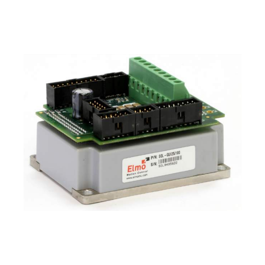
Solo guitar digital servo drive
Hide thumbs
Also See for SimplIQ Series:
- Command reference manual (188 pages) ,
- Installation manual (70 pages)

Subscribe to Our Youtube Channel
Related Manuals for Elmo SimplIQ Series


Summary of Contents for Elmo SimplIQ Series
- Page 1 Solo Guitar Digital Servo Drive Installation Guide October 2017 (Ver. 1.404) www.elmomc.com...
- Page 2 The specifications on which they are based are subject to change without notice. • Elmo Motion Control and the Elmo Motion Control logo are trademarks of Elmo Motion Control Ltd. • Information in this document is subject to change without notice.
- Page 3 Updated the Powerful Digital Output Interface table. Ver. 1.402 February 2013 Updated the Opto Digital Output Interface table. Added a caution and recommendation on the type of cleaning solution to use for the Elmo unit. Ver. 1.403 July 2014 General format changes Ver. 1.404 October 2017 Updated Warranty Information section 1.5 and updated the...
- Page 4 Tel: +49 (0) 7720-85 77 60 • Fax: +49 (0) 7720-85 77 70 • info-de@elmomc.com China Elmo Motion Control Technology (Shanghai) Co. Ltd. Room 1414, Huawen Plaza, No. 999 Zhongshan West Road, Shanghai (200051) China Tel: +86-21-32516651 • Fax: +86-21-32516652 •...
-
Page 5: Table Of Contents
Solo Guitar Installation Guide MAN-SOLGUIIG (Ver. 1.404) Table of Contents Chapter 1: Safety Information ..................8 1.1. Warnings ......................... 9 1.2. Cautions .......................... 9 1.3. Directives and Standards ....................10 1.4. CE Marking Conformance ..................... 10 1.5. Warranty Information ....................10 Chapter 2: Introduction .................... - Page 6 Table of Contents Solo Guitar Installation Guide MAN-SOLGUIIG (Ver. 1.404) 3.8.3. Analog Input ....................46 3.9. Communications ......................47 3.9.1. RS-232 Communication ................. 47 3.9.2. CAN Communication ..................49 3.10. Powering Up ......................... 51 3.11. Initializing the System ....................51 3.12.
- Page 7 Table of Contents Solo Guitar Installation Guide MAN-SOLGUIIG (Ver. 1.404) 4.7.4. Brake ......................71 4.7.5. Analog Input ....................71 4.8. Communications ......................71 4.9. Pulse-Width Modulation (PWM) .................. 72 4.10. Compliance with Standards ..................72...
-
Page 8: Chapter 1: Safety Information
Solo Guitar Installation Guide MAN-SOLGUIIG (Ver. 1.404) Chapter 1: Safety I nform ation In order to operate the Solo Guitar servo drive safely, it is imperative that you implement the safety procedures included in this installation guide. This information is provided to protect you and to keep your work area safe when operating the Solo Guitar and accompanying equipment. -
Page 9: Warnings
7 (8 to 14). The solvent corrodes the plastic cover causing cracks and eventual damage to the drive's PCBs. Elmo recommends using the cleaning fluid Vigon-EFM which is pH Neutral (7). For further technical information on this recommended cleaning fluid, select the link: http://www.zestron.com/fileadmin/zestron.com-usa/daten/electronics/Product_TI1s/TI1-... -
Page 10: Directives And Standards
All Elmo drives are warranted for a period of 12 months from the date of shipment. No other warranties, expressed or implied — and including a warranty of merchantability and fitness for a particular purpose —... -
Page 11: Chapter 2: Introduction
The Solo Guitar drive is easily set up and tuned, using Elmo’s Composer software tools. This Windows-based application enables users to quickly and simply configure the servo drive for SimplIQ optimal use with their motor. -
Page 12: Product Features
Introduction Solo Guitar Installation Guide MAN-SOLGUIIG (Ver. 1.404) The Solo Guitar is available in two models: • The Standard Solo Guitar is a basic servo drive, which operates in current, velocity and position modes including Follower and PT & PVT. It operates simultaneously via RS-232 and CAN DS 301, DS 305, DS 402 communications and features a third-generation programming environment. -
Page 13: Advanced Position Control
Auxiliary emulated, unbuffered, single-ended, encoder output • Tachometer, Potentiometer • Elmo drives provide supply voltage for all the feedback options 2.2.7. Fault Protection The Solo Guitar includes built-in protection against possible fault conditions, including: • Software error handling •... -
Page 14: System Architecture
2.4. How to Use this Guide In order to install and operate your Elmo Solo Guitar servo drive, you will use this manual in conjunction with a set of Elmo documentation. Installation is your first step; after carefully reading the safety instructions in the first chapter, the following chapters provide you with... - Page 15 Introduction Solo Guitar Installation Guide MAN-SOLGUIIG (Ver. 1.404) Figure 2: Elmo Digital Servo Drive Documentation Hierarchy As depicted in the previous figure, this installation guide is an integral part of the Solo Guitar documentation set, comprising: • The SimplIQ Software Manual, which describes the comprehensive software used with the Solo Guitar •...
-
Page 16: Chapter 3: Installation
Solo Guitar Installation Guide MAN-SOLGUIIG (Ver. 1.404) Chapter 3: I nstallation The Solo Guitar must be installed in a suitable environment and properly connected to its voltage supplies and the motor. 3.1. Site Requirements You can guarantee the safe operation of the Solo Guitar by ensuring that it is installed in an appropriate environment. - Page 17 Installation Solo Guitar Installation Guide MAN-SOLGUIIG (Ver. 1.404) It looks like this: The part number at the top gives the type designation as follows: 4. Verify that the Solo Guitar type is the one that you ordered, and ensure that the voltage meets your specific requirements.
-
Page 18: Pinouts
Installation Solo Guitar Installation Guide MAN-SOLGUIIG (Ver. 1.404) 3.3. Pinouts The Solo Guitar has seven connectors (in the connectors version). 3.3.1. Connector Types for the Solo Guitar Type Port Function Pins 5.08 mm Pitch (Figure 3) Power + Motor Power 5.08 mm Pitch (Figure 4) Power + Motor Power (+seven... -
Page 19: Main Power And Motor Power
Installation Solo Guitar Installation Guide MAN-SOLGUIIG (Ver. 1.404) Note: Throughout this chapter there are pairs of diagrams of the Solo Guitar. The diagram on the left is the Solo Guitar with connectors and the diagram on the right shows the product with wires. -
Page 20: Connecting Motor Power
Installation Solo Guitar Installation Guide MAN-SOLGUIIG (Ver. 1.404) Note: When connecting several drives to several motors, all should be wired in the same motor phases and feedback sequences. This will enable the same SimplIQ program to run on all drives. 3.4.1. -
Page 21: Connecting Main Power
Installation Solo Guitar Installation Guide MAN-SOLGUIIG (Ver. 1.404) 3.4.2. Connecting Main Power Power to the Solo Guitar is provided by a 12 to 195 VDC source. A smart control-supply algorithm enables the Solo Guitar to operate with the power supply only, with no need for an auxiliary 24 Volt supply. -
Page 22: Motor (Brake, Ptc)
Installation Solo Guitar Installation Guide MAN-SOLGUIIG (Ver. 1.404) 3.4.3. Motor (Brake, PTC) Signal Function J4/1 BRAKE - Brake (-) (coming from the motor) J4/2 BRAKE + Brake (+) (coming from the motor) J4/3 Motor Protection Sensor (coming from the motor) J4/4 Motor Protection Sensor (coming from the motor) Pin Positions... -
Page 23: Main Feedback For The Solo Guitar
Installation Solo Guitar Installation Guide MAN-SOLGUIIG (Ver. 1.404) 3.5. Main Feedback for the Solo Guitar The Main Feedback port is used to transfer feedback data from the motor to the drive. The Solo Guitar can accept any one of the following devices as a main feedback mechanism: •... - Page 24 Installation Solo Guitar Installation Guide MAN-SOLGUIIG (Ver. 1.404) Figure 7: Main Feedback- Incremental Encoder with Digital Hall Sensors Connection Diagram Figure 8: Main Feedback – Interpolated Analog (Sine/Cosine) Encoder Connection Diagram www.elmomc.com...
- Page 25 Installation Solo Guitar Installation Guide MAN-SOLGUIIG (Ver. 1.404) Figure 9: Main Feedback – Interpolated Analog (Sine/Cosine) Encoder with Digital Hall Sensors Connection Diagram Figure 10: Main Feedback – Resolver Connection Diagram www.elmomc.com...
- Page 26 Installation Solo Guitar Installation Guide MAN-SOLGUIIG (Ver. 1.404) Figure 11: Main Feedback – Resolver and Digital Hall Sensors Connection Diagram www.elmomc.com...
- Page 27 Installation Solo Guitar Installation Guide MAN-SOLGUIIG (Ver. 1.404) Figure 12: Main Feedback – Tachometer Feedback with Digital Hall Sensors Connection Diagram for Brushless Motors Figure 13: Main Feedback – Tachometer Feedback Connection Diagram for Brush Motors www.elmomc.com...
- Page 28 Installation Solo Guitar Installation Guide MAN-SOLGUIIG (Ver. 1.404) Figure 14: Main Feedback – Potentiometer Feedback with Digital Hall Sensors Connection Diagram for Brushless Motors Figure 15: Main Feedback – Potentiometer Feedback Connection Diagram for Brush Motors and Voice Coils www.elmomc.com...
-
Page 29: Main Buffered Output Port
Installation Solo Guitar Installation Guide MAN-SOLGUIIG (Ver. 1.404) 3.6. Main Buffered Output Port This port provides Differential Buffered Outputs (of the Main Feedback) for another axis. Pin (J17) Signal Function CHAO Buffered Channel A output CHAO- Buffered Channel A complement output CHBO Buffered Channel B output CHBO-... - Page 30 Installation Solo Guitar Installation Guide MAN-SOLGUIIG (Ver. 1.404) Figure 16: Main Buffered Output Port (Differential Main Feedback Output) – Connection Diagram www.elmomc.com...
-
Page 31: Auxiliary Feedback (Bi-Directional)
Installation Solo Guitar Installation Guide MAN-SOLGUIIG (Ver. 1.404) 3.7. Auxiliary Feedback (Bi-Directional) When using one of the Auxiliary Feedback options, the relevant functionality of the Auxiliary Feedback's ports are software selected for that option. Refer to the SimplIQ Command Reference Manual for detailed information about Auxiliary Feedback setup. The Auxiliary Feedback connector has two ports: B1 and B2. -
Page 32: Main And Auxiliary Feedback Combinations
Installation Solo Guitar Installation Guide MAN-SOLGUIIG (Ver. 1.404) 3.7.1. Main and Auxiliary Feedback Combinations The Main Feedback is always used in motion control devices whereas Auxiliary Feedback is often, but not always used. The Auxiliary Feedback connector has two ports (B1 and B2). When used in combination with Main Feedback, the Auxiliary Feedback can be set by the software as follows: Auxiliary Feedback: Output... - Page 33 Installation Solo Guitar Installation Guide MAN-SOLGUIIG (Ver. 1.404) Auxiliary Feedback: Input YA[4] = 2 Main (Auxiliary Feedback: input) Feedback Incremental Encoder Input Interpolated Analog (Sine/Cosine) Main Feedback: Encoder Input Incremental Encoder OR Interpolated Resolver Input Auxiliary Feedback: Analog (Sin/Cos) B2: Differential Buffered Encoder Encoder Output of B1 OR Resolver...
- Page 34 Installation Solo Guitar Installation Guide MAN-SOLGUIIG (Ver. 1.404) Auxiliary Feedback: Input YA[4] = 0 Main (Auxiliary Feedback: input) Feedback Incremental Encoder Input Interpolated Analog (Sine/Cosine) Encoder Input Resolver Input Main Feedback: Incremental Encoder Auxiliary Feedback: OR Interpolated B2: Differential Buffered Analog (Sin/Cos) Potentiometer Pulse &...
-
Page 35: Solo Guitar Auxiliary Feedback - Differential Buffered Encoder Output (Ya[4]=4)
Installation Solo Guitar Installation Guide MAN-SOLGUIIG (Ver. 1.404) 3.7.2. Solo Guitar Auxiliary Feedback – Differential Buffered Encoder Output (YA[4]=4 The Auxiliary Feedback’s B2 port can provide emulated encoder signals to other controllers or drives. This option can be used when: •... - Page 36 Installation Solo Guitar Installation Guide MAN-SOLGUIIG (Ver. 1.404) Pin Positions Table 6: Emulated Encoder Output on the Auxiliary Feedback Port B2 - Pin Assignments Figure 17: Emulated Encoder Direct Output – Acceptable Connection Diagram www.elmomc.com...
-
Page 37: Auxiliary Feedback - Differential Encoder Input Option (Ya[4]=2)
Installation Solo Guitar Installation Guide MAN-SOLGUIIG (Ver. 1.404) 3.7.3. Auxiliary Feedback – Differential Encoder Input Option (YA[4]=2) The Solo Guitar can be used as a slave by receiving the position data (on Port B1) of the master encoder in Follower or ECAM mode. In this mode, Port B2 provides differential buffered Auxiliary outputs of B1 for the next slave axis in Follower or ECAM mode. - Page 38 Installation Solo Guitar Installation Guide MAN-SOLGUIIG (Ver. 1.404) Pin Positions Table 7: Differential Auxiliary Encoder Input Option along with Differential Encoder Outputs on Auxiliary Feedback - Pin Assignments www.elmomc.com...
- Page 39 Installation Solo Guitar Installation Guide MAN-SOLGUIIG (Ver. 1.404) Figure 18: Differential Auxiliary Input Option on Auxiliary Feedback - Connection Diagram www.elmomc.com...
-
Page 40: Auxiliary Feedback - Differential Pulse-And-Direction Input Option (Ya[4]=0)
Installation Solo Guitar Installation Guide MAN-SOLGUIIG (Ver. 1.404) 3.7.4. Auxiliary Feedback – Differential Pulse-and-Direction Input Option (YA[4]=0) This mode is used for input of differential pulse-and-direction position commands on Port B1. In this mode Port B2 provides differential buffered pulse-and-direction outputs of B1 for another axis. - Page 41 Installation Solo Guitar Installation Guide MAN-SOLGUIIG (Ver. 1.404) Pin Positions Table 8: Pulse-and-Direction Pin Assignments on Auxiliary Feedback Figure 19: Pulse-and-Direction Input Option on Auxiliary Feedback - Connection Diagram www.elmomc.com...
-
Page 42: I/Os
Installation Solo Guitar Installation Guide MAN-SOLGUIIG (Ver. 1.404) 3.8. I/Os The Solo Guitar has 5 Digital Inputs, 4 Digital Outputs and 1 Analog Input. 3.8.1. Digital Input Each of the pins below can function as an independent input. Pin (J5) Signal Function Programmable input 2 (general purpose, RLS, FLS, INH) - Page 43 Installation Solo Guitar Installation Guide MAN-SOLGUIIG (Ver. 1.404) Figure 20: Digital Input Connection Diagram www.elmomc.com...
-
Page 44: Digital Output
Installation Solo Guitar Installation Guide MAN-SOLGUIIG (Ver. 1.404) 3.8.2. Digital Output Pin (J5) Signal Function VDDIN Digital output supply OUT1 Programmable digital output 1 VDDIN Digital output supply OUT2 Programmable digital output 2 VDDRET Digital output supply return OUT3 Programmable digital output 3 VDDRET Digital output supply return OUT4... - Page 45 Installation Solo Guitar Installation Guide MAN-SOLGUIIG (Ver. 1.404) Figure 21: Digital Output Connection Diagram www.elmomc.com...
-
Page 46: Analog Input
Installation Solo Guitar Installation Guide MAN-SOLGUIIG (Ver. 1.404) 3.8.3. Analog Input Pin (J5) Signal Function ANLIN1+ Analog input 1+ ANLIN1- Analog input 1- ANLRET Analog return Pin Positions Table 11: Analog Input Pin Assignments Figure 22: Analog Input with Single-Ended Source www.elmomc.com... -
Page 47: Communications
Installation Solo Guitar Installation Guide MAN-SOLGUIIG (Ver. 1.404) 3.9. Communications The communication interface may differ according to the user’s hardware. The Solo Guitar can communicate using the following options: • RS-232, full duplex • RS-232 communication requires a standard, commercial 3-core null-modem cable connected from the Solo Guitar to a serial interface on the PC. - Page 48 Installation Solo Guitar Installation Guide MAN-SOLGUIIG (Ver. 1.404) Figure 23: RS-232 Connection Diagram www.elmomc.com...
-
Page 49: Can Communication
Installation Solo Guitar Installation Guide MAN-SOLGUIIG (Ver. 1.404) 3.9.2. CAN Communication To connect the CAN communication cable 1. Connect the shield to the ground of the host (PC). Usually, this connection is soldered internally inside the connector at the PC end. You can use the drain wire to facilitate connection. - Page 50 Installation Solo Guitar Installation Guide MAN-SOLGUIIG (Ver. 1.404) Figure 24: CAN Network Diagram Caution: When installing CAN communication, ensure that each servo drive is allocated a unique ID. Otherwise, the CAN network may hang. www.elmomc.com...
-
Page 51: 3.10. Powering Up
3.11. Initializing the System After the Solo Guitar has been connected and mounted, the system must be set up and initialized. This is accomplished using the Composer, Elmo’s Windows-based software application. Install the application and then perform setup and initialization according to the directions in the Composer Software Manual. - Page 52 Installation Solo Guitar Installation Guide MAN-SOLGUIIG (Ver. 1.404) www.elmomc.com...
-
Page 53: How To Use The Charts
Installation Solo Guitar Installation Guide MAN-SOLGUIIG (Ver. 1.404) 3.12.1. How to Use the Charts The charts above are based upon theoretical worst-case conditions. Actual test results show 30% to 50% better power dissipation. To determine if your application needs a heatsink: 1. -
Page 54: Chapter 4: Technical Specifications
Solo Guitar Installation Guide MAN-SOLGUIIG (Ver. 1.404) Chapter 4: Technical Specifications This chapter provides detailed technical information regarding the Solo Guitar. This includes its dimensions, power ratings, the environmental conditions under which it can be used, the standards to which it complies and other specifications. 4.1. -
Page 55: Feedback Options
Technical Specifications Solo Guitar Installation Guide MAN-SOLGUIIG (Ver. 1.404) 4.1.5. Feedback Options • Incremental Encoder – up to 20 Mega-Counts (5 Mega-Pulse) per second • Digital Halls – up to 2 kHz • Incremental Encoder with Digital Halls for commutation – up to 20 Mega-Counts per second for encoder •... -
Page 56: Built-In Protection
Technical Specifications Solo Guitar Installation Guide MAN-SOLGUIIG (Ver. 1.404) 4.1.7. Built-In Protection • Software error handling • Abort (hard stops and soft stops) • Status reporting • Protection against: Shorts between motor power outputs Shorts between motor power outputs and power input/return ... -
Page 57: Solo Guitar Dimensions
Technical Specifications Solo Guitar Installation Guide MAN-SOLGUIIG (Ver. 1.404) 4.2. Solo Guitar Dimensions Figure 25: Solo Guitar Dimensions www.elmomc.com... -
Page 58: Power Ratings
Technical Specifications Solo Guitar Installation Guide MAN-SOLGUIIG (Ver. 1.404) 4.3. Power Ratings Feature Units Minimum supply voltage Nominal supply voltage Maximum supply voltage Maximum continuous 400 1300 960 1200 1700 1600 2000 480 960 1600 2700 1700 2200 2800 4800 power output Efficiency at rated power (at nominal... -
Page 59: Environmental Conditions
Technical Specifications Solo Guitar Installation Guide MAN-SOLGUIIG (Ver. 1.404) 4.4. Environmental Conditions Feature Details Operating ambient temperature 0 °C to 40 °C (32 °F to 104 °F) according to IEC60068-2-2 Storage temperature -20 °C to +85 °C ( -4 °F to +185 °F) Maximum non-condensing humidity according to IEC60068-2-78 Maximum Operating Altitude... -
Page 60: Velocity Loop
Technical Specifications Solo Guitar Installation Guide MAN-SOLGUIIG (Ver. 1.404) 4.5.2. Velocity Loop Feature Details Controller type Velocity control • Fully digital • Programmable PI and FFW control filters • "On-the-fly" gain scheduling • Automatic, manual and advanced manual tuning Velocity and position feedback •... -
Page 61: Position Loop
Technical Specifications Solo Guitar Installation Guide MAN-SOLGUIIG (Ver. 1.404) 4.5.3. Position Loop Feature Details Controller type “1-2-4” PIP Position command options • Software • Pulse and Direction • Analog Potentiometer Position loop bandwidth < 80 Hz Position sampling time 280 to 400 µsec (4x current loop sample time) Position sampling rate Up to 4 kHz;... -
Page 62: Main Feedback Options
Technical Specifications Solo Guitar Installation Guide MAN-SOLGUIIG (Ver. 1.404) 4.6.2. Main Feedback Options The Solo Guitar can receive and process feedback input from diverse types of devices. 4.6.2.1. Incremental Encoder Input Feature Details Encoder format • A, B and Index •... -
Page 63: Digital Halls
Technical Specifications Solo Guitar Installation Guide MAN-SOLGUIIG (Ver. 1.404) 4.6.2.2. Digital Halls Feature Details Halls inputs • H • Single ended inputs • Built in hysteresis of 1 V for noise immunity Input voltage Nominal operating range: 0 V < V <... -
Page 64: Resolver
Technical Specifications Solo Guitar Installation Guide MAN-SOLGUIIG (Ver. 1.404) 4.6.2.4. Resolver Feature Details Resolver format • Sine/Cosine • Differential Input resistance Differential 2.49 kΩ Resolution Programmable: 10 to 15 bits Maximum electrical frequency (RPS) 512 revolutions/sec Resolver transfer ratio Reference frequency 1/Ts (Ts = sample time in seconds) Reference voltage Supplied by the Solo Guitar... -
Page 65: Potentiometer
Technical Specifications Solo Guitar Installation Guide MAN-SOLGUIIG (Ver. 1.404) 4.6.2.6. Potentiometer Feature Details Potentiometer Format Single-ended Operating Voltage Range 0 to 5 V supplied by the Solo Guitar Potentiometer Resistance 100 Ω to 1 kΩ … above this range, linearity is affected detrimentally Input Resistance 100 kΩ... -
Page 66: Auxiliary Feedback Port (Output Mode Ya[4]= 4)
Technical Specifications Solo Guitar Installation Guide MAN-SOLGUIIG (Ver. 1.404) 4.6.4. Auxiliary Feedback Port (output mode YA[4]= 4) Feature Details Emulated output • A, B, Index • Differential Output current capability • Maximum output current: I (max) = 2 mA • High level output voltage: V >... -
Page 67: Auxiliary Feedback Port (Input Mode Ya[4]= 2, 0)
Technical Specifications Solo Guitar Installation Guide MAN-SOLGUIIG (Ver. 1.404) 4.6.5. Auxiliary Feedback Port (input mode YA[4]= 2, 0) Feature Details Encoder input, • A, B, Index pulse and direction input • Differential Input voltage Low: 0 V < V < 0.8 V High: 2 V <... -
Page 68: I/Os
Technical Specifications Solo Guitar Installation Guide MAN-SOLGUIIG (Ver. 1.404) 4.7. I/Os The Solo Guitar has: • 5 Digital Inputs • 4 Digital Outputs • 1 Analog Input 4.7.1. Digital Input Interfaces Feature Details Type of input Optically isolated Input current Rin=3.43K, Iin = 1.2 mA @ Vin = 5 V for all inputs Rin=3.43K, Iin = 6.7 mA @ Vin = 24 V... -
Page 69: Powerful Digital Output Interface
Technical Specifications Solo Guitar Installation Guide MAN-SOLGUIIG (Ver. 1.404) 4.7.2. Powerful Digital Output Interface Feature Details Type of output • Optically isolated • Powerful Source capability VDD Supply Range 15 V to 30 V Max. output current Iout1 (max) ≤ 500 mA Iout (max) Iout2, 3, 4 (max) ≤... -
Page 70: Opto Digital Output Interface
Technical Specifications Solo Guitar Installation Guide MAN-SOLGUIIG (Ver. 1.404) 4.7.3. Opto Digital Output Interface Feature Details Type of output • Optically isolated • Open emitter VDD Supply Range 2.5 V to 30 V Max. output current (max) ≤ 8 mA Iout (max) VOL ≤... - Page 71 Technical Specifications Solo Guitar Installation Guide MAN-SOLGUIIG (Ver. 1.404) 4.7.4. Brake The brake can be controlled by Digital Output 1. Digital Output 1 should be set to Brake. Feature Details Rated voltage 24 V +10% Rated current 0.5 A Input power 12 W 4.7.5.
- Page 72 Technical Specifications Solo Guitar Installation Guide MAN-SOLGUIIG (Ver. 1.404) 4.9. Pulse-Width Modulation (PWM) Feature Details PWM resolution 12-bit PWM switching frequency on the load 2/Ts (factory default 22 kHz on the motor) 4.10. Compliance with Standards Specification Details Quality Assurance ISO 9001:2008 Quality Management Design...
- Page 73 In compliance with 2002/96/EC Waste Electrical and Electronic Equipment regulations (WEEE) Note: Out-of-service Elmo drives should be sent to the nearest Elmo sales office. In compliance with 2002/95/EC Restrictions on Application of Hazardous (effective July 2006) Substances in Electric and Electronic Equipment (RoHS) www.elmomc.com...
Need help?
Do you have a question about the SimplIQ Series and is the answer not in the manual?
Questions and answers