Sign In
Upload
Manuals
Brands
Elmo Manuals
Servo Drives
SimplIQ Series
Elmo SimplIQ Series Manuals
Manuals and User Guides for Elmo SimplIQ Series. We have
3
Elmo SimplIQ Series manuals available for free PDF download: Command Reference Manual, Installation Manual
Elmo SimplIQ Series Command Reference Manual (188 pages)
Brand:
Elmo
| Category:
Servo Drives
| Size: 1 MB
Table of Contents
Table of Contents
3
Chapter 1: Introduction
6
Command Specification
6
Scope
7
Chapter 2: Functional Listing
8
Motion Commands
8
I/O Commands
9
Status Commands
9
Feedback Commands
9
Configuration Commands
10
Communication Commands
11
Control Filter Commands
11
Protection Commands
11
Data Recording Commands
12
2.10 User Program Commands
12
2.11 General Commands
13
Chapter 3: Alphabetical Listing
14
Limit Ranges
16
AB[N] - Absolute Encoder Setting Parameters
17
AC - Acceleration
19
AG[N] - Analog Gains Array
20
AN[N] - Analog Inputs Array
21
AS[N] - Analog Input Offsets Array
22
BG - Begin Motion
23
BH - Get a Single Recorded Signal as Hexadecimal
24
BP[N] - Brake Parameter
25
BT - Begin Motion at Defined Time
26
BV - Maximum Motor DC Voltage
27
CA[N] - Commutation Array
28
CC - Compiled Program Ready
34
CD - CPU Dump
35
CL[N] - Current Continuous Limitations and Motor Stuck Protection Parameters
37
CP - Clear Program
39
DC - Deceleration
40
DD - CAN Controller Status
41
DF/DS - Download Firmware
42
DL - Download Program
43
DV[N] - Reference Desired Value
44
EC - Error Code
45
EF[N] - Encoder Filter Frequency
58
EM[N] - ECAM Parameters
60
EO - Echo Mode
62
ER[N] - Maximum Tracking Error
63
ET[N] - Entries for ECAM Table
64
FF[N] - Feed Forward
65
FR[N] - Follower Ratio
66
GS[N] - Gain Scheduling
67
HL[N] - Over-Speed Limit and Position Range Limit
69
HM[N] - Homing, Capture and Flag
70
HP - Halt Program Execution
73
HX - Hexadecimal Mode
74
HY[N] - Auxiliary Homing, Capture and Flag
75
IB[N] - Input Bits Array
78
ID, IQ - Read Active Current and Reactive Current
79
IF[N] - Digital Input Filter
80
IL[N] - Input Logic
81
IP - Input Port
88
JV- Jogging Velocity
90
KG[N] - Gain Scheduled Controller Parameters
91
KI[N], KP[N] - PI Parameters
92
KL - Kill Motion and Program
93
KV[N] - High-Order Controller Filter Parameters
94
LC - Current Limit Flag
95
LD - Load Parameters from Flash
96
LL[N] - Low Feedback Limit
97
LP[N] - List Properties
98
LS - List User Program
99
MC - Maximum Peak Driver Current
100
MF - Motor Failure
101
MI - Mask Interrupt
104
MO - Motor Enable/Disable
106
MP[N] - Motion (PT/PVT) Parameters
108
MS - Motion Status
110
OB[N] - Output Bits Array
111
OC[N] - Output Compare
113
OL[N] - Output Logic
116
OP - Output Port
118
PA - Absolute Position
119
PE - Position Error
120
PK - Peak Memory
121
PL[N] - Peak Duration and Limit
122
PM - Profiler Mode
124
PP[N] - Protocol Parameters
125
PR - Relative Position
127
PS - Program Status
128
PT - Position Time Command
129
PV - Position Velocity Time Command
130
PW[N] - PWM Signal Parameters
131
PX - Main Position
132
PY - Auxiliary Position
133
QP[N], QT[N], QV[N] - Position, Time, Velocity
134
RC - Define Recorded Variables
135
RG - Recorder Gap
136
RL - Record Length
137
RM - Reference Mode
138
RP[N] - Recorder Parameters
139
RR - Activate Recorder / Get Recorder Status
141
RS - Soft Reset
142
RV[N] - Recorded Variables
143
SD - Stop Deceleration
144
SF - Smooth Factor
145
SN - Serial Number
146
SP - Speed for PTP Mode
147
SR - Status Register
148
ST - Stop Motion
150
SV - Save Parameters to Flash
151
TC - Torque Command
152
TI[N] - Temperature Indications Array
153
TM - System Time
154
TP[N] - Floating Wizard Parameters
155
TR - Target Radius
156
TS - Sampling Time
157
TW[N] - Wizard Command
158
UF[N] - User Float Array
159
UI[N] - User Integer
160
UM - Unit Mode
161
VE - Velocity Error
163
VH[N], VL[N] - High and Low Reference Limit
164
VR - Firmware Version
165
VX, VY - Velocity of Main and Auxiliary Feedback
166
WI[N] - Miscellaneous Reports, Integer
167
WS[N] - Miscellaneous Reports
168
XA[N] - Extra Parameters (More)
173
XC, XQ - Execute or Continue Program
174
XM[N] - X Modulo
175
XP[N] - Extra Parameters
176
YA[N] - Auxiliary Position Sensor Parameters
178
YM[N] - y Modulo
180
ZP[N] - Integer Wizard Parameters
181
ZX[N] - User Program and Auto-Tuning Temporary Storage
182
Index
183
Advertisement
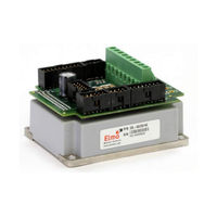
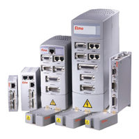
Elmo SimplIQ Series Installation Manual (73 pages)
Solo Guitar Digital Servo Drive
Brand:
Elmo
| Category:
Servo Drives
| Size: 4 MB
Table of Contents
Table of Contents
5
Chapter 1: Safety Information
8
Warnings
9
Cautions
9
Directives and Standards
10
CE Marking Conformance
10
Warranty Information
10
Chapter 2: Introduction
11
Drive Description
11
Product Features
12
Current Control
12
Velocity Control
12
Position Control
12
Advanced Position Control
13
Communication Options
13
Feedback Options
13
Fault Protection
13
System Architecture
14
How to Use this Guide
14
Chapter 3: Installation
16
Site Requirements
16
Unpacking the Drive Components
16
Pinouts
18
Connector Types for the solo Guitar
18
Main Power and Motor Power
19
Connecting Motor Power
20
Connecting Main Power
21
Motor (Brake, PTC)
22
Main Feedback for the solo Guitar
23
Main Buffered Output Port
29
Auxiliary Feedback (Bi-Directional)
31
Main and Auxiliary Feedback Combinations
32
Solo Guitar Auxiliary Feedback - Differential Buffered Encoder Output (YA[4]=4)
35
Auxiliary Feedback - Differential Encoder Input Option (YA[4]=2)
37
Auxiliary Feedback - Differential Pulse-And-Direction Input Option (YA[4]=0)
40
I/Os
42
Digital Input
42
Digital Output
44
Analog Input
46
Communications
47
RS-232 Communication
47
CAN Communication
49
3.10. Powering up
51
3.11. Initializing the System
51
3.12. Heat Dissipation
51
How to Use the Charts
53
Chapter 4: Technical Specifications
54
Features
54
Motion Control Modes
54
Advanced Positioning Control Modes
54
Advanced Filters and Gain Scheduling
54
Fully Programmable
54
Feedback Options
55
Input/Output
55
Built-In Protection
56
Accessories
56
Status Indication
56
Automatic Procedures
56
Solo Guitar Dimensions
57
Power Ratings
58
Auxiliary Supply
58
Environmental Conditions
59
Control Specifications
59
Current Loop
59
Velocity Loop
60
Position Loop
61
Feedbacks
61
Feedback Supply Voltage
61
Main Feedback Options
62
Incremental Encoder Input
62
Digital Halls
63
Interpolated Analog (Sine/Cosine) Encoder
63
Resolver
64
Tachometer
64
Potentiometer
65
Main Encoder Buffered Output
65
Auxiliary Feedback Port (Output Mode YA[4]= 4)
66
Auxiliary Feedback Port (Input Mode YA[4]= 2, 0)
67
I/Os
68
Digital Input Interfaces
68
Powerful Digital Output Interface
69
Opto Digital Output Interface
70
Elmo SimplIQ Series Installation Manual (70 pages)
Digital Servo Drive
Brand:
Elmo
| Category:
Servo Drives
| Size: 3 MB
Table of Contents
Table of Contents
5
Chapter 1: Safety Information
7
Warnings
8
Cautions
8
Directives and Standards
9
CE Marking Conformance
9
Warranty Information
9
Chapter 2: Introduction
10
Drive Description
10
Product Features
10
Current Control
10
Velocity Control
11
Position Control
11
Advanced Position Control (Advanced Model Only)
11
Communication Options
11
Feedback Options
12
Fault Protection
12
System Architecture
13
How to Use this Guide
13
Chapter 3: Installation
15
Before You Begin
15
Site Requirements
15
Hardware Requirements
15
Unpacking the Drive Components
17
Mounting the Cello
18
Connecting the Cables
19
Wiring the Cello
19
Connecting the Power Cables
22
Connecting the Motor Cable
22
Connecting the Main Power Cable
23
Connecting the Optional Backup Supply Cable (24V)
24
Feedback and Control Cable Assemblies
25
Main Feedback Cable (FEEDBACK A)
25
Main and Auxiliary Feedback Combinations
34
Auxiliary Feedback (FEEDBACK B)
35
Main Encoder Buffered Outputs or Emulated Encoder Outputs Option on FEEDBACK B (YA[4]=4)
35
Differential Auxiliary Encoder Input Option on FEEDBACK B (YA[4]=2)
38
Single-Ended Auxiliary Input Option on FEEDBACK B
40
Pulse-And-Direction Input Option on FEEDBACK B (YA[4]=0)
42
I/O Cables
46
General I/O Port (J1)
46
General Input Port (J2)
48
Communication Cables
50
RS-232 Communication
50
Canopen Communication
51
Powering up
53
Initializing the System
53
Chapter 4: Technical Specifications
54
Features
54
Motion Control Modes
54
Advanced Positioning Motion Control Modes
54
Advanced Filters and Gain Scheduling
54
Fully Programmable
54
Feedback Options
55
Input/Output
55
Built-In Protection
56
Cello Dimensions
57
Power Ratings
58
Environmental Conditions
58
Cello Connections
59
Backup Supply (Optional)
60
Control Specifications
60
Current Loop
60
Velocity Loop
61
Position Loop
61
Feedbacks
62
Feedback Supply Voltage
62
Incremental Encoder Input
62
Digital Halls
63
Interpolated Analog (Sine/Cosine) Encoder
63
Resolver
64
Tachometer
64
Potentiometer
65
Encoder Outputs
65
I/Os
65
Digital Input Interfaces
66
Digital Output Interface
67
Analog Input
68
Communications
68
Pulse-Width Modulation (PWM)
68
4.11. Mechanical Specifications
68
4.12. Compliance with Standards
69
Advertisement
Advertisement
Related Products
Elmo SimpliQ Line
Elmo SimplIQ Tuba TUB Series
Elmo SimplIQ Tuba TUB-I Series
Elmo SimplIQ Tuba TUB-R Series
Elmo SimplIQ Tuba TUB-T Series
Elmo SimplIQ Tuba TUB-Q Series
Elmo QBiC S X1
Elmo SN2230 IP II
Elmo DUO Series
Elmo ST-600D
Elmo Categories
Document Camera
Projector
Security Camera
Digital Presenters
Servo Drives
More Elmo Manuals
Login
Sign In
OR
Sign in with Facebook
Sign in with Google
Upload manual
Upload from disk
Upload from URL