Advertisement
Quick Links
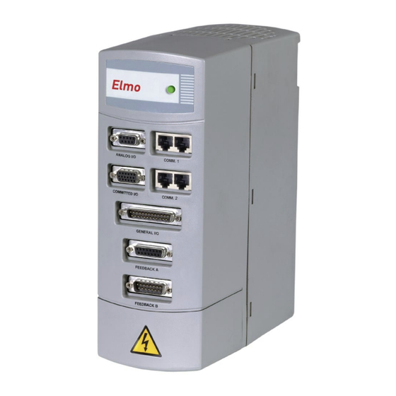
Elmo Motion Control TUB-20/230GE
Digital Servo Drive
A l l t r a d e m a r k s , b r a n d n a m e s , a n d b r a n d s a p p e a r i n g h e r e i n a r e t h e p r o p e r t y o f t h e i r r e s p e c t i v e o w n e r s .
• C r i t i c a l a n d e x p e d i t e d s e r v i c e s
• I n s t o c k / R e a d y - t o - s h i p
Artisan Scientific Corporation dba Artisan Technology Group is not an affiliate, representative, or authorized distributor for any manufacturer listed herein.
$
750
.00
In Stock
Qty Available: 5+
Used and in Good Condition
Open Web Page
https://www.artisantg.com/65776-1
• We b u y y o u r e x c e s s , u n d e r u t i l i z e d , a n d i d l e e q u i p me n t
• F u l l - s e r v i c e , i n d e p e n d e n t r e p a i r c e n t e r
Advertisement

Subscribe to Our Youtube Channel
Related Manuals for Elmo SimplIQ TUB-20


Summary of Contents for Elmo SimplIQ TUB-20
- Page 1 Elmo Motion Control TUB-20/230GE Digital Servo Drive In Stock Qty Available: 5+ Used and in Good Condition Open Web Page https://www.artisantg.com/65776-1 A l l t r a d e m a r k s , b r a n d n a m e s , a n d b r a n d s a p p e a r i n g h e r e i n a r e t h e p r o p e r t y o f t h e i r r e s p e c t i v e o w n e r s .
- Page 2 Tuba Digital Servo Drive Installation Guide October 2017 (Ver. 1.503) www.elmomc.com...
- Page 3 The specifications on which they are based are subject to change without notice. • Elmo Motion Control and the Elmo Motion Control logo are trademarks of Elmo Motion Control Ltd. • Information in this document is subject to change without notice.
- Page 4 MTCR 07-009-56: Added note to Section 3.4.8.1 July 2012 Formatted according to the new template 1.501 February 2013 Added a caution and recommendation on the type of cleaning solution to use for the Elmo unit. 1.502 July 2014 General format changes 1.503 October 2017 Updated the Warranty Information section 1.5 and the...
- Page 5 Tel: +49 (0) 7720-85 77 60 • Fax: +49 (0) 7720-85 77 70 • info-de@elmomc.com China Elmo Motion Control Technology (Shanghai) Co. Ltd. Room 1414, Huawen Plaza, No. 999 Zhongshan West Road, Shanghai (200051) China Tel: +86-21-32516651 • Fax: +86-21-32516652 •...
- Page 6 Tuba Installation Guide MAN-TUBIG (Ver. 1.503) Table of Contents Chapter 1: Safety Information ..................8 1.1. Warnings ......................... 9 1.2. Cautions .......................... 9 1.3. Directives and Standards ....................10 1.4. CE Marking Conformance ..................... 10 1.5. Warranty Information ....................10 Chapter 2: Introduction ....................
- Page 7 Table of Contents Tuba Installation Guide MAN-TUBIG (Ver. 1.503) 3.4.4. Feedback and Control Cable Assemblies ............30 3.4.5. Main Feedback Cable (Feedback A) ............... 30 3.4.6. Main and Auxiliary Feedback Combinations ..........39 3.4.7. Auxiliary Feedback (FEEDBACK B) ..............41 3.4.7.1.
- Page 8 Table of Contents Tuba Installation Guide MAN-TUBIG (Ver. 1.503) 4.9.5. Resolver ......................71 4.9.6. Tachometer....................71 4.9.7. Potentiometer ....................72 4.9.8. Encoder Outputs .................... 72 4.10. I/Os ..........................73 4.10.1. Digital Input Interfaces (on the GENERAL I/O port) ........73 4.10.2.
- Page 9 Tuba Installation Guide MAN-TUBIG (Ver. 1.503) Chapter 1: Safety I nform ation In order to achieve the optimum, safe operation of the Tuba servo drive, it is imperative that you implement the safety procedures included in this installation guide. This information is provided to protect you and to keep your work area safe when operating the Tuba and accompanying equipment.
- Page 10 7 (8 to 14). The solvent corrodes the plastic cover causing cracks and eventual damage to the drive's PCBs. Elmo recommends using the cleaning fluid Vigon-EFM which is pH Neutral (7). For further technical information on this recommended cleaning fluid, select the link: http://www.zestron.com/fileadmin/zestron.com-usa/daten/electronics/Product_TI1s/TI1-...
- Page 11 All Elmo drives are warranted for a period of 12 months from the date of shipment. No other warranties, expressed or implied — and including a warranty of merchantability and fitness for a particular purpose —...
- Page 12 The Tuba can operate as a stand-alone device or as part of a multi-axis network in a distributed configuration. The Tuba drive is set up and tuned using Elmo’s Composer software. This Windows-based application enables users to quickly and simply configure the servo drive for optimal use with their motor.
- Page 13 Introduction Tuba Installation Guide MAN-TUBIG (Ver. 1.503) 2.2.2. Velocity Control • Fully digital • Programmable PI and FFW (feed forward) control filters • Sample rate two times current loop sample time • “On-the-fly” gain scheduling • Automatic, manual and advanced manual tuning and determination of optimal gain and phase margins 2.2.3.
- Page 14 0 to 5 V voltage range Resistance: 100 Ω to 1000 Ω • Elmo drives provide supply voltage for all the feedback options. 2.2.7. Fault Protection The Tuba includes built-in protection against possible fault conditions, including: • Software error handling •...
- Page 15 Introduction Tuba Installation Guide MAN-TUBIG (Ver. 1.503) 2.3. System Architecture Tachometer Communication Potentiometer RS 232 and CANopen Analog Encoder Resolver Incremental Encoder Controller I/Os Auxiliary Power 24 VDC Supply Auxiliary Encoder Protection Current Feedback Incremental Encoder Buffered Output Power Stage Emulated Output Figure 1: Tuba System Block Diagram www.elmomc.com...
- Page 16 2.4. How to Use this Guide In order to install and operate your Elmo Tuba servo drive, you will use this manual in conjunction with a set of Elmo documentation. Installation is your first step; after carefully reading the safety instructions in the first chapter, the following chapters provide you with installation instructions as follows: •...
- Page 17 Tuba Installation Guide MAN-TUBIG (Ver. 1.503) Chapter 3: I nstallation The Tuba must be installed in a suitable environment and properly connected to its voltage supplies and the motor. 3.1. Before You Begin 3.1.1. Site Requirements You can guarantee the safe operation of the Tuba by ensuring that it is installed in an appropriate environment.
- Page 18 Installation Tuba Installation Guide MAN-TUBIG (Ver. 1.503) 3.1.2.3. Power Connectors Component Connector Described Photo in Section External DC Link B1, B2 on External DC 3.4.2.3 Cable Link Cable Main Power Cable PE, AC1, AC2, and AC3 3.4.2.2 on Power Connector Motor Cable M1, M2, M3, PE 3.4.2.1...
- Page 19 Installation Tuba Installation Guide MAN-TUBIG (Ver. 1.503) 3.1.2.5. Feedback and I/O Connectors Component Port on Tuba Described Diagram in Section Analog Inputs ANALOG I/O 3.4.8.1 (if needed) CEL0040A-DWG COR016A Digital Outputs COMMITTED I/O 3.4.8.2 Cable (if needed) Digital Inputs Cable GENERAL I/O 3.4.8.3 (if needed)
- Page 20 Installation Tuba Installation Guide MAN-TUBIG (Ver. 1.503) 3.1.2.6. Other Items Needed Component Diagram PC for drive setup and tuning Motor data sheet or manual 3.2. Unpacking the Drive Components Before you begin working with the Tuba system, verify that you have all of its components, as follows: •...
- Page 21 Installation Tuba Installation Guide MAN-TUBIG (Ver. 1.503) 3.3. Mounting the Tuba The Tuba has been designed for two standard mounting options: • Attaching directly to the wall with screws • Mounting on a DIN rail With either type of mounting, be sure to leave about 10 cm (4 in) above and below the instrument for heat dissipation.
- Page 22 Installation Tuba Installation Guide MAN-TUBIG (Ver. 1.503) 3.3.2. Mounting on a DIN Rail At the top rear of the Tuba, a horizontal groove lets you quickly and easily snap the drive onto a DIN rail in your work area. To mount the Tuba on a DIN rail: 1.
- Page 23 Installation Tuba Installation Guide MAN-TUBIG (Ver. 1.503) 3. Press the Tuba down to a vertical position until it clicks onto the DIN rail. Figure 6: Tuba Mounted on a DIN Rail 3.4. Connecting the Cables The Tuba has 11 connectors. 3.4.1.
- Page 24 Installation Tuba Installation Guide MAN-TUBIG (Ver. 1.503) • Keep the motor wires as far away as possible from the feedback, control and communication cables. Ensure that in normal operating conditions, the shielded wires and drain carry no current. • The only time these conductors carry current is under abnormal conditions, when electrical equipment has become a potential shock or fire hazard while conducting external EMI interferences directly to ground, in order to prevent them from affecting the drive.
- Page 25 Installation Tuba Installation Guide MAN-TUBIG (Ver. 1.503) Type Function Port on Tuba Connector Location Table 1: Connectors on the Tuba www.elmomc.com...
- Page 26 Installation Tuba Installation Guide MAN-TUBIG (Ver. 1.503) Figure 7: Tuba Detailed Connection Diagram www.elmomc.com...
- Page 27 Tuba Installation Guide Installation MAN-TUBIG (Ver. 1.503) 3.4.2. Connecting the Power Cables Access the power terminal connections on the Tuba servo drive by removing the front safety cover located at the bottom of the front panel of the unit, as shown below: Figure 8: Removable Bottom Panel After removing the safety cover, the power terminal connections are visible, as follows: Figure 9: Tuba Power Connectors...
- Page 28 Installation Tuba Installation Guide MAN-TUBIG (Ver. 1.503) 3.4.2.1. Connecting the Motor Cable Connect the motor power cable to the M1, M2, M3 and PE terminals of the main power connector. The phase connection order is arbitrary because the Composer will establish the proper commutation automatically during setup.
- Page 29 Installation Tuba Installation Guide MAN-TUBIG (Ver. 1.503) 3.4.2.2. Connecting the Main Power Cable Connect the main power supply cable to the AC1, AC2 and AC3 terminals of the main power connector. Connect the Protective Earth wire to the nearest PE terminal on the terminal block. Notes for connecting the AC power cable: •...
- Page 30 Installation Tuba Installation Guide MAN-TUBIG (Ver. 1.503) 3.4.3. Connecting the Auxiliary Supply Cable (24 V) Connect the auxiliary supply to the 24 VDC terminal block on the bottom of the Tuba. Remember, you are working with DC power; so be sure to exercise caution. Notes for 24 VDC auxiliary supply connections: •...
- Page 31 Installation Tuba Installation Guide MAN-TUBIG (Ver. 1.503) 3.4.4. Feedback and Control Cable Assemblies The Tuba features easy-to-use D-Sub type connections for all Control and Feedback cables. Below are instructions and diagrams describing how to assemble those cables. • Use 24, 26 or 28 AWG twisted-pair shielded cables (24 AWG cable is recommended). For best results, the shield should have aluminum foil covered by copper braid.
- Page 32 Installation Tuba Installation Guide MAN-TUBIG (Ver. 1.503) FEEDBACK A on the front of the Tuba has a 15-pin D-Sub socket. Connect the Main Feedback cable from the motor to FEEDBACK A using a 15-pin, D-Sub plug with a metal housing. When assembling the Main Feedback cable, follow the instructions in Section 3.4.4 (Feedback and Control Cable Assemblies).
- Page 33 Installation Tuba Installation Guide MAN-TUBIG (Ver. 1.503) Absolute Encoders TUB-XX/YYYQ Signal Heidenhain Stegmann Hall C Hall C Hall A Hall A SUPRET Supply return Supply return EnDat (Heidenhain) Encoder +5 Halls supply +5V supply Sine A complement Sine A Sine A Sine A complement DATA- Data complement...
- Page 34 Installation Tuba Installation Guide MAN-TUBIG (Ver. 1.503) Incremental Encoder Tuba Feedback A with Hall Sensor Hall C Hall B Hall A CHA- CHA- CHB- CHB- INDEX INDEX INDEX- INDEX- Encoder / Hall +5v Supply Hall / Encoder Supply / Voltage Return SUPRET TUB0004A Figure 15: Main Feedback- Incremental Encoder with Digital Hall Sensor - Connection...
- Page 35 Installation Tuba Installation Guide MAN-TUBIG (Ver. 1.503) Tuba Sine / Cosine Feedback A Encoder Encoder +5v Supply SUPRET Encoder Supply Return TUB0005A Figure 16: Main Feedback – Interpolated Analog (Sine/Cosine) Encoder Connection Diagram Tuba Resolver Feedback A TUB0006A Figure 17: Main Feedback – Resolver Connection Diagram www.elmomc.com...
- Page 36 Installation Tuba Installation Guide MAN-TUBIG (Ver. 1.503) only one tachometer port is available at a time Figure 18: Main Feedback – Tachometer Feedback with Digital Hall Sensor Connection Diagram for Brushless Motors Figure 19: Main Feedback – Tachometer Feedback Connection Diagram www.elmomc.com...
- Page 37 Installation Tuba Installation Guide MAN-TUBIG (Ver. 1.503) Figure 20: Main Feedback – Potentiometer Feedback with Digital Hall Sensors Connection Diagram for Brushless Motors Figure 21: Main Feedback – Potentiometer Feedback Connection Diagram www.elmomc.com...
- Page 38 Installation Tuba Installation Guide MAN-TUBIG (Ver. 1.503) Figure 22: Main Feedback – Stegmann Feedback Connection Diagram www.elmomc.com...
- Page 39 Installation Tuba Installation Guide MAN-TUBIG (Ver. 1.503) Figure 23: Main Feedback – Heidenhain Feedback Connection Diagram www.elmomc.com...
- Page 40 Installation Tuba Installation Guide MAN-TUBIG (Ver. 1.503) 3.4.6. Main and Auxiliary Feedback Combinations The Main Feedback is always used in motion control devices whereas Auxiliary Feedback is often, but not always used. The Auxiliary Feedback connector on the Tuba, FEEDBACK B has two ports, Port B1 and Port B2.
- Page 41 Installation Tuba Installation Guide MAN-TUBIG (Ver. 1.503) FEEDBACK B Ports B1 and B2 FEED- YA[4] = 4 YA[4] = 2 YA[4] = 0 BACK A Potentiometer - input - input - input Incremental Incremental - input Differential Input Encoder Differential or Encoder - output...
- Page 42 Installation Tuba Installation Guide MAN-TUBIG (Ver. 1.503) 3.4.7. Auxiliary Feedback (FEEDBACK B) When using one of the auxiliary feedback options, the relevant functionality of FEEDBACK B ports are software selected for that option. Refer to the Tuba Command Reference Manual for detailed information about FEEDBACK B setup.
- Page 43 Installation Tuba Installation Guide MAN-TUBIG (Ver. 1.503) FEEDBACK B, on the front of the Tuba, has a 15-pin D-Sub plug. Connect the Auxiliary Feedback cable, from the controller or other device, to FEEDBACK B using a 15-pin D-Sub socket with a metal housing.
- Page 44 Installation Tuba Installation Guide MAN-TUBIG (Ver. 1.503) 3.4.7.2. Differential Auxiliary Encoder Input Option on FEEDBACK B (YA[4]=2) The Tuba can be used as a slave by receiving the position of the master encoder data (on Port B1) in Follower or ECAM mode. In this mode Port B2 provides differential buffered auxiliary outputs for the next slave axis in follower or ECAM mode.
- Page 45 Installation Tuba Installation Guide MAN-TUBIG (Ver. 1.503) Tuba Tuba Tuba Tuba Figure 25: Differential Auxiliary Encoder Input Option on FEEDBACK B - Connection Diagram www.elmomc.com...
- Page 46 Installation Tuba Installation Guide MAN-TUBIG (Ver. 1.503) 3.4.7.3. Single-Ended Auxiliary Input Option on FEEDBACK B - (YA[4]=2) The Tuba can be used as a slave by receiving the position data of the master encoder (on Port B1) in Follower or ECAM mode. In this mode Port B2 provides differential buffered auxiliary outputs for the next slave axis in Follower or ECAM mode.
- Page 47 Installation Tuba Installation Guide MAN-TUBIG (Ver. 1.503) Tuba Tuba Tuba Tuba Figure 26: Single-Ended Auxiliary Input Option on FEEDBACK B - Connection Diagram www.elmomc.com...
- Page 48 Installation Tuba Installation Guide MAN-TUBIG (Ver. 1.503) 3.4.7.4. Pulse-and-Direction Input Option on FEEDBACK B - (YA[4]=0) This mode is used for input of differential or single-ended pulse-and-direction position commands on Port B1. In this mode Port B2 provides differential buffered pulse-and-direction outputs for another axis.
- Page 49 Installation Tuba Installation Guide MAN-TUBIG (Ver. 1.503) FEEDBACK B on the front of the Tuba has a 15-pin D-Sub plug. Connect the Auxiliary Feedback cable from the Pulse and Direction Controller to FEEDBACK B using a 15-pin D-Sub socket with a metal housing.
- Page 50 Installation Tuba Installation Guide MAN-TUBIG (Ver. 1.503) Figure 28: Differential Pulse-and-Direction Input Option on FEEDBACK B - Connection Diagram www.elmomc.com...
- Page 51 Installation Tuba Installation Guide MAN-TUBIG (Ver. 1.503) 3.4.8. I/O Cables The Tuba has three I/O ports (ANALOG INPUTS, DIGITAL INPUTS and DIGITAL OUTPUTS) which can be used to connect 2 analog inputs, 10 separate digital inputs and 6 separate digital outputs: LABEL ANALOG INPUTS...
- Page 52 Installation Tuba Installation Guide MAN-TUBIG (Ver. 1.503) Tuba - Figure 29: Analog Inputs Connection Diagram 3.4.8.2. Digital Inputs (on the GENERAL I/O Port) The Tuba servo drive is equipped with a 25-pin D-Sub plug for digital inputs. When assembling an I/O cable for digital input follow the instructions in Section 3.4.4 (Feedback and Control Cable Assemblies) using a 25-pin D-Sub socket with a metal case.
- Page 53 Installation Tuba Installation Guide MAN-TUBIG (Ver. 1.503) Signal Function Pin Positions Programmable input 3 Programmable input 2 Programmable input 1 INRET10 Programmable inputs return 10 INRET9 Programmable inputs return 9 INRET8 Programmable inputs return 8 INRET7 Programmable inputs return 7 N.C.
- Page 54 Installation Tuba Installation Guide MAN-TUBIG (Ver. 1.503) Figure 30: Digital Inputs (on the General I/O port) Connection Diagram www.elmomc.com...
- Page 55 Installation Tuba Installation Guide MAN-TUBIG (Ver. 1.503) 3.4.8.3. Digital Outputs (on the COMMITTED I/O Port) The Tuba servo drive is equipped with a 15-pin, high-density, D-Sub socket for digital outputs. When assembling an I/O cable for digital outputs follow the instructions in Section 3.4.4 (Feedback and Control Cable Assemblies) using a 15-pin high density D-Sub plug with a metal case.
- Page 56 Installation Tuba Installation Guide MAN-TUBIG (Ver. 1.503) Tuba Digital Outputs Figure 31: Digital Outputs (on the COMMITTED I/O port) Connection Diagram www.elmomc.com...
- Page 57 Installation Tuba Installation Guide MAN-TUBIG (Ver. 1.503) 3.4.9. Communication Cables The communication cables use an 8-pin RJ-45 plug that connect to the RS-232 and CAN ports on the front of the Tuba. The communication interface may differ according to the user’s hardware. The Tuba can communicate using the following options: a.
- Page 58 Installation Tuba Installation Guide MAN-TUBIG (Ver. 1.503) Note: Only one RS-232 port can be used at a time. Figure 32: RS-232 Connection Diagram 3.4.9.2. CAN Communication (on the COMM.2 Ports) Notes for connecting the CAN communication cable: • Use 26 or 28 AWG twisted pair shielded cables. For best results, the shield should have aluminum foil and covered by copper braid with a drain wire.
- Page 59 Installation Tuba Installation Guide MAN-TUBIG (Ver. 1.503) Tuba 1 CAN - Controller CAN - Interface Drain Wire CAN_H 120Ω CAN_L CAN_GND Shield of RJ connector Drain Wire CAN_GND Tuba 2 CAN - Interface Drain Wire CAN_H CAN_L CAN_GND Shield of RJ connector Drain Wire CAN_GND...
- Page 60 After the Tuba has been connected and mounted, the system must be set up and initialized. This is accomplished using the Composer, Elmo’s Windows-based software application. Install the application and then perform setup and initialization according to the directions in the Composer Software Manual.
- Page 61 Tuba Installation Guide MAN-TUBIG (Ver. 1.503) Chapter 4: Technical Specifications This chapter provides detailed technical information regarding the Tuba. This includes its dimensions, power ratings, the environmental conditions under which it can be used, the standards to which it complies and other specifications. 4.1.
- Page 62 Tachometer (inputs for ±20 V max. voltage and for ±20 V max. voltage) • Potentiometer (0 to 5 V input voltage provided by the Tuba) • Elmo drives provide supply voltage for all the feedback options 4.1.6. Input/Output • Analog Inputs – up to 14-bit resolution •...
- Page 63 Technical Specifications Tuba Installation Guide MAN-TUBIG (Ver. 1.503) • Emulated output of the resolver, interpolated analog encoder, Tachometer or Potentiometer • Fast output compare (OC), optically isolated 4.1.7. Built-In Protection • Software error handling • Abort (hard stops and soft stops) •...
- Page 64 Technical Specifications Tuba Installation Guide MAN-TUBIG (Ver. 1.503) 4.2. Tuba Dimensions Rear View Front View Side View www.elmomc.com...
- Page 65 Technical Specifications Tuba Installation Guide MAN-TUBIG (Ver. 1.503) 4.3. Mounting Dimensions Rear View 4.4. Mechanical Specifications Feature Details Mounting Method • Wall Mount (Bookshelf) • DIN Rail Overall Dimensions 247 x 190 x 92 mm (9.7" x 7.5" x 3.6") Weight 2.7 kg (5.9 lbs) www.elmomc.com...
- Page 66 Technical Specifications Tuba Installation Guide MAN-TUBIG (Ver. 1.503) 4.5. Power Ratings Feature Units 12/230 15/230 20/230 12/460 15/460 20/460 Minimum supply voltage Nominal supply voltage 1 x 115, 1 x 230, 3 x 230 3 x 400, 3 x 460 Maximum supply voltage 1 x 270 or 3 x 270 3 x 505...
- Page 67 Technical Specifications Tuba Installation Guide MAN-TUBIG (Ver. 1.503) 4.7. Tuba Connections The following connectors are used for wiring the Tuba. Pins Type Maker & Part No. Port Motor 10 pole 8 mm pitch Molex terminal block M1, M2, M3 Ground PE, PE Power AC1, AC2, AC3...
- Page 68 Technical Specifications Tuba Installation Guide MAN-TUBIG (Ver. 1.503) 4.7.1. Auxiliary Supply Feature Details DC source only Auxiliary power supply Auxiliary supply input voltage 24 V +15% Auxiliary supply input power 20 W Notes: • The Tuba CANNOT operate without a 24 Volt Auxiliary Power Supply •...
- Page 69 Technical Specifications Tuba Installation Guide MAN-TUBIG (Ver. 1.503) 4.8.2. Velocity Loop Feature Details Controller type Velocity control • Fully digital • Programmable PI and FFW control filters • On-the-fly gain scheduling • Automatic, manual and advanced manual tuning Velocity and position feedback •...
- Page 70 Technical Specifications Tuba Installation Guide MAN-TUBIG (Ver. 1.503) 4.9. Feedbacks The Tuba can receive and process feedback input from diverse types of devices. 4.9.1. Feedback Supply Voltage Feature Details Main encoder supply voltage 5 V +5% @ 200 mA maximum Auxiliary encoder supply voltage 5 V +5% @ 200 mA maximum 4.9.2.
- Page 71 Technical Specifications Tuba Installation Guide MAN-TUBIG (Ver. 1.503) 4.9.3. Digital Halls Feature Details Halls inputs • H • Single ended inputs • Built in hysteresis for noise immunity. Input voltage Nominal operating range: 0 V < V < 5 V In_Hall Maximum absolute: -1 V <...
- Page 72 Technical Specifications Tuba Installation Guide MAN-TUBIG (Ver. 1.503) 4.9.5. Resolver Feature Details Resolver format • Sine/Cosine • Differential Input resistance Differential 2.49 kΩ Resolution Programmable: 10 to 15 bits Maximum electrical frequency (RPS) 512 revolutions/sec Resolver transfer ratio Reference frequency 1/Ts (Ts = sample time in seconds) Reference voltage Supplied by the Tuba...
- Page 73 Technical Specifications Tuba Installation Guide MAN-TUBIG (Ver. 1.503) 4.9.7. Potentiometer Feature Details Potentiometer Format Single-ended Operating Voltage Range 0 to 5 V supplied by the Tuba Potentiometer Resistance 100 Ω to 1 kΩ … above this range, linearity may be affected detrimentally Input Resistance 100 kΩ...
- Page 74 Technical Specifications Tuba Installation Guide MAN-TUBIG (Ver. 1.503) 4.10. I/Os The Tuba has: • 10 Digital Inputs • 6 Digital Outputs • 2 Analog Inputs 4.10.1. Digital Input Interfaces (on the GENERAL I/O port) Feature Details Connector Location Type of input •...
- Page 75 Technical Specifications Tuba Installation Guide MAN-TUBIG (Ver. 1.503) Feature Details Connector Location T < 5 µsec High-speed Notes: inputs 5 & 6 - • Home mode is high-speed mode and can minimum pulse width, in high- be used for fast capture and precise speed mode homing.
- Page 76 Technical Specifications Tuba Installation Guide MAN-TUBIG (Ver. 1.503) 4.10.2. Digital Output Interface (on the COMMITTED I/O port Feature Details Connector Location DIGITAL OUTPUTS Type of output • Optically isolated • Open collector and open emitter Maximum supply output 30 V (Vcc) Max.
- Page 77 Technical Specifications Tuba Installation Guide MAN-TUBIG (Ver. 1.503) 4.10.3. Analog Input Feature Details Maximum operating ± 10 V Analog Input differential voltage Maximum absolute ± 16 V differential input voltage Differential input 3 kΩ resistance Analog input command 14-bit resolution www.elmomc.com...
- Page 78 Technical Specifications Tuba Installation Guide MAN-TUBIG (Ver. 1.503) 4.11. Communications Specification Details Connector Location Signals: RS-232 RS-232 • RxD , TxD , Gnd ports (Only one RS- • Full duplex, serial communication for setup 232 Port can be and control. used at a time) •...
- Page 79 Technical Specifications Tuba Installation Guide MAN-TUBIG (Ver. 1.503) 4.14. Compliance with Standards Specification Details Quality Assurance ISO 9001:2008 Quality Management Design Approved IEC/EN 61800-5-1, Safety Printed wiring for electronic equipment (clearance, creepage, spacing, conductors sizing, etc.) MIL-HDBK- 217F Reliability prediction of electronic equipment (rating, de-rating, stress, etc.) •...
- Page 80 In compliance with 2002/96/EC Waste Electrical and Electronic Equipment regulations (WEEE) Note: Out-of-service Elmo drives should be sent to the nearest Elmo sales office. In compliance with 2002/95/EC Restrictions on Application of Hazardous (effective July 2006) Substances in Electric and Electronic Equipment (RoHS) www.elmomc.com...
Need help?
Do you have a question about the SimplIQ TUB-20 and is the answer not in the manual?
Questions and answers