
Related Manuals for Elmo Gold DC Trombone


Summary of Contents for Elmo Gold DC Trombone
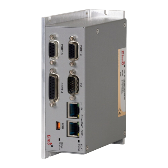
- Page 1 Gold DC Trombone Digital Servo Drive Installation Guide EtherCAT and CAN July 2019 (Ver. 1.906) www.elmomc.com...
- Page 2 This guide contains proprietary information belonging to Elmo Motion Control Ltd. Such • information is supplied solely for the purpose of assisting users of the Gold DC Trombone servo drive in its installation. The text and graphics included in this manual are for the purpose of illustration and reference •...
- Page 3 Installation ....................13 Unpacking the Drive Components ................13 Connector Types ....................... 14 5.2.1 Mating Connector Types ................16 Mounting the Gold DC Trombone ................17 Connection Diagrams ....................18 5.4.1 Connection Diagrams for EtherCAT Version..........19 5.4.2 Connection Diagrams for CAN Version ............21 Chapter 6: Wiring .......................
- Page 4 CAN Communications Version ................. 65 6.12.1 CAN Wiring ....................66 6.13 Heat Dissipation ....................... 67 6.13.1 Gold DC Trombone Thermal Data ............. 67 6.13.2 Heat Dissipation Data ................67 6.13.3 How to Use the Charts ................68 Chapter 7: Powering Up ..................... 69 Initializing the System ....................
- Page 5 Chapter 2: Safety I nform ation In order to achieve the optimum, safe operation of the Gold DC Trombone, it is imperative that you implement the safety procedures included in this installation guide. This information is provided to protect you and to keep your work area safe when operating the Gold DC Trombone and accompanying equipment.
- Page 6 Make sure that the Safe Torque Off is operational CE Marking Conformance The Gold DC Trombone is intended for incorporation in a machine or end product. The actual end product must comply with all safety aspects of the relevant requirements of the European Safety of...
- Page 7 If backup functionality is required to store control parameters in the event of a mains power outage, then an A, H, S, or T optional Gold DC Trombone should be used, with an external 24 VDC isolated supply connected to it.
- Page 8 Gold DC Trombone Installation Guide MAN-G-DCTROIG-EC (Ver. 1.906) Chapter 4: Technical I nform ation Physical Specifications Feature Units All Types Weight g (oz) 650 g (22.9 oz) for standard L shape 1100 g (38.8 oz) for L shape fins and fan...
- Page 9 24 V control supply. If there is a 0 or 1 Option, the control power supply operates from the main power. Note on current ratings: The current ratings of the Gold DC Trombone are given in units of DC amperes (ratings that are used for trapezoidal commutation or DC motors). The RMS (sinusoidal commutation) value is the DC value divided by 1.41.
- Page 10 Gold DC Trombone Installation Guide MAN-G-DCTROIG-EC (Ver. 1.906) Auxiliary Supply Feature Details Auxiliary power supply Isolated DC source only Auxiliary supply input voltage 18 VDC to 30 VDC Auxiliary supply input power Product Features Main Feature Details Presence and No.
- Page 11 Gold DC Trombone Installation Guide MAN-G-DCTROIG-EC (Ver. 1.906) Environmental Conditions You can guarantee the safe operation of the Gold DC Trombone by ensuring that it is installed in an appropriate environment. 4.6.1 Gold Line Feature Details Operating ambient temperature 0 °C to 40 °C (32 °F to 104 °F)
- Page 12 Gold DC Trombone Installation Guide MAN-G-DCTROIG-EC (Ver. 1.906) Gold Line Standards The following table describes the Main Standards of the Gold DC Trombone servo drive. For further details refer to the MAN-G-Panel Mounted Drives Hardware manual. Main Standards Item The related standards below apply to the performance of the servo drives as stated in the environmental conditions in section 4.6.1 Gold Line above.
- Page 13 The Gold DC Trombone must be installed in a suitable environment and properly connected to its voltage supplies and the motor. Unpacking the Drive Components Before you begin working with the Gold DC Trombone, verify that you have all of its components, as follows: •...
- Page 14 Gold DC Trombone Installation Guide MAN-G-DCTROIG-EC (Ver. 1.906) Connector Types The Gold DC Trombone has the following ten connectors. Pins Type Function Bottom Connectors 5.08 mm Phoenix high current 24 V 7.62 mm Phoenix high current Motor Connector 7.62 mm Phoenix high current...
- Page 15 Gold DC Trombone Installation Guide MAN-G-DCTROIG-EC (Ver. 1.906) Pins Type Function Front Connectors Front Connectors - EtherCAT Front Connectors - CAN ||Connector Types|www.elmomc.com Table of Contents...
- Page 16 EtherCAT OUT communication CAN Version RJ-45 RJ-45 Table 1: Connector Types The pinouts in Chapter 6: Wiring describe the function of each pin in the Gold DC Trombone connectors that are listed in Table 1. 5.2.1 Mating Connector Types Mating Pin Connector...
- Page 17 M4 round head screws, one through each opening in the heat sink, are used to mount the Gold DC Trombone (see the diagram below). Figure 2: Mounting the Gold DC Trombone with standard L-shape heat-sink Figure 3: Mounting the Gold DC Trombone with L-shape heat-sink fins and fan ||Mounting the Gold DC Trombone|www.elmomc.com...
- Page 18 Gold DC Trombone Installation Guide MAN-G-DCTROIG-EC (Ver. 1.906) Connection Diagrams There are two connection diagrams for EtherCAT and two for CAN that show the two different ways of connecting the power supply: 400 V and 800 V A, H, S, or T options (the catalog number has an A, H, S, or T option) that •...
- Page 19 Gold DC Trombone Installation Guide MAN-G-DCTROIG-EC (Ver. 1.906) 5.4.1 Connection Diagrams for EtherCAT Version The following describes the connection diagrams for the EtherCAT version. Figure 4: Gold DC Trombone EtherCAT Connection Diagram – with Backup Functionality (A, H, S, or T options) ||Connection Diagrams|www.elmomc.com...
- Page 20 Gold DC Trombone Installation Guide MAN-G-DCTROIG-EC (Ver. 1.906) Figure 5: Gold DC Trombone EtherCAT Connection Diagram – 400 V without Backup Functionality for Model Drives with 0 or 1 Options ||Connection Diagrams|www.elmomc.com Table of Contents...
- Page 21 Gold DC Trombone Installation Guide MAN-G-DCTROIG-EC (Ver. 1.906) 5.4.2 Connection Diagrams for CAN Version The following describes the connection diagrams for the CAN version. Figure 6: Gold DC Trombone Connection Diagram – with Backup Functionality (A, H, S, or T options) ||Connection Diagrams|www.elmomc.com...
- Page 22 Gold DC Trombone Installation Guide MAN-G-DCTROIG-EC (Ver. 1.906) Figure 7: Gold DC Trombone Connection Diagram – 400 V without Backup Functionality for Model Drives with 0 or 1 Options ||Connection Diagrams|www.elmomc.com Table of Contents...
- Page 23 Gold DC Trombone Installation Guide MAN-G-DCTROIG-EC (Ver. 1.906) Chapter 6: W iring Once the product is mounted, you are ready to wire the device. Proper wiring, grounding and shielding are essential for ensuring safe, immune and optimal servo performance of the drive.
- Page 24 Gold DC Trombone Installation Guide MAN-G-DCTROIG-EC (Ver. 1.906) Wiring Symbol Description D-type Connector: The cable`s braid (Shield) must be connected to the D-sub shell (metal housing) Encoder Earthing. T The cable`s shield is connected to the chassis (PE) in the connector.
- Page 25 Gold DC Trombone Installation Guide MAN-G-DCTROIG-EC (Ver. 1.906) Basic Recommendations 6.1.1 General Use shielded cables. For best results, the cable should have an aluminum foil shield covered by copper braid, and should contain a drain wire. Use 24, 26 or 28 AWG twisted-pair shielded with drain wire cables.
- Page 26 Gold DC Trombone Installation Guide MAN-G-DCTROIG-EC (Ver. 1.906) 6.1.2 Feedback Cable Port A and Port B Connector On the motor side connections, ground the shield to the motor chassis. At least One COMRET (Common Return) must be connected to the PE.
- Page 27 Gold DC Trombone Installation Guide MAN-G-DCTROIG-EC (Ver. 1.906) 6.1.3 Feedback Cable Port C Connector At the controller side connections, follow the controller manufacturer’s recommendations concerning the shield. The connection of the Drain wire to the Port C is not mandatory.
- Page 28 Gold DC Trombone Installation Guide MAN-G-DCTROIG-EC (Ver. 1.906) 6.1.5 STO (Port C) Cable Connector It is recommended to use shielded cable, but is not mandatory. Figure 12: STO Cable Assemblies ||Basic Recommendations|www.elmomc.com Table of Contents...
- Page 29 Gold DC Trombone Installation Guide MAN-G-DCTROIG-EC (Ver. 1.906) Motor Power Connector Pinouts See Chapter 8 in the in the MAN-G-Panel Mounted Drives Hardware manual for full details. Function Cable Brushless Motor Brushed DC Motor Motor phase Motor Motor Motor phase...
- Page 30 Gold DC Trombone Installation Guide MAN-G-DCTROIG-EC (Ver. 1.906) To power the drive, connect the M1, M2, M3, and PE pins on the Gold DC Trombone. The phase connection is arbitrary as Elmo Application Studio II (EAS II) will establish the proper commutation automatically during setup.
- Page 31 The following sections contain topology recommendations for implementing three-phase and a single-phase supply chains. The power stage of the Gold DC Trombone is fully isolated from the other sections of the Gold DC Trombone, such as the control-stage and the heat sink. This isolation allows the user to connect...
- Page 32 Gold DC Trombone Installation Guide MAN-G-DCTROIG-EC (Ver. 1.906) servo drive, the AC is limited to 528 VAC input (Phase to Phase), so as not to exceed the maximum 747 VDC (in the case of an 800 VDC drive). ||Main Power|www.elmomc.com...
- Page 33 Gold DC Trombone Installation Guide MAN-G-DCTROIG-EC (Ver. 1.906) 6.3.1 Direct-to-Mains Power Source This section relates to the configuration of the drive, which is connected directly to the mains. To connect the non-isolated AC power supply: 1. For best noise immunity, a shielded (not twisted) cable is recommended (not mandatory) for the DC input cable.
- Page 34 Gold DC Trombone Installation Guide MAN-G-DCTROIG-EC (Ver. 1.906) 6.3.1.2 Single-Phase Direct-to-Mains Connection Topology Figure 16: Non-Isolated Single-Phase Connection Topology The Power Supply is connected directly to the mains AC line. ||Main Power|www.elmomc.com Table of Contents...
- Page 35 Gold DC Trombone Installation Guide MAN-G-DCTROIG-EC (Ver. 1.906) 6.3.1.3 Multiple Connections Topology In a multi-axis application it is likely that a single power supply can feed several drives in parallel. The power supply is connected directly to the mains AC line and it feeds more than one drive.
- Page 36 Gold DC Trombone Installation Guide MAN-G-DCTROIG-EC (Ver. 1.906) 6.3.2 Battery Power Supply Figure 18: Battery Connection Topology Caution: When using batteries, it is recommended to connect the negative pole to the PE. When doing so, the charger of the battery must be isolated from the mains by an isolation transformer.
- Page 37 If backup functionality is required to store control parameters in the event of a mains power outage, then an A, H, S, or T options Gold DC Trombone should be used, with an external 24 VDC isolated supply connected to it.
- Page 38 Gold DC Trombone Installation Guide MAN-G-DCTROIG-EC (Ver. 1.906) Connect the auxiliary 24 VDC power supply as described below. To connect the 24 VDC backup supply: Use a 24 AWG twisted pair shielded cable. The shield should be braided. The source of the 24VDC backup supply must be isolated from the Mains.
- Page 39 Gold DC Trombone Installation Guide MAN-G-DCTROIG-EC (Ver. 1.906) Port A See Section 10.3 in the in the MAN-G-Panel Mounted Drives Hardware manual for full details. Incremental Encoder Absolute Serial Encoder Pin on Signal Function Signal Function Port A 12,4 Encoder +5V supply...
- Page 40 Gold DC Trombone Installation Guide MAN-G-DCTROIG-EC (Ver. 1.906) 6.5.1 Incremental Encoder The following figure describes the connections at Port A for the Incremental encoder. Figure 20: Port A D-Type Incremental Encoder Input – Recommended Connection Diagram 6.5.2 Hall Sensor The following figure describes the connections at Port A for the Hall Sensor.
- Page 41 Gold DC Trombone Installation Guide MAN-G-DCTROIG-EC (Ver. 1.906) 6.5.3 Absolute Serial Type Encoder The following figures describe the connections at Port A for the Absolute Serial type encoders. Figure 22: Absolute Serial Encoder – Recommended D-Type Connection Diagram for EnDAT, Biss, and SSI Figure 23: Absolute Serial Encoder –...
- Page 42 Gold DC Trombone Installation Guide MAN-G-DCTROIG-EC (Ver. 1.906) Figure 24: Absolute Serial Encoder – Recommended D-Type Connection Diagram for Stegmann Hiperface ||Port A|www.elmomc.com Table of Contents...
- Page 43 Gold DC Trombone Installation Guide MAN-G-DCTROIG-EC (Ver. 1.906) Port B See Section 10.4 in the in the MAN-G-Panel Mounted Drives Hardware manual for full details. Incremental or Resolver Interpolated Analog Encoder G-DCTROXXX/YYYYXEXX G-DCTROXXX/YYYYXRXX Pin on Signal Function Signal Function Port B...
- Page 44 Gold DC Trombone Installation Guide MAN-G-DCTROIG-EC (Ver. 1.906) 6.6.1 Incremental Encoder The following figure describes the connections at Port B for the Incremental encoder. Figure 25: Port B Incremental Encoder Input – Recommended D-Type Connection Diagram ||Port B|www.elmomc.com Table of Contents...
- Page 45 Gold DC Trombone Installation Guide MAN-G-DCTROIG-EC (Ver. 1.906) 6.6.2 Interpolated Analog Encoder The following figure describes the connections at Port B for the Interpolated Analog encoder. Figure 26: Port B - Interpolated Analog Encoder D-Type Connection Diagram ||Port B|www.elmomc.com Table of Contents...
- Page 46 Gold DC Trombone Installation Guide MAN-G-DCTROIG-EC (Ver. 1.906) 6.6.3 Resolver The following figure describes the connections at Port B for the Resolver encoder. Figure 27: Port B – Resolver D-Type Connection Diagram ||Port B|www.elmomc.com Table of Contents...
- Page 47 Gold DC Trombone Installation Guide MAN-G-DCTROIG-EC (Ver. 1.906) Port C, Analog Input, and STO The Port C connector includes the following functions: Port C: Refer to Sections 10.5 in the in the MAN-G-Panel Mounted Drives Hardware manual • for full details •...
- Page 48 Gold DC Trombone Installation Guide MAN-G-DCTROIG-EC (Ver. 1.906) Pin Positions 15-Pin High Density 15-Socket High Density D-Type Connector D-Type Male Connector Table 7: Port C Feedback Out and STO Analog In ||Port C, Analog Input, and STO|www.elmomc.com Table of Contents...
- Page 49 Gold DC Trombone Installation Guide MAN-G-DCTROIG-EC (Ver. 1.906) 6.7.1 Port C The following figure describes the connections at Port C for the Emulated Encoder Differential. Figure 28: Emulated Encoder Differential Output – Recommended D-Type Connection Diagram 6.7.2 Analog Input The following circuit describes the internal interface of the Analog input.
- Page 50 Gold DC Trombone Installation Guide MAN-G-DCTROIG-EC (Ver. 1.906) 6.7.3 The following circuits describe the STO wiring options. 6.7.3.1 Source Mode PLC Voltage Level Figure 30: STO D-Type Input Connection – PLC Source Option 6.7.3.2 TTL Mode TTL Voltage Level Figure 31: STO Input Connection – TTL Option ||Port C, Analog Input, and STO|www.elmomc.com...
- Page 51 Gold DC Trombone Installation Guide MAN-G-DCTROIG-EC (Ver. 1.906) 6.7.3.3 SINK Mode – PLC Voltage Level Refer to the diagrams below for the PLC Sink option connections which is not fully certified for STO. This option is not recommended for new designs.
- Page 52 Gold DC Trombone Installation Guide MAN-G-DCTROIG-EC (Ver. 1.906) Digital Inputs and Outputs Refer to Chapter 11 in the in the MAN-G-Panel Mounted Drives Hardware manual for full details. Pin on I/O Signal Function Programmable digital input 1 Programmable digital input 2...
- Page 53 Gold DC Trombone Installation Guide MAN-G-DCTROIG-EC (Ver. 1.906) Pin Positions 15-Pin High Density 15-Pin High Density D-Type Male Connector D-Type Female Connector Table 8: I/O Connector Pin Assignments ||Digital Inputs and Outputs|www.elmomc.com Table of Contents...
- Page 54 Gold DC Trombone Installation Guide MAN-G-DCTROIG-EC (Ver. 1.906) 6.8.1 Digital Input and Output TTL Mode The following figure describes the connections at the I/O Port for the Digital Input and Output TTL Mode. Figure 33: Digital Input TTL Mode D-Type Connection Diagram ||Digital Inputs and Outputs|www.elmomc.com...
- Page 55 Gold DC Trombone Installation Guide MAN-G-DCTROIG-EC (Ver. 1.906) Figure 34: Digital Output D-Type Connection Diagram – TTL Option ||Digital Inputs and Outputs|www.elmomc.com Table of Contents...
- Page 56 Gold DC Trombone Installation Guide MAN-G-DCTROIG-EC (Ver. 1.906) 6.8.2 Digital Input and Output PLC Source Mode The following figure describes the connections at the I/O Port for the Digital Input and Output PLC Mode. Figure 35: Digital Input D-Type Connection Diagram – Source PLC Option ||Digital Inputs and Outputs|www.elmomc.com...
- Page 57 Gold DC Trombone Installation Guide MAN-G-DCTROIG-EC (Ver. 1.906) Figure 36: Digital Output D-Type Connection Diagram – Source PLC Option ||Digital Inputs and Outputs|www.elmomc.com Table of Contents...
- Page 58 Gold DC Trombone Installation Guide MAN-G-DCTROIG-EC (Ver. 1.906) 6.8.3 Digital Input and Output Sink Mode The following figure describes the connections at the I/O Port for the Digital Input and Output Sink Mode. Figure 37: Digital Input Sink Mode – PLC voltage level D-Type Connection Diagram ||Digital Inputs and Outputs|www.elmomc.com...
- Page 59 Gold DC Trombone Installation Guide MAN-G-DCTROIG-EC (Ver. 1.906) Figure 38: Digital Output as Sink Configuration D-Type Connection Diagram ||Digital Inputs and Outputs|www.elmomc.com Table of Contents...
- Page 60 Gold DC Trombone Installation Guide MAN-G-DCTROIG-EC (Ver. 1.906) USB 2.0 See Section 12.1 in the in the MAN-G-Panel Mounted Drives Hardware manual for full details. Pin on USB Signal Function USB VBUS USB VBUS 5V USBD- USB _N line USBD+...
- Page 61 MAN-G-DCTROIG-EC (Ver. 1.906) 6.10 Drive Status Indicator The Gold DC Trombone is equipped with several light-emitting diode (LED) indicators. The red/green dual LED is used for immediate indication of the following states: Initiation state: In this state the LED indicates whether the drive is in the boot state (blinking •...
- Page 62 MAN-G-DCTROIG-EC (Ver. 1.906) 6.11 EtherCAT Communications Version Fieldbus communications are industrial network protocols for real-time distributed control that allows connection of servo drives. The Gold DC Trombone supports the following EtherCAT fieldbus type industrial network protocol: Fieldbus Type Product Number...
- Page 63 Gold DC Trombone Installation Guide MAN-G-DCTROIG-EC (Ver. 1.906) 6.11.2 EtherCAT OUT Pinouts See Section 12.2 in the MAN-G-Panel Mounted Drives Hardware manual for the electrical diagram. Signal Function EtherCAT_OUT_TX+ EtherCAT out transmit + EtherCAT_OUT_TX- EtherCAT out transmit - EtherCAT_OUT_RX+ EtherCAT out receive +...
- Page 64 This section is only relevant for EtherCAT (P/N G-DCTRO XX/YYYEXXX) products only. The Gold DC Trombone can serve as an EtherCAT slave device. For this purpose it has two RJ-45 connectors, which are designated as EtherCAT In and EtherCAT Out. Each of these RJ-45 connectors has two status LEDs, which are shown in Figure 41.
- Page 65 MAN-G-DCTROIG-EC (Ver. 1.906) 6.12 CAN Communications Version Fieldbus communications are industrial network protocols for real-time distributed control that allows connection of servo drives. The Gold DC Trombone supports the following CAN fieldbus type industrial network protocol. Fieldbus Type Product Number G-DCTRO XX/YYYSXXX See Section 12.4 in the MAN-G-Panel Mounted Drives Hardware manual for the electrical diagram.
- Page 66 Figure 42 describes the CAN wiring diagram below. Caution When installing the CAN communications, ensure that each servo drive is allocated a unique ID. Otherwise, the CAN network may hang. Figure 42: Gold DC Trombone Connection Diagram – CAN ||CAN Communications Version|www.elmomc.com Table of Contents...
- Page 67 MAN-G-DCTROIG-EC (Ver. 1.906) 6.13 Heat Dissipation The best way to dissipate heat from the Gold DC Trombone is to mount it so that its heatsink faces up. For best results leave approximately 10 mm of space between the Gold DC Trombone‘s heat sink and any other assembly.
- Page 68 Allow maximum heat sink temperature to be 80 °C or less (shunt down is 6 °C to 8 °C higher). Determine the ambient operating temperature of the Gold DC Trombone as ≤ 40 °C. Calculate the allowable temperature increase according to the following example: For an ambient temperature of 40 °C, ΔT = 80 to 40°C = 40°C...
- Page 69 MAN-G-DCTROIG-EC (Ver. 1.906) Chapter 7: Pow ering Up After the Gold DC Trombone is connected to its device, it is ready to be powered up. Caution: Before applying power, ensure that the DC supply is within the specified range and that the proper plus-minus connections are in order.
- Page 70 Gold DC Trombone Installation Guide MAN-G-DCTROIG-EC (Ver. 1.906) Chapter 8: Gold DC Trom bone Dim ensions This chapter provides detailed technical information regarding the Gold DC Trombone. Figure 45: Gold DC Trombone Dimensions with standard L-shape heat-sink ||Initializing the System|www.elmomc.com...
- Page 71 Gold DC Trombone Installation Guide MAN-G-DCTROIG-EC (Ver. 1.906) Figure 46: Gold DC Trombone Dimensions with L-shape heat-sink fins and fan ||Initializing the System|www.elmomc.com Table of Contents...
- Page 72 ||www.elmomc.com Table of Contents...
Need help?
Do you have a question about the Gold DC Trombone and is the answer not in the manual?
Questions and answers