
Subscribe to Our Youtube Channel
Related Manuals for Elmo SimpliQ Line


Summary of Contents for Elmo SimpliQ Line
- Page 1 sales@artisantg.com artisantg.com (217) 352-9330 | Visit our website - Click HERE...
- Page 2 DC Trombone Digital Servo Drive Installation Guide October 2017 (Ver. 1.602) www.elmomc.com...
- Page 3 This guide is delivered subject to the following conditions and restrictions: • This guide contains proprietary information belonging to Elmo Motion Control Ltd. Such information is supplied solely for the purpose of assisting users of the DC Trombone servo drive in its installation.
- Page 4 “Metronome” was replaced by the “Composer” software. Ver. 1.401 February 2013 Added a caution and recommendation on the type of cleaning solution to use for the Elmo unit. Ver. 1.500 May 2013 Addition of heat-sink option to lower side of the drive.
- Page 5 Germany Tel: +49 (0) 7721-944 7120 • Fax: +49 (0) 7721-944 7130 • info-de@elmomc.com China Elmo Motion Control Technology (Shanghai) Co. Ltd. Room 1414, Huawen Plaza, No. 999 Zhongshan West Road, Shanghai (200051) China Tel: +86-21-32516651 • Fax: +86-21-32516652 •...
-
Page 6: Table Of Contents
DC Trombone Installation Guide MAN-DCTROIG (Ver. 1.602) Table of Contents Chapter 1: Safety Information ..................8 1.1. Warnings ......................... 9 1.2. Cautions .......................... 9 1.3. Directives and Standards ....................10 1.4. CE Marking Conformance ..................... 10 1.5. Warranty Information ....................10 Chapter 2: Product Description .................. - Page 7 Table of Contents DC Trombone Installation Guide MAN-DCTROIG (Ver. 1.602) 3.6.6. Battery Power Supply ..................33 3.6.7. Connecting the Control and Backup Supply (24 V) ........33 3.7. Feedback and Control Cable Assemblies ..............35 3.7.1. Main Feedback Cable (FEEDBACK A) ............. 35 3.7.2.
- Page 8 Table of Contents DC Trombone Installation Guide MAN-DCTROIG (Ver. 1.602) 4.7. Feedbacks ........................75 4.7.1. Feedback Supply Voltage ................75 4.7.2. Main Feedback Options ................. 75 4.7.2.1. Incremental Encoder Input ............75 4.7.2.2. Digital Halls ................... 76 4.7.2.3. Absolute Encoder ................76 4.7.2.4.
-
Page 9: Chapter 1: Safety Information
DC Trombone Installation Guide MAN-DCTROIG (Ver. 1.602) Chapter 1: Safety I nform ation In order to operate the DC Trombone servo drive safely, it is imperative that you implement the safety procedures included in this installation guide. This information is provided to protect you and to keep your work area safe when operating the DC Trombone and accompanying equipment. -
Page 10: Warnings
7 (8 to 14). The solvent corrodes the plastic cover causing cracks and eventual damage to the drive's PCBs. Elmo recommends using the cleaning fluid Vigon-EFM which is pH Neutral (7). For further technical information on this recommended cleaning fluid, select the link: http://www.zestron.com/fileadmin/zestron.com-usa/daten/electronics/Product_TI1s/TI1-... -
Page 11: Directives And Standards
All Elmo drives are warranted for a period of 12 months from the date of shipment. No other warranties, expressed or implied — and including a warranty of merchantability and fitness for a particular purpose —... -
Page 12: Chapter 2: Product Description
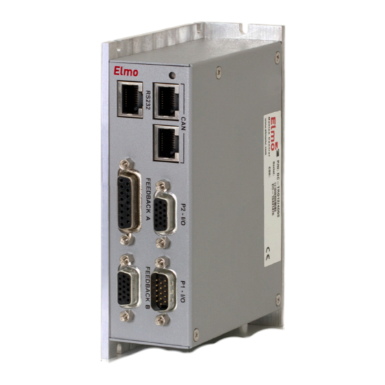
The DC Trombone, as part of the SimplIQ product line, is fully programmable with Elmo’s Composer motion control language. Power to the drives is provided by a DC power source (not included with the DC Trombone). Elmo recommends using the Elmo Tambourine Power Supply, which is ideally suited to the Trombone, DC Trombone, and Solo Trombone. -
Page 13: Product Features
Product Description DC Trombone Installation Guide MAN-DCTROIG (Ver. 1.602) • The Advanced DC Trombone includes all the motion capabilities and communication options included in the Standard model, as well as advanced positioning capabilities: ECAM, Dual Loop and increased program size. (The catalog number starts DC-TROA.) Both versions operate with RS-232 and CAN communication. -
Page 14: Advanced Position Control
Up to 512 revolutions per second (RPS) Auxiliary emulated, unbuffered, single-ended, encoder output • Tachometer, Potentiometer • Absolute Encoder Heidenhain 2.1 Heidenhain 2.2 Panasonic Stegmann Note: Elmo drives provide supply voltage for all the feedback options. www.elmomc.com... -
Page 15: Fault Protection
Product Description DC Trombone Installation Guide MAN-DCTROIG (Ver. 1.602) 2.2.7. Fault Protection The DC Trombone includes built-in protection against possible fault conditions, including: • Software error handling • Status reporting for a large number of possible fault conditions • Protection against conditions such as excessive temperature, under/over voltage, loss of commutation signal, short circuits between the motor power outputs and between each output and power input/return •... -
Page 16: How To Use This Guide
In order to install and operate the DC Trombone servo drive, you will use this manual in conjunction with a set of Elmo documentation. Installation is your first step; after carefully reading the safety instructions in the first chapter, the following chapters provide you with installation instructions as follows: •... -
Page 17: Chapter 3: Installation
DC Trombone Installation Guide MAN-DCTROIG (Ver. 1.602) Chapter 3: I nstallation 3.1. Before You Begin 3.1.1. Site Requirements You can guarantee the safe operation of the DC Trombone by ensuring that it is installed in an appropriate environment. Feature Value Ambient operating temperature 0 °C to 40 °C (32 °F to 104 °F) Maximum Operating Altitude... -
Page 18: Hardware Requirements
Installation DC Trombone Installation Guide MAN-DCTROIG (Ver. 1.602) 3.1.2. Hardware Requirements The components that you will need to install your DC Trombone are: Component Connector Described Diagram in Section Main Power Cable PE VN- VP+ 3.6.4 Motor Cable M3 M2 M1 PE 3.6.3 VL+ VL- Backup Supply Cable... - Page 19 Installation DC Trombone Installation Guide MAN-DCTROIG (Ver. 1.602) Component Connector Described Diagram in Section Digital I/O Cable GENERAL I/O 3.8.1 (if needed) Digital Inputs and GENERAL I/O 3.8.1.2 Analog Inputs Cable (if needed) RS232 RS232 Communication 3.9.1.1 Cable CAN Communication CAN (in) 3.9.1.2 cable(s) (if needed)
-
Page 20: Unpacking The Drive Components
Installation DC Trombone Installation Guide MAN-DCTROIG (Ver. 1.602) 3.2. Unpacking the Drive Components Before you begin working with the DC Trombone system, verify that you have all of its components, as follows: • The DC Trombone servo drive • The Composer software and software manual The DC Trombone is shipped in a cardboard box with Styrofoam protection. -
Page 21: Connectors
Installation DC Trombone Installation Guide MAN-DCTROIG (Ver. 1.602) 3.3. Connectors 3.3.1. Connector Types The DC Trombone has the following connectors: Bottom Connectors Pins Type Function Connector for optional backup supply in S type 5.08 mm Phoenix high current drives Motor Connector 7.62 mm Phoenix high current Power Connector 7.62 mm Phoenix high current... -
Page 22: Mounting The Dc Trombone
Installation DC Trombone Installation Guide MAN-DCTROIG (Ver. 1.602) 3.4. Mounting the DC Trombone The DC Trombone has been designed for two standard mounting options: • Wall Mount along the back (can also be mounted horizontally on a metal surface) • Book Shelf along the side M4 round head screws, one through each opening in the heat sink, are used to mount the DC Trombone (see the diagram below). - Page 23 Installation DC Trombone Installation Guide MAN-DCTROIG (Ver. 1.602) Figure 3: Mounting the DC Trombone with Heat-Sink Fan and Fins www.elmomc.com...
-
Page 24: Connections
Installation DC Trombone Installation Guide MAN-DCTROIG (Ver. 1.602) 3.5. Connections 3.5.1. Wiring the DC Trombone Once the DC Trombone is mounted, you are ready to wire the device. Proper wiring, grounding and shielding are essential for ensuring safe, immune and optimal servo performance of the DC Trombone. -
Page 25: Connection Diagrams
Installation DC Trombone Installation Guide MAN-DCTROIG (Ver. 1.602) 3.5.2. Connection Diagrams The following two connection diagrams (Figure 4, Figure 5) show the three different ways of connecting the servo drive: • 400 V and 800 V S models (the catalog number has an S option) that feature backup functionality and require an auxiliary 24 V backup supply. - Page 26 Installation DC Trombone Installation Guide MAN-DCTROIG (Ver. 1.602) Figure 4: DC Trombone Connection Diagram – with Backup Functionality (S Type Drive) www.elmomc.com...
- Page 27 Installation DC Trombone Installation Guide MAN-DCTROIG (Ver. 1.602) Figure 5: DC-DC Trombone Connection Diagram – 400 V without Backup Functionality www.elmomc.com...
-
Page 28: Connecting The Power Cables
Installation DC Trombone Installation Guide MAN-DCTROIG (Ver. 1.602) 3.6. Connecting the Power Cables The power connectors are located at the bottom of the DC Trombone, as follows: 3.6.1. For S type drives Function Cable Power Positive Power input DC Power Negative Power input DC Power Protective earth... -
Page 29: For Non-S 400 Vdc Type Drives
Installation DC Trombone Installation Guide MAN-DCTROIG (Ver. 1.602) 3.6.2. For Non-S 400 VDC Type Drives Function Cable Power Positive Power input DC Power Negative Power input DC Power Protective earth DC Power Motor Protective earth Motor Motor Motor phase Motor Motor phase Motor Motor... -
Page 30: Connecting The Motor Cable
The DC power to the DC Trombone is delivered from a separated rectifying-unit (supplied by the user). The following sections contain topology recommendations for implementing three- phase and a single-phase supply chains. Elmo offers the end-user, the option to purchase its Tambourine rectifier, which offers a range of versatile options. -
Page 31: Direct-To-Mains Power Source (Non-Isolated Rectifier)
390 VDC in the case of a 400 VDC drive, or 528 VAC so as not to exceed the maximum 747 VDC in the case of an 800 VDC drive. If the Trombone is connected to Elmo’s Tambourine power supply, then the end-user can exploit the Tambourine’s options, such as EMI-filtering and shunt-regulator. -
Page 32: Single-Phase Direct-To-Mains Connection Topology
Installation DC Trombone Installation Guide MAN-DCTROIG (Ver. 1.602) 3.6.5.2. Single-Phase Direct-to-Mains Connection Topology Figure 8: Non-Isolated Single-Phase Connection Topology The Power Supply is connected directly to the Mains AC line. Warning: Do not connect VN- to PE. In a direct-to-mains connection the VN- must not be connected to the PE, as this will cause irreparable damage to the system. -
Page 33: Multiple Connections Topology
Installation DC Trombone Installation Guide MAN-DCTROIG (Ver. 1.602) 3.6.5.3. Multiple Connections Topology When applied in a multi-axis arrangement, it is likely that a single power supply can feed several drives in parallel. This topology is efficient and cost saving, reducing the number of power supplies and the amount of wiring. -
Page 34: Battery Power Supply
Installation DC Trombone Installation Guide MAN-DCTROIG (Ver. 1.602) 3.6.6. Battery Power Supply Figure 10: Battery Connection Topology Caution: When using batteries, it is recommended to connect the negative pole to the must When doing so, the charger of the battery be isolated from the mains by an isolation transformer. - Page 35 Installation DC Trombone Installation Guide MAN-DCTROIG (Ver. 1.602) Figure 11: Auxiliary 24 VDC Backup Supply Connection Diagram Signal Function Cable +24VDC +24 VDC backup supply Input Positive 24VDC RET Return (common) of the 24 VDC backup supply 2-Pin Phoenix Plug-in Connector Table 4: Backup Cable Plug www.elmomc.com...
-
Page 36: Feedback And Control Cable Assemblies
Installation DC Trombone Installation Guide MAN-DCTROIG (Ver. 1.602) 3.7. Feedback and Control Cable Assemblies The DC Trombone features easy-to-use D-Sub type connections for all Control and Feedback cables. Below are instructions and diagrams describing how to assemble those cables. 1. Use 24, 26 or 28 AWG twisted-pair shielded cables (24 AWG cable is recommended). For best results, the shield should have aluminum foil covered by copper braid. - Page 37 Installation DC Trombone Installation Guide MAN-DCTROIG (Ver. 1.602) FEEDBACK A on the “front” of the DC Trombone has a 15-pin D-Sub socket. Connect the Main Feedback cable from the motor to FEEDBACK A using a 15-pin, D-Sub plug with a metal housing. When assembling the Main Feedback cable, follow the instructions in Section 3.7 (Feedback and Control Cable Assemblies).
- Page 38 Installation DC Trombone Installation Guide MAN-DCTROIG (Ver. 1.602) Absolute Encoders DC-TROXX/YYYQ DC-TROXX/YYYP Signal Heidenhain Stegmann Panasonic Hall C Hall C Hall C Hall A Hall A Hall A SUPRET Supply return Supply return Supply return EnDat (Heidenhain) Encoder Halls supply +5V Encoder +5V supply +5V supply Sine A complement...
- Page 39 Installation DC Trombone Installation Guide MAN-DCTROIG (Ver. 1.602) Figure 13: Main Feedback- Incremental Encoder Connection Diagram www.elmomc.com...
- Page 40 Installation DC Trombone Installation Guide MAN-DCTROIG (Ver. 1.602) Figure 14: Main Feedback – Interpolated Analog Encoder Connection Diagram Figure 15: Main Feedback – Resolver Connection Diagram www.elmomc.com...
- Page 41 Installation DC Trombone Installation Guide MAN-DCTROIG (Ver. 1.602) Figure 16: Main Feedback – Tachometer Feedback with Digital Hall Sensor Connection Diagram for Brushless Motors Figure 17: Main Feedback – Tachometer Feedback Connection Diagram for Brush Motors www.elmomc.com...
- Page 42 Installation DC Trombone Installation Guide MAN-DCTROIG (Ver. 1.602) Figure 18: Main Feedback – Potentiometer Feedback with Digital Hall Sensor Connection Diagram for Brushless Motors Figure 19: Main Feedback – Potentiometer Feedback Connection Diagram for Brush Motors and Voice Coils www.elmomc.com...
- Page 43 Installation DC Trombone Installation Guide MAN-DCTROIG (Ver. 1.602) Figure 20: Main Feedback – Stegmann Feedback Connection Diagram www.elmomc.com...
- Page 44 Installation DC Trombone Installation Guide MAN-DCTROIG (Ver. 1.602) Figure 21: Main Feedback – Heidenhain Feedback Connection Diagram www.elmomc.com...
-
Page 45: Main And Auxiliary Feedback Combinations
Installation DC Trombone Installation Guide MAN-DCTROIG (Ver. 1.602) 3.7.2. Main and Auxiliary Feedback Combinations The Main Feedback is always used in motion control devices, whereas the Auxiliary Feedback is often, but not always used. The Auxiliary Feedback connector on the DC Trombone, FEEDBACK B, has two ports, Port B1 and Port B2. - Page 46 Installation DC Trombone Installation Guide MAN-DCTROIG (Ver. 1.602) MAIN AUX. FEEDBACK Ports B1 and B2 FEEDBACK YA[4] = 4 Software Setting Incremental Encoder Input Feedback A (Main Feedback): Digital Encoder Main Buffered Output via P2: Differential and buffered main Feedback B (Auxiliary Feedback) encoder signals B1 Input: Feedback B (Auxiliary Feedback)
- Page 47 Installation DC Trombone Installation Guide MAN-DCTROIG (Ver. 1.602) MAIN AUX. FEEDBACK Ports B1 and B2 FEEDBACK YA[4] = 2 Software Setting Incremental Encoder Input Feedback A (Main Feedback): Digital Encoder Main Buffered Output via P2: Differential and buffered main Feedback B (Auxiliary Feedback) encoder signals B1 Input: Differential Incremental Encoder...
- Page 48 Installation DC Trombone Installation Guide MAN-DCTROIG (Ver. 1.602) AUX. FEEDBACK Ports B1 and B2 MAIN FEEDBACK YA[4] = 0 Software Setting Incremental Encoder Input Feedback A (Main Feedback): Digital Encoder Main Buffered Output via P2: Differential and buffered main Feedback B (Auxiliary Feedback) encoder signals B1 Input: Pulse and Direction signals...
-
Page 49: Feedback B (Auxiliary Feedback)
Installation DC Trombone Installation Guide MAN-DCTROIG (Ver. 1.602) 3.7.3. FEEDBACK B (Auxiliary Feedback) When using one of the auxiliary feedback options, the relevant functionality of the AUX. FEEDBACK ports are software selected for that option. Refer to the SimplIQ Command Reference Manual for detailed information about FEEDBACK B setup. - Page 50 Installation DC Trombone Installation Guide MAN-DCTROIG (Ver. 1.602) Below are the signals on the Auxiliary Feedback ports when set up to run as buffered emulated outputs of the following main encoders(on FEEDBACK A): • Interpolated Analog Encoder • Resolver • Tachometer and Potentiometer •...
- Page 51 Installation DC Trombone Installation Guide MAN-DCTROIG (Ver. 1.602) FEEDBACK B on the DC Trombone has a 15-pin high density D-Sub socket. Connect the Auxiliary Feedback cable, from the controller or other device, to FEEDBACK B using a 15-pin, high density D-Sub plug with a metal housing. When assembling the Auxiliary Feedback cable, follow the instructions in Section 3.7 (Feedback and Control Cable Assemblies).
-
Page 52: Differential Auxiliary Encoder Input Option On Feedback B (Ya[4]=2)
Installation DC Trombone Installation Guide MAN-DCTROIG (Ver. 1.602) 3.7.3.2. Differential Auxiliary Encoder Input Option on FEEDBACK B (YA[4]=2) The DC Trombone can be used as a slave by receiving the position of the master encoder data (on Port B1) in Follower or ECAM mode. In this mode Port B2 provides differential buffered auxiliary outputs of Port B1 for the next slave axis in follower or ECAM mode. - Page 53 Installation DC Trombone Installation Guide MAN-DCTROIG (Ver. 1.602) FEEDBACK B on the DC Trombone has a 15-pin high density D-Sub socket. Connect the Auxiliary Feedback cable from the feedback device to FEEDBACK B using a 15-pin, high density D-Sub plug with a metal housing. When assembling the Auxiliary Feedback cable, follow the instructions in Section 3.7 (Feedback and Control Cable Assemblies).
-
Page 54: Differential Pulse-And-Direction Input Option On Feedback B (Ya[4]=0)
Installation DC Trombone Installation Guide MAN-DCTROIG (Ver. 1.602) 3.7.3.3. Differential Pulse-and-Direction Input Option on FEEDBACK B (YA[4]=0) This mode is used for input of differential pulse-and-direction position commands on Port B1. In this mode Port B2 provides differential buffered pulse-and-direction outputs of Port B1 for another axis. - Page 55 Installation DC Trombone Installation Guide MAN-DCTROIG (Ver. 1.602) Figure 24: Differential Pulse-and-Direction Input Option on FEEDBACK B - Connection Diagram www.elmomc.com...
-
Page 56: I/O Cables
Installation DC Trombone Installation Guide MAN-DCTROIG (Ver. 1.602) 3.8. I/O Cables The DC Trombone has two I/O ports, P1 and P2. P1 is a general I/O which can be used to connect 6 digital inputs and 4 digital outputs. P2 has 1 analog input port, and buffered encoder signals that are derived from the main feedback: P1 Port P2 Port... -
Page 57: Digital Output (As Source Configuration) & Input (As Sink Configuration)
Installation DC Trombone Installation Guide MAN-DCTROIG (Ver. 1.602) 3.8.1.1. Digital Output (as Source Configuration) & Input (as Sink Configuration) Signal Function Pin Positions Programmable input 1 Programmable input 2 OUT1 Programmable output 1 up to 0.5 A OUT2 Programmable output 2 up to 0.5 A OUT3 Programmable output 3 up to 0.5 A INRET... - Page 58 Installation DC Trombone Installation Guide MAN-DCTROIG (Ver. 1.602) Figure 25: Digital Output (as Source Configuration) & Input (as Sink Configuration) P1 - Connection Diagram www.elmomc.com...
-
Page 59: Digital Output (As Sink Configuration) & Input (As Source Configuration)
Installation DC Trombone Installation Guide MAN-DCTROIG (Ver. 1.602) 3.8.1.2. Digital Output (as Sink Configuration) & Input (as Source Configuration) Signal Function Pin Positions Programmable input 1 return Programmable input 2 return OUT1 Programmable output 1 up to 50 mA OUT2 Programmable output 2 up to 50 mA OUT3 Programmable output 3 up to 50 mA... - Page 60 Installation DC Trombone Installation Guide MAN-DCTROIG (Ver. 1.602) Figure 26: Digital Output (as Sink Configuration) & Input (as Source Configuration) P1 - Connection Diagram www.elmomc.com...
-
Page 61: General I/O Port (P2)
Installation DC Trombone Installation Guide MAN-DCTROIG (Ver. 1.602) 3.8.2. General I/O Port (P2) Port P2 has a 15-pin high density D-Sub socket. When assembling this I/O cable, follow the instructions in Section 3.7 (Feedback and Control Cable Assemblies) using a 15-pin high density metal case D-Sub male connector (plug). - Page 62 Installation DC Trombone Installation Guide MAN-DCTROIG (Ver. 1.602) Figure 27: General I/O P2 - Connection Diagram www.elmomc.com...
-
Page 63: Communication Cables
Installation DC Trombone Installation Guide MAN-DCTROIG (Ver. 1.602) 3.9. Communication Cables The communication cables use an 8-pin RJ-45 plug that connect to the RS-232 and CAN ports of the DC Trombone. The communication interface may differ according to the user’s hardware. The DC Trombone can communicate using the following options: a. -
Page 64: Can Communication
Installation DC Trombone Installation Guide MAN-DCTROIG (Ver. 1.602) Figure 28: RS-232 Connection Diagram 3.9.1.2. CAN Communication Notes for connecting the CAN communication cable: • Use 26 or 28 AWG twisted pair shielded cables. For best results, the shield should have aluminum foil and covered by copper braid with a drain wire •... - Page 65 Installation DC Trombone Installation Guide MAN-DCTROIG (Ver. 1.602) Caution: When installing the CAN communications, ensure that each servo drive is allocated a unique ID. Otherwise, the CAN network may hang. Figure 29: CAN - Connection Diagram www.elmomc.com...
-
Page 66: 3.10. Powering Up
3.11. Initializing the System After the DC Trombone has been connected and mounted, the system must be set up and initialized. This is accomplished using the Composer, Elmo’s Windows-based software application. Install the application and then perform setup and initialization according to the directions in the Composer Software Manual. -
Page 67: Chapter 4: Technical Specifications
DC Trombone Installation Guide MAN-DCTROIG (Ver. 1.602) Chapter 4: Technical Specifications 4.1. Features 4.1.1. Motion Control Modes • Current/Torque - up to 14 kHz sampling rate • Velocity - up to 7 kHz sampling rate • Position - up to 3.5 kHz sampling rate 4.1.2. -
Page 68: Input/Output
Technical Specifications DC Trombone Installation Guide MAN-DCTROIG (Ver. 1.602) • Interpolated Analog Sine/Cosine Encoder – up to 250 kHz (analog signal) Internal Interpolation - up to x4096 Automatic Correction of amplitude mismatch, phase mismatch, signal offset Emulated encoder outputs, differential, buffered of the Analog encoder ... -
Page 69: Built-In Protection
Technical Specifications DC Trombone Installation Guide MAN-DCTROIG (Ver. 1.602) 4.1.7. Built-In Protection • Software error handling • Abort (hard stops and soft stops) • Status reporting • Protection against: Shorts between motor power outputs Shorts between motor power outputs and power input/return ... -
Page 70: Dimensions
Technical Specifications DC Trombone Installation Guide MAN-DCTROIG (Ver. 1.602) 4.2. Dimensions Figure 30: DC Trombone with L-shaped Heat-Sink Figure 31: DC Trombone with Heat-Sink Fan and Fins www.elmomc.com... -
Page 71: Power Ratings For The 400 V Type
Technical Specifications DC Trombone Installation Guide MAN-DCTROIG (Ver. 1.602) 4.3. Power Ratings for the 400 V Type Feature Units 6/400 12/400 16/400 R17/400 R22/400 Minimum supply voltage S option in P/N: 50 No S option in P/N: 100 Nominal supply voltage Maximum supply voltage Maximum continuous power output... -
Page 72: Power Ratings For The 800 V Type
Technical Specifications DC Trombone Installation Guide MAN-DCTROIG (Ver. 1.602) Power Ratings for the 800 V Type 4.4. Feature Units 8/800 12/800 R11/800 R16/800 Minimum supply voltage S option in P/N: 95+ Nominal supply voltage 560 for 400 VAC 680 for 480 VAC Maximum supply voltage Maximum continuous power output... -
Page 73: Auxiliary Supply (Only For S Type Drive)
Technical Specifications DC Trombone Installation Guide MAN-DCTROIG (Ver. 1.602) 4.4.1. Auxiliary Supply (only for S Type Drive) Feature Details Isolated DC source only Auxiliary power supply Auxiliary supply input voltage 18 VDC to 30 VDC Auxiliary supply input power < 5 VA (this includes the 5 V/200 mA load for the main encoder only) <... -
Page 74: Control Specifications
Technical Specifications DC Trombone Installation Guide MAN-DCTROIG (Ver. 1.602) 4.6. Control Specifications 4.6.1. Current Loop Feature Details Controller type Vector, digital Compensation for bus voltage variations “On-the-fly” automatic gain scheduling Motor types • AC brushless (sinusoidal) • DC brushless (trapezoidal) •... -
Page 75: Velocity Loop
Technical Specifications DC Trombone Installation Guide MAN-DCTROIG (Ver. 1.602) 4.6.2. Velocity Loop Feature Details Controller type • Fully digital Velocity control • Programmable PI and FFW control filters • "On-the-fly" gain scheduling • Automatic, manual and advanced manual tuning • Incremental Encoder Velocity and position feedback options •... -
Page 76: Feedbacks
Technical Specifications DC Trombone Installation Guide MAN-DCTROIG (Ver. 1.602) 4.7. Feedbacks 4.7.1. Feedback Supply Voltage The DC Trombone has two feedback ports (Main and Auxiliary). The DC Trombone supplies voltage to the main feedback device and to the auxiliary feedback device if needed. Feature Details Main encoder supply voltage... -
Page 77: Digital Halls
Technical Specifications DC Trombone Installation Guide MAN-DCTROIG (Ver. 1.602) 4.7.2.2. Digital Halls Feature Details • H Halls inputs • Single ended inputs • Built in hysteresis of 1 V for noise immunity Input voltage Nominal operating range: 0 V < V <... -
Page 78: Resolver
Technical Specifications DC Trombone Installation Guide MAN-DCTROIG (Ver. 1.602) 4.7.2.5. Resolver Feature Details Resolver format • Sine/Cosine • Differential Input resistance Differential 2.49 kΩ Resolution Programmable: 10 to 15 bits Maximum electrical frequency (RPS) 512 revolutions/sec Resolver transfer ratio Reference frequency 1/Ts (Ts = sample time in seconds) Reference voltage Supplied by the DC Trombone... -
Page 79: Potentiometer
Technical Specifications DC Trombone Installation Guide MAN-DCTROIG (Ver. 1.602) 4.7.2.7. Potentiometer Feature Details Potentiometer Format Single-ended Operating Voltage Range 0 to 5 V supplied by the DC Trombone Potentiometer Resistance 100 Ω to 1 kΩ … above this range, linearity is affected detrimentally Input Resistance 100 kΩ... -
Page 80: Auxiliary Feedback Port (Output Mode Ya[4]= 4)
Technical Specifications DC Trombone Installation Guide MAN-DCTROIG (Ver. 1.602) 4.7.4. Auxiliary Feedback Port (output mode YA[4]= 4) Feature Details Emulated output • A, B, Index • Differential outputs Output current capability Maximum output current: I (max) = 2 mA High level output voltage: V >... -
Page 81: Auxiliary Feedback Port (Input Mode Ya[4]= 2, 0)
Technical Specifications DC Trombone Installation Guide MAN-DCTROIG (Ver. 1.602) 4.7.5. Auxiliary Feedback Port (input mode YA[4]= 2, 0) Feature Details Encoder input, • A, B, Index pulse and direction input • Differential Input voltage Low: 0 V < V < 0.8 V High: 2 V <... -
Page 82: I/Os
Technical Specifications DC Trombone Installation Guide MAN-DCTROIG (Ver. 1.602) 4.8. I/Os The DC Trombone has: • 6 Digital Inputs • 4 Digital Outputs • 1 Analog Input 4.8.1. Digital Input Interfaces Feature Details Type of input • Optically isolated Input current Rin=3.43K, Iin = 1.2 mA @ Vin = 5 V for all inputs Rin=3.43K, Iin = 6.7 mA @ Vin = 24 V... -
Page 83: Digital Output Interface
Technical Specifications DC Trombone Installation Guide MAN-DCTROIG (Ver. 1.602) 4.8.2. Digital Output Interface Feature Details Type of output • Optically isolated • Powerful Source capability Maximum supply output (VDD) 30 V Max. output current (max) ≤ 500 mA for output 4 (max) (V = Low) (max) ≤... -
Page 84: Analog Input
Technical Specifications DC Trombone Installation Guide MAN-DCTROIG (Ver. 1.602) 4.8.3. Analog Input Feature Details Maximum operating differential voltage ± 10 V Maximum absolute differential input voltage ± 16 V Differential input resistance 3.74 kΩ Analog input command resolution 14-bit 4.9. Communications Specification Details... -
Page 85: 4.11. Compliance With Standards
Technical Specifications DC Trombone Installation Guide MAN-DCTROIG (Ver. 1.602) 4.11. Compliance with Standards Specification Details Quality Assurance ISO 9001:2008 Quality Management Design Approved IEC/EN 61800-5-1, Safety Printed wiring for electronic equipment (clearance, creepage, spacing, conductors sizing, etc.) MIL-HDBK- 217F Reliability prediction of electronic equipment (rating, de-rating, stress, etc.) •... - Page 86 In compliance with 2002/96/EC Waste Electrical and Electronic Equipment regulations (WEEE) Note: Out-of-service Elmo drives should be sent to the nearest Elmo sales office. In compliance with 2002/95/EC Restrictions on Application of Hazardous (effective July 2006) Substances in Electric and Electronic Equipment (RoHS) www.elmomc.com...
Need help?
Do you have a question about the SimpliQ Line and is the answer not in the manual?
Questions and answers