
Subscribe to Our Youtube Channel
Related Manuals for Elmo Gold DC Whistle Series


Summary of Contents for Elmo Gold DC Whistle Series
- Page 1 Gold DC Whistle Digital Servo Drive Installation Guide EtherCAT and CAN August 2017 (Ver. 1.705) www.elmomc.com...
- Page 2 This guide is delivered subject to the following conditions and restrictions: • This guide contains proprietary information belonging to Elmo Motion Control Ltd. Such information is supplied solely for the purpose of assisting users of the Gold DC Whistle servo drive in its installation.
- Page 3 Cable Kit Catalog number: CBL-GDCWHIKIT02 (can be ordered separately). For further details, see the documentation for this cable kit (MAN-G-DCWHI-CBLKIT.pdf). Revision History Version Date Ver. 1.700 Jun 2014 Ver. 1.701 Jan 2015 Ver. 1.702 Jul 2015 Ver. 1.703 Oct 2015 Ver.
- Page 4 Table of Contents MAN-G-DCWHIIG-EC (Ver. 1.705) Chapter 1: This Installation Guide ................. 6 Chapter 2: Safety Information ..................6 2.1. Warnings ........................7 2.2. Cautions ........................7 2.3. CE Marking Conformance ................... 7 2.4. Warranty Information ....................7 Chapter 3: Product Description ..................
- Page 5 Table of Contents MAN-G-DCWHIIG-EC (Ver. 1.705) 6.5. STO (Safe Torque Off) (J11) ..................35 6.5.1. Source Mode – PLC Voltage Level ............. 36 6.5.2. TTL Mode – TTL Voltage Level ..............36 6.5.3. Sink Mode – PLC Voltage Level ..............37 6.6.
- Page 6 To avoid any potential hazards that may cause severe personal injury or damage to the product during operation, keep all covers and cabinet doors shut. The following safety symbols are used in this and all Elmo Motion Control manuals: Warning: This information is needed to avoid a safety hazard, which might cause bodily injury or death as a result of incorrect operation.
- Page 7 All Elmo drives are warranted for a period of 12 months from the date of shipment. No other warranties, expressed or implied — and including a warranty of merchantability and fitness for a particular purpose —...
- Page 8 The Gold DC Whistle drive is easily set up and tuned using Elmo Application Studio (EAS) software tools. As part of the Gold product line, it is fully programmable with the Elmo motion control language.
- Page 9 Gold DC Whistle Installation Guide MAN-G-DCWHIIG-EC (Ver. 1.705) Chapter 4: Technical I nform ation 4.1. Physical Specifications Feature Units All Types Weight g (oz) 267 g (9.42 oz) Dimensions mm (in) 115 x 75 x 25.8 mm (4.5" x 3.0" x 1") Mounting method Wall Mount / Book Shelf 4.2.
- Page 10 Gold DC Whistle Installation Guide MAN-G-DCWHIIG-EC (Ver. 1.705) Elmo now offers a 200 VDC maximum output rating selection of Gold DC Whistle, according to the following technical data: Feature Units 3/200 6/200 9/200 Minimum supply voltage Nominal supply voltage Maximum supply voltage...
- Page 11 Gold DC Whistle Installation Guide MAN-G-DCWHIIG-EC (Ver. 1.705) 4.2.2. Product Features Main Feature Details Presence and No. TTL, or √ PLC Source, or √ PLC Sink (is not fully certified, and √ not recommended for new designs) TTL, or Digital Input Option PLC Source, or PLC Sink...
- Page 12 Gold DC Whistle Installation Guide MAN-G-DCWHIIG-EC (Ver. 1.705) 4.3. Environmental Conditions You can guarantee the safe operation of the Gold DC Whistle by ensuring that it is installed in an appropriate environment. 4.3.1. Gold Line Feature Details Operating ambient temperature 0 °C to 40 °C (32 °F to 104 °F) according to IEC60068-2-2 Storage temperature...
- Page 13 Gold DC Whistle Installation Guide MAN-G-DCWHIIG-EC (Ver. 1.705) 4.4. Gold Line Standards The following table describes the Main Standards of the Gold DC Whistle servo drive. For further details refer to the MAN-G-Panel Mounted Drives Hardware manual. Main Standards Item The related standards below apply to the performance of the servo drives as stated in the environmental conditions in section 4.3.1 Gold Line above.
- Page 14 • The Gold DC Whistle servo drive • The Elmo Application Studio software and software manual The Gold DC Whistle is shipped in a cardboard box with Styrofoam protection. To unpack the Gold DC Whistle: Carefully remove the servo drive from the box and the Styrofoam.
- Page 15 Gold DC Whistle Installation Guide MAN-G-DCWHIIG-EC (Ver. 1.705) 5.2. Connector Types The Gold DC Whistle has ten connectors. No. Pins Type Function Bottom Connectors Phoenix 5 mm Pitch ‘HC’ Motor phases Phoenix 5 mm Pitch ‘HC’ Main Power Phoenix 3.81 mm Pitch ‘HC’ Auxiliary supply input Front Connectors Front Connectors - EtherCAT...
- Page 16 Gold DC Whistle Installation Guide MAN-G-DCWHIIG-EC (Ver. 1.705) No. Pins Type Function Front Connectors - CAN 2.54 mm Pitch Molex 2.54 mm Pitch Molex Feedback port C and I/O 2.54 mm Pitch Molex Feedback port B 2.54 mm Pitch Molex Feedback port A Top Connectors Top Connectors - EtherCAT...
- Page 17 Gold DC Whistle Installation Guide MAN-G-DCWHIIG-EC (Ver. 1.705) No. Pins Type Function Top Connectors - CAN USB Device Mini-B EtherCAT Version RJ-45 EtherCAT in RJ-45 EtherCAT out CAN Version RJ-45 RJ-45 Table 2: Connector Types The pinouts in Chapter 6: Wiring describe the function of each pin in the Gold DC Whistle connectors that are listed in Table 2.
- Page 18 Gold DC Whistle Installation Guide MAN-G-DCWHIIG-EC (Ver. 1.705) 5.3. Mounting the Gold DC Whistle The Gold DC Whistle has been designed for two standard mounting options: • Wall Mount along the back (can also be mounted horizontally on a metal surface) •...
- Page 19 Gold DC Whistle Installation Guide MAN-G-DCWHIIG-EC (Ver. 1.705) 5.4. The Gold DC Whistle Connection Diagram Figure 2: The Gold DC Whistle Connection Diagram – EtherCAT Table of Contents ||The Gold DC Whistle Connection Diagram|www.elmomc.com...
- Page 20 Gold DC Whistle Installation Guide MAN-G-DCWHIIG-EC (Ver. 1.705) Figure 3: The Gold DC Whistle Connection Diagram - CAN Table of Contents ||The Gold DC Whistle Connection Diagram|www.elmomc.com...
- Page 21 Gold DC Whistle Installation Guide MAN-G-DCWHIIG-EC (Ver. 1.705) Chapter 6: W iring Once the product is mounted, you are ready to wire the device. Proper wiring, grounding and shielding are essential for ensuring safe, immune and optimal servo performance of the drive. The following table legend describes the wiring symbols detailed in all installation guides.
- Page 22 Please pay attention to the location of PIN 1 in the above connector diagram. It should be noted that in all Elmo manuals the pinouts are shown differently to Molex’s technical sheets. Molex shows pin 1 at the bottom-left when looking at the face of the cable-side connector, tab down (Figure 5).
- Page 23 Gold DC Whistle Installation Guide MAN-G-DCWHIIG-EC (Ver. 1.705) 6.1.2. Feedback Cable Port A and Port B Connector On the motor side connections, ground the shield to the motor chassis. At least One COMRET (Common Return) must be connected to the PE. Implement the following steps to connect the COMRET to the PE: At the drive, connect the feedback drain wire to one of the COMRET terminals in the Molex feedback connector (Figure 5.
- Page 24 Gold DC Whistle Installation Guide MAN-G-DCWHIIG-EC (Ver. 1.705) 6.1.3. Feedback Cable Port C Connector At the controller side connections, follow the controller manufacturer’s recommendations concerning the shield. The connection of the Drain wire to the Port C is not mandatory. Figure 7: Feedback Port C Cable Assemblies 6.1.4.
- Page 25 Gold DC Whistle Installation Guide MAN-G-DCWHIIG-EC (Ver. 1.705) 6.1.5. STO (Port C) Cable Connector It is recommended to use shielded cable, but is not mandatory. Figure 9: STO Cable Assemblies Table of Contents ||Basic Recommendations|www.elmomc.com...
- Page 26 Gold DC Whistle Installation Guide MAN-G-DCWHIIG-EC (Ver. 1.705) 6.2. Motor Power Connector Pinouts (J14) See Chapter 8 in the in the MAN-G-Panel Mounted Drives Hardware manual for full details. Pin (J14) Signal Function Cable Brushless Motor Brushed DC Motor Protective Earth Motor Motor Motor phase...
- Page 27 Gold DC Whistle Installation Guide MAN-G-DCWHIIG-EC (Ver. 1.705) Figure 11: Brushed Motor Power Connection Diagram Table of Contents ||Motor Power Connector Pinouts (J14)|www.elmomc.com...
- Page 28 Gold DC Whistle Installation Guide MAN-G-DCWHIIG-EC (Ver. 1.705) 6.3. Main and Auxiliary Power The Gold DC Whistle receives power from main and auxiliary supplies and delivers power to the motor. 6.3.1. Description This section describes the Main and Auxiliary Power for power ratings 200V and 100V, and provides details for the optional Backup (Auxiliary) Supply.
- Page 29 Gold DC Whistle Installation Guide MAN-G-DCWHIIG-EC (Ver. 1.705) 6.3.2. Main Power (J13) Pin (J13) Signal Function Cable Positive Power input DC Power Power return DC Power Protective Earth DC Power 3-Pin Phoenix Plug-in Connector 3-Pin Phoenix 5 mm Pitch ‘HC’ Table 4: Connectors for Main Power Connect the DC power cable to the VP+ and PR terminals on the Main Power Connector.
- Page 30 Gold DC Whistle Installation Guide MAN-G-DCWHIIG-EC (Ver. 1.705) 6.3.3. Auxiliary Power Supply (J12) Pin (J12) Signal Function Cable Auxiliary Supply Input DC Power Auxiliary Supply Return DC Power 2-Pin Phoenix Plug-in Connector 2-Pin Phoenix 3.81 mm Pitch Table 5: Aux. Power Connector – Pin Assignments Caution: Power from the Gold DC Whistle to the motor must come from the Main Supply and not from the Auxiliary Supply.
- Page 31 Gold DC Whistle Installation Guide MAN-G-DCWHIIG-EC (Ver. 1.705) 6.3.4. Connectivity 6.3.4.1. Power Rating 200 V For Power Rating 200 V, two power isolated DC power sources are required, main power 12 - 195V and auxiliary Power 12-95V for the logic. Figure 12: 200 VDC Power Source Connection Diagram Table of Contents ||Main and Auxiliary...
- Page 32 Gold DC Whistle Installation Guide MAN-G-DCWHIIG-EC (Ver. 1.705) 6.3.4.2. Power Rating 100 V 6.3.4.2.a Single Power Supply For power rating 100 V , a single Power Supply is required which contains a “smart” control-supply algorithm, enabling the Gold DC Whistle to operate with only one power supply with no need for an auxiliary power supply for the logic.
- Page 33 Gold DC Whistle Installation Guide MAN-G-DCWHIIG-EC (Ver. 1.705) 6.3.4.2.b Optional Backup Supply Figure 14: Auxiliary Power Supply Connections Diagram Table of Contents ||Main and Auxiliary Power|www.elmomc.com...
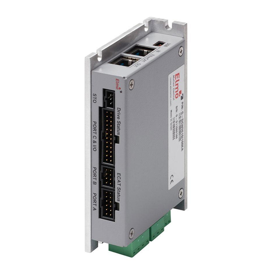
- Page 34 Gold DC Whistle Installation Guide MAN-G-DCWHIIG-EC (Ver. 1.705) 6.4. Drive Status Indicator Figure 15 shows the position of the red/green dual LED, which is used for immediate indication of the Initiation and Working states. For details refer to Chapter 7 Drive Status Indicator, in the MAN-G-Panel Mounted Drives Hardware manual.
- Page 35 Gold DC Whistle Installation Guide MAN-G-DCWHIIG-EC (Ver. 1.705) 6.5. STO (Safe Torque Off) (J11) See Chapter 9 in the in the MAN-G-Panel Mounted Drives Hardware manual for full details. Pin (J11) Signal Function STO1 STO1 input (default 24 V) STO2 STO2 input (default 24 V) STO_RET STO signal return...
- Page 36 Gold DC Whistle Installation Guide MAN-G-DCWHIIG-EC (Ver. 1.705) 6.5.1. Source Mode – PLC Voltage Level Refer to the diagrams below for the PLC Source option connection. Figure 17: STO Molex Type Input Connection – PLC Source Option 6.5.2. TTL Mode – TTL Voltage Level Refer to the diagrams below for TTL option connection.
- Page 37 Gold DC Whistle Installation Guide MAN-G-DCWHIIG-EC (Ver. 1.705) 6.5.3. Sink Mode – PLC Voltage Level Refer to the diagrams below for the PLC Sink option connections which is not fully certified for STO. This option is not recommended for new designs. Figure 19: STO Input Connection –...
- Page 38 Gold DC Whistle Installation Guide MAN-G-DCWHIIG-EC (Ver. 1.705) 6.6. Port A (J1) See Section 10.3 in the in the MAN-G-Panel Mounted Drives Hardware manual for full details. Incremental Encoder Absolute Serial Encoder Pin (J1) Signal Function Signal Function Encoder +5V supply Encoder +5V supply COMRET Common return...
- Page 39 Gold DC Whistle Installation Guide MAN-G-DCWHIIG-EC (Ver. 1.705) 6.6.1. Incremental Encoder Figure 20: Port A Molex Type Incremental Encoder Input – Recommended Connection Diagram 6.6.2. Halls Sensor Figure 21: Molex Type Hall Sensors Connection Diagram Table of Contents ||Port A (J1)|www.elmomc.com...
- Page 40 Gold DC Whistle Installation Guide MAN-G-DCWHIIG-EC (Ver. 1.705) 6.6.3. Absolute Serial Encoder The following figures describe the connections at Port A for the Absolute Serial type encoders. Figure 22: Absolute Serial Encoder – Recommended Connection Diagram for EnDAT, Biss, SSI Figure 23: Absolute Serial Encoder –...
- Page 41 Gold DC Whistle Installation Guide MAN-G-DCWHIIG-EC (Ver. 1.705) 6.6.3.1. Hiperface The following figure describes the connection diagram. Figure 24: Absolute Serial Encoder – Recommended Molex Type Connection Diagram for Stegmann Hiperface Table of Contents ||Port A (J1)|www.elmomc.com...
- Page 42 Gold DC Whistle Installation Guide MAN-G-DCWHIIG-EC (Ver. 1.705) 6.7. Port B (J3) See Section 10.4 in the in the MAN-G-Panel Mounted Drives Hardware manual for full details. Incremental or Resolver Interpolated Analog Encoder G-DCWHIXXX/YYYYEXX G-DCWHIXXX/YYYYRXX Pin (J3) Signal Function Signal Function Encoder +5V supply COMRET...
- Page 43 Gold DC Whistle Installation Guide MAN-G-DCWHIIG-EC (Ver. 1.705) 6.7.1. Incremental Encoder The following figure describes the connections at Port B for the Incremental encoder. Figure 25: Port B Incremental Encoder Input – Recommended Connection Diagram Table of Contents ||Port B (J3)|www.elmomc.com...
- Page 44 Gold DC Whistle Installation Guide MAN-G-DCWHIIG-EC (Ver. 1.705) 6.7.2. Interpolated Analog Encoder The following figure describes the connections at Port B for the Interpolated Analog encoder. Figure 26: Port B - Interpolated Analog Encoder Molex Type Connection Diagram Table of Contents ||Port B (J3)|www.elmomc.com...
- Page 45 Gold DC Whistle Installation Guide MAN-G-DCWHIIG-EC (Ver. 1.705) 6.7.3. Resolver Figure 27: Port B – Resolver Molex Type Connection Diagram Table of Contents ||Port B (J3)|www.elmomc.com...
- Page 46 Gold DC Whistle Installation Guide MAN-G-DCWHIIG-EC (Ver. 1.705) 6.8. Port C, Digital I/Os, and Analog Inputs (J2) The Port C connector includes the following functions: • Port C: Refer to Sections 10.5 in the in the MAN-G-Panel Mounted Drives Hardware manual for full details •...
- Page 47 Gold DC Whistle Installation Guide MAN-G-DCWHIIG-EC (Ver. 1.705) Pin Positions Cable Connector 24-Pin Molex Plug This cable is included in the cable kit described in Section 3.1.1. 24-Pin 2.54 mm Pitch Molex Table 9: Port C Feedback Out and I/O Table of Contents ||Port C, Digital I/Os, and Analog Inputs (J2)|www.elmomc.com...
- Page 48 Gold DC Whistle Installation Guide MAN-G-DCWHIIG-EC (Ver. 1.705) 6.8.1. Port C – Emulated Encoder Output The following figure describes the connections at Port C for the Emulated Encoder Differential. Figure 28: Emulated Encoder Differential Output – Recommended Connection Diagram Note that the user is required to connect a 120 Ω termination at the end of each differential line. Table of Contents ||Port C, Digital I/Os, and Analog Inputs (J2)|www.elmomc.com...
- Page 49 Gold DC Whistle Installation Guide MAN-G-DCWHIIG-EC (Ver. 1.705) 6.8.2. Analog Input The following circuit describes the internal interface of the Analog input. Figure 29: Differential Analog Input Table of Contents ||Port C, Digital I/Os, and Analog Inputs (J2)|www.elmomc.com...
- Page 50 Gold DC Whistle Installation Guide MAN-G-DCWHIIG-EC (Ver. 1.705) 6.8.3. Digital Input and Output TTL Mode The following figure describes the connections at the I/O Port for the Digital Input and Output TTL Mode. Figure 30: Digital Input TTL Mode Connection Diagram Table of Contents ||Port C, Digital I/Os, and Analog Inputs (J2)|www.elmomc.com...
- Page 51 Gold DC Whistle Installation Guide MAN-G-DCWHIIG-EC (Ver. 1.705) Figure 31: Digital Output Connection Diagram – TTL Option Table of Contents ||Port C, Digital I/Os, and Analog Inputs (J2)|www.elmomc.com...
- Page 52 Gold DC Whistle Installation Guide MAN-G-DCWHIIG-EC (Ver. 1.705) 6.8.4. Digital Input and Output PLC Source Mode The following figure describes the connections at the I/O Port for the Digital Input and Output PLC Mode. Figure 32: Digital Input Connection Diagram – Source PLC Option Table of Contents ||Port C, Digital I/Os, and Analog Inputs (J2)|www.elmomc.com...
- Page 53 Gold DC Whistle Installation Guide MAN-G-DCWHIIG-EC (Ver. 1.705) Figure 33: Digital Output Connection Diagram – Source PLC Option Table of Contents ||Port C, Digital I/Os, and Analog Inputs (J2)|www.elmomc.com...
- Page 54 Gold DC Whistle Installation Guide MAN-G-DCWHIIG-EC (Ver. 1.705) 6.8.5. Digital Input and Output Sink Mode The following figure describes the connections at the I/O Port for the Digital Input and Output Sink Mode. Figure 34: Digital Input Sink Mode – PLC voltage level Molex Type Connection Diagram Table of Contents ||Port C, Digital I/Os, and Analog Inputs (J2)|www.elmomc.com...
- Page 55 Gold DC Whistle Installation Guide MAN-G-DCWHIIG-EC (Ver. 1.705) Figure 35: Digital Output as Sink Configuration Molex Type Connection Diagram Table of Contents ||Port C, Digital I/Os, and Analog Inputs (J2)|www.elmomc.com...
- Page 56 Gold DC Whistle Installation Guide MAN-G-DCWHIIG-EC (Ver. 1.705) 6.9. USB 2.0 (J9) See Section 12.1 in the in the MAN-G-Panel Mounted Drives Hardware manual for full details. Pin (J9) Signal Function USB VBUS USB VBUS 5 V USBD- USB _N line USBD+ USB _P line USB COMRET...
- Page 57 Gold DC Whistle Installation Guide MAN-G-DCWHIIG-EC (Ver. 1.705) 6.10. EtherCAT Communication Version Fieldbus communications are industrial network protocols for real-time distributed control that allows connection of servo drives. The Gold DC Whistle supports the following EtherCAT fieldbus type industrial network protocol: Fieldbus Type Product Number EtherCAT...
- Page 58 Gold DC Whistle Installation Guide MAN-G-DCWHIIG-EC (Ver. 1.705) 6.10.2. EtherCAT OUT Pin Assignments (J8) See Section 12.2 in the MAN-G-Panel Mounted Drives Hardware manual for the electrical diagram. Pin (J8) Signal Function EtherCAT_OUT_TX+ EtherCAT out transmit + EtherCAT_OUT_TX- EtherCAT out transmit - EtherCAT_OUT_RX+ EtherCAT out receive + 4, 5...
- Page 59 Gold DC Whistle Installation Guide MAN-G-DCWHIIG-EC (Ver. 1.705) 6.10.4. EtherCAT Status Indicator Figure 38: EtherCAT Status LED The EtherCAT status indicator is a single red/green dual bi-colored LED that combines the green RUN indicator and the red ERROR indicator of the EtherCAT state machine. For further details, see the EtherCAT Application Manual.
- Page 60 Gold DC Whistle Installation Guide MAN-G-DCWHIIG-EC (Ver. 1.705) 6.11. CAN Communication Version Fieldbus communications are industrial network protocols for real-time distributed control that allows connection of servo drives. The Gold DC Whistle supports the following CAN fieldbus type industrial network protocol: Fieldbus Type Product Number G-DCWHI XX/YYYSXX...
- Page 61 Gold DC Whistle Installation Guide MAN-G-DCWHIIG-EC (Ver. 1.705) 6.11.1. CAN Wiring Caution When installing the CAN communications, ensure that each servo drive is allocated a unique ID. Otherwise, the CAN network may hang. Figure 40: Gold DC Whistle Connection Diagram – CAN Table of Contents ||CAN Communication Version|www.elmomc.com...
- Page 62 After the Gold DC Whistle has been connected and mounted, the system must be set up and initialized. This is accomplished using the EASII, Elmo’s Windows-based software application. Install the application and then perform setup and initialization according to the directions in the EASII User Manual.
- Page 63 Gold DC Whistle Installation Guide MAN-G-DCWHIIG-EC (Ver. 1.705) Chapter 7: Dim ensions This chapter provides detailed technical information regarding the Gold DC Whistle. Table of Contents ||www.elmomc.com...
- Page 64 Table of Contents ||www.elmomc.com...
Need help?
Do you have a question about the Gold DC Whistle Series and is the answer not in the manual?
Questions and answers