
Related Manuals for NKE HR Masthead unit


Summary of Contents for NKE HR Masthead unit
- Page 1 HR Masthead unit Product reference : 90-60-369 USER GUIDE INSTALLATION GUIDE Zi de Kerandré – Rue Gutemberg – 56700 – HENNEBONT – FRANCE www.nke-marine-electronics.com...
-
Page 2: Table Of Contents
TABLE OF CONTENTS USING ....................................3 ................................3 RESENTATION ............................4 IST OF CHANNELS DISPLAYED ................................4 LARMS SETTING ............................4 ILTERING OF THE CHANNELS ..............................5 HOICE OF THE UNIT ............................5 ECHNICAL SPECIFICATIONS ......................5 IAGNOSTIC OF LEVEL TROUBLESHOOTING CALIBRATION .................................. -
Page 3: Using
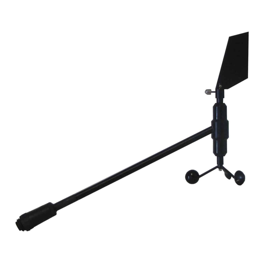
USING 1.1 PRESENTATION The HR masthead unit is a measuring instrument for wind speed and direction. It is connected to the TOPLINE bus of your installation. Equipped with high quality ball bearings and mechanical elements of precision, the HR masthead unit guaranteed qualities of a reliable, precise and sensitive sensor. -
Page 4: List Of Channels Displayed
1.2 LIST OF CHANNELS DISPLAYED The masthead unit, connected to the TOPLINE bus of your installation, creates the channels below. They are then accessible using the displays of the TOPLINE range. Channel Display Unit 0.0Kt m/s or knot WIND SPD / A Apparent wind speed 0°... -
Page 5: Choice Of The Unit
1.5 CHOICE OF THE UNIT You have the option to choose the following display units : Wind speed : in knots or in m/s. Air temperature : in degree Fahrenheit or in degree Celsius Please refer to the user guide of your display to carry out this change of units. 1.6 TECHNICAL SPECIFICATIONS Power supply : 10 to 16VDC Consumption : 25mA... -
Page 6: Calibration
CALIBRATION The masthead unit is adjusted at the factory. However, a calibration is required to adapt the sensor to the specificities of your boat and to obtain an optimum measurement accuracy. Follow the calibration procedure below, by visualising the settings on a display: please refer to the user guide of the display. -
Page 7: Calibration Of The Anemometer
2.2 CALIBRATION OF THE ANEMOMETER 2.2.1 Principle of the calibration You will adjust the calibration coefficient of the channel apparent wind speed, so that the speed displayed is equal to the true ambient wind speed. You can carry out this calibration at port. 2.2.2 Setting procedure of the calibration coefficient 1. -
Page 8: Installation
INSTALLATION The masthead unit is attached to the mast using a plate support. Two versions are available: − 90-60-509 plate equipped with 25 meters of cable. − 90-60-562 plate equipped with 35 meters of cable. Measure the length of cable necessary to connect the sensor, attached at the head of mast, to the TOPLINE bus terminal box inside your boat. -
Page 9: Installation Of The Mounting Plate And Of The Vane Support
3.3 INSTALLATION OF THE MOUNTING PLATE AND OF THE VANE SUPPORT The attachment system of the wind vane comprises a vane support. You will start by attaching the support at the head of the mast, then you will mount the wind vane onto the support. The support is assembled using two screws. -
Page 10: Maintenance
VITES 1.20 SURF Supply 12Vdc DATA black 12VDC White connecting box 90-60-121 Figure 4 : connection to the TOPLINE bus If you cut the bus cable, you will need to galvanise the wires after stripping them. MAINTENANCE The axes of the wind vane and of the anemometer are mounted on ball bearings and rotate permanently.
Need help?
Do you have a question about the HR Masthead unit and is the answer not in the manual?
Questions and answers