
Related Manuals for NKE Pad Display


Summary of Contents for NKE Pad Display
- Page 1 Pad Display Part number: 90-60-545 Pad Display White 90-60-546 Pad Display Carbon User Guide & Installation manual V1.3 Zi de Kerandré – Rue Gutenberg – 56700 – HENNEBONT www.nke-marine-electronics.fr...
-
Page 2: Table Of Contents
......................3 Key pad description ..................3 Settings of the Pad Display ................. 5 Set up an address for the Pad Display ............5 Key sound ..................... 5 Use in a topline Bus ..................... 6 Select of a display ..................6 Shortcut Pages A, B, C, D ................ -
Page 3: Introduction
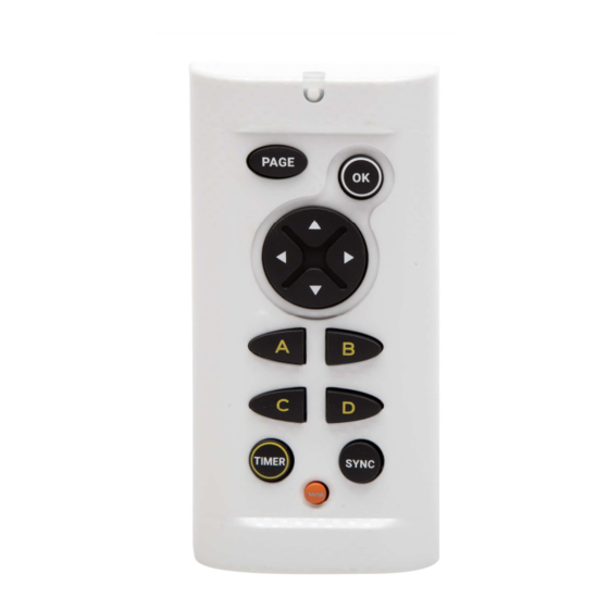
1. INTRODUCTION The Pad Display is a control for the Topline Bus. It is used to control Multidisplay, Multigraphic displays, to manage the timer and the display standby control. 2. OPERATION The Pad Display is given a node address, like a display. When the Pad Display is powered for the first time, the default address is 0 (factory setting). - Page 4 • RED LED Led indicating the current mode for the Pad Display (display selection mode, set-up mode) Flashes at each press. • PAGE Use this key to navigate in various displays of the Topline range. Press and hold to access the display selection mode.
-
Page 5: Settings Of The Pad Display
3. SETTINGS OF THE PAD DISPLAY 3.1 Set up an address for the Pad Display When the Pad Display is powered for the first time, the default address is 0, the LED flashes once per second, waiting for the operational node address. Press allocate an address. -
Page 6: Use In A Topline Bus
4. USE IN A TOPLINE BUS 4.1 Select of a display To select a display with the Pad Display, press until the second beep (5 seconds). You’ve accessed the selection mode. Then press on the left or right arrow to toggle between displays. You may press several times until you find the desired display. -
Page 7: Shortcut Pages A, B, C, D
Keys A, B, C, D are used to call up programmed pages or the standby command in the Multigraphic and Multidisplay displays. Example: I have a Pad Display, a Multidisplay and a Multigraphic in my Topline installation. My two displays have the A key programmed. When I press the A key on my Pad, I bring up the programmed page of each display. -
Page 8: Key Ok (T1 Et T2)
TIMER via the menu. (§4.3.2) 4.3.2 Key OK (T1 et T2) When you select a Multidisplay or a Multigraphic with the PAD Display and you display a page where the TIMER channel appears, pressing causes the appearance of popup windows: - First popup: "Arm TIMER T1". -
Page 9: Installation
Turn the power supply OFF before doing any work on the TOPLINE Bus. 5.1 Pad Display packing list Ecrou plastique Fixamo - A Pad Display with a six meters cable. - A protection cover. - A Fixamo M14. - A plastic M14 nut. 5.2 Wiring the Pad Display Connect the bus cable to a Topline junction box as follow: White wire on "+12 V white"... -
Page 10: Mounting The Pad Display
5.3 Mounting the Pad Display There are several ways to mount the Pad Display: An 18 mm diameter hole is required to allow the cable running as well as the mounting kit. If the supporting surface is between 1 and 3mm: Screw the plastic nut by hand. -
Page 11: Specifications Of The Pad Display
DRILLING TEMPLATE 6. SPECIFICATIONS OF THE PAD DISPLAY Parameter Value With protection cover (mm): 122 x 62 x 27 (Length x Width x Depth) Dimensions Without protection cover (mm): 115 x 58 x 23 (Length x Width x Depth) - Hand-screw nut M14 (part Nr: 30-95-032) -
Page 12: Firmware Evolution For The Pad Display
7. FIRMWARE EVOLUTION FOR THE PAD DISPLAY Date Information V1.0 21/06/2018 Original version V1.1 08/11/2018 Bug correction for long auto shortcut Possibility to acknowledge the TOPLINE Bus audible alarms Compatibility with HR and Regatta processors V1.2 11/03/2020 Removal of standby of the pad V1.3...
Need help?
Do you have a question about the Pad Display and is the answer not in the manual?
Questions and answers