
Subscribe to Our Youtube Channel
Related Manuals for NKE CARBOWIND HR


Summary of Contents for NKE CARBOWIND HR
- Page 1 Masthead unit CARBOWIND HR Product reference : 90-60-370 USER GUIDE INSTALLATION GUIDE Zi de Kerandré – Rue Gutemberg – 56700 – HENNEBONT – FRANCE www.nke-marine-electronics.com...
-
Page 2: Table Of Contents
INSTALLATION ................................. 8 ..............................8 IST OF ACCESSORIES ............................8 INSTALLATION CAUTIONS ............................... 8 IXING THE CABON TUBE CARBOWIND HR ......................11 ETTING THE HEIGHT OF THE ..........................11 INDMILL MONTING PROCEDURE ............................. 12 ONNECTING TO TOPLINE BUS MAINTENANCE ................................13 38_Carbowind_HR_um_UK_28... -
Page 3: Using
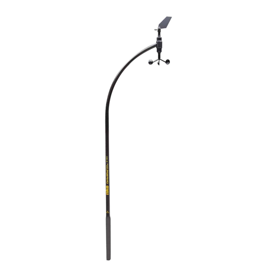
1 USING 1.1 PRESENTATION The CARBOWIND HR is a measuring instrument for wind speed and direction. It is connected to the TOPLINE bus of your installation. Equipped with high quality ball bearings and mechanical elements of precision, the CARBOWIND HR unit guaranteed qualities of a reliable, precise and sensitive sensor. -
Page 4: List Of Channels Displayed
For channel settings, please refer to your TOPLINE display guide 1.2 LIST OF CHANNELS DISPLAYED The CARBOWIND HR, connected to the TOPLINE bus of your installation, creates the channels below. They are then accessible using the displays of the TOPLINE range. -
Page 5: Filtering Of The Channels
1.4 FILTERING OF THE CHANNELS The level of filtering of a channel determines the frequency of update of the data displayed. For example, in rough sea when the boat moves significantly, it is useful to increase the filtering of the speed channel to stabilise the value displayed. Conversely, in calm sea, low filtering will be preferable to obtain a fast response of the display. -
Page 6: Calibration
2 CALIBRATION The CARBOWIND HR is adjusted at the factory. However, a calibration is required to adapt the sensor to the specificities of your boat and to obtain an optimum measurement accuracy. Follow the calibration procedure below, by visualising the settings on a display : please refer to the user guide of the display. -
Page 7: Calibration Of The Anemometer
2.2 CALIBRATION OF THE ANEMOMETER 2.2.1 Principle of the calibration You will adjust the calibration coefficient of the channel apparent wind speed, so that the speed displayed is equal to the true ambient wind speed. You can carry out this calibration at port. 2.2.2 Setting procedure of the calibration coefficient 1. -
Page 8: Installation
Note that, the internal diameter of the support tube is perfectly adjusted, so that there is no play with the CARBOWIND HR pole and that the whip of it does not cause the initiation of rupture. Warranty conditions Carbowind HR reference 90-60-370-012 –... - Page 9 Please observe the following assembly. 38_Carbowind_HR_um_UK_28...
- Page 10 2. In the case of mounting on the side of the mat. It must be stratified over the entire height, leaving 20 to 30 mm free for the installation of a heat- shrinkable sheath. It is advisable to leave the bottom free to allow the extraction of Carbowind. For anti-extraction, make a textile bristle fixed on the mast or put a small diameter screw in the lower part of the sleeve.
-
Page 11: Setting The Height Of The Carbowind Hr
3.4 SETTING THE HEIGHT OF THE CARBOWIND HR The CARBOWIND HR is delivered with a carbon tube with a length of 1.20 meters. The tube can be shortened in the case of mounting on a mat having the old round sleeve. In this case the Carbowind cable comes out from the bottom of the tube after having cut it at the yellow line level. -
Page 12: Connecting To Topline Bus
3.6 CONNECTING TO TOPLINE BUS If the cable runs inside the mast, make the cable pass through an opening equipped with a grommet. If the cable runs across the deck, make the cable pass through a tight stern tube gland. 1. -
Page 13: Maintenance
4 MAINTENANCE The axes of the wind vane and the anemometer are mounted on ball bearings, and rotate continuously. If possible, we advise you to disassemble the wind vane from its support, during wintering periods, to increase the life of the bearings. If you put down the wind vane, for dismasting or wintering for example, protect the cable plug to prevent water ingress.
Need help?
Do you have a question about the CARBOWIND HR and is the answer not in the manual?
Questions and answers