
Related Manuals for NKE MULTIDISPLAY


Summary of Contents for NKE MULTIDISPLAY
- Page 1 MULTIDISPLAY Item number: 90-60-543 USER MANUAL & INSTALLATION SHEET V1.1 6 Rue Gutemberg - Zi de Kerandré 56700 – HENNEBONT – FRANCE www.nke-marine-electronics.com +33 297 365 685...
-
Page 2: Table Of Contents
A,B,C,D keys configuration of the multifunction Pad ..............14 2.5.8 Language selection ........................14 2.5.9 Unit selection ..........................14 2.5.10 Maintenance..........................15 2.5.10.1 Multidisplay node address in the Topline system ................15 2.5.10.2 Auxiliary inputs ............................ 16 2.5.10.3 Topline Instrument system ........................16 2.5.10.4 Orientation ............................17 2.5.10.5 Keypad Beep ............................ - Page 3 ..............48 NSTALLATION AND RECOMMENDATION FOR THE MAST MOUNT BRACKET ....................49 CONNECTION TO THE TOPLINE BUS AND NMEA 3.7 ..................................50 ......................50 ODE ADRESS FOR THE MULTIDISPLAY NMEA ..................50 CONNECTING TO A SOURCE AND CONFIGURATION 3.10 .................. 51 INSTALLATION AND CONFIGURATION OF THE GYROPILOT MULTIDISPLAY SPECIFICATIONS ....................
-
Page 4: Presentation
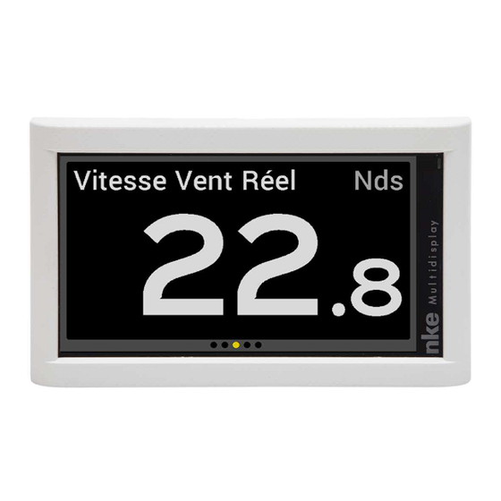
1 PRESENTATION Thank you for purchasing the nke Multidisplay. The Multidisplay features a 7 inch colour screen. A transflective polarizer enhances daylight reading and integrated LED backlighting ensures clear readability at night. The backlight intensity can be automatically adjusted or user adjusted. -
Page 5: Menu Page
• -1, +1, -10, +10 (Pad Pilot) Use to control the autopilot’s course in 1° or 10° increments to Port or Starboard. Press and hold the 10° to tack. • AUTO Single press to engage the autopilot. Press and hold this key to go directly to the Pilot Mode menu. •... -
Page 6: Page Building Wizard
When the Multidisplay is used for the first time it displays a screen with a menu providing access to: • the sensor settings • the alarm settings • the pilot settings • the Performance page setup • the parameter settings Press the cursor pad’s arrows «... - Page 7 8 information according to the phases of race, those information can be read on these alternative pages. This information can be read on all Multidisplay of the Topline network. The 8 channels available are named DYN1 to DYN8. Page 7/55...
-
Page 8: Edit A Page
2.2.2 Edit a page This setting selects the data that will be displayed on the selected page FOLLOWING to accept the current data in that selected part of the screen (only for multiple line pages) and go to the next page partition. MODIFY to change the information and the colour in which it will be displayed by selecting from a list. - Page 9 BAT1 Energy BAT2 Voltage Timer Optimum Wind Angle Performance Drift Angle Direction of measured current Speed of measured current Speed over ground Heading over the ground Magnetic COG Distance to Waypoint Bearing to Waypoint Cross-Track Error Position Time Date Declination Air Pressure Weather Sea temperature...
-
Page 10: Visible
Once the page has been built a window opens allowing you to save and rename the page. Press to save the page. Select Name with the pad and press button to access the virtual keyboard. Use the pad keys to select letters and press to confirm your choice. -
Page 11: Use Of The Multigraphic As Multifunction Display
2.4 USE OF THE MULTIDISPLAY AS MULTIFUNCTION DISPLAY Multidisplay is a multifunction display from the TOPLINE range of products. It connects to the TOPLINE bus on your system and displays all data available on the bus. The keyboard, curser pad and scroll down menus make all aspects of the system easy to use. -
Page 12: Display Settings
2.5.1 Display Settings The Display Settings menu gives access to: • The Display Mode • The Daylight Mode settings • The Night Mode settings • The Stand-by timing 2.5.2 Backlighting The backlighting can toggle automatically between Night and Day settings, driven by a light sensor, or can be manually set. -
Page 13: Skin Settings
• Press again and modify the value « light level » with . Then press to save the parameter. 2.5.4 Skin Settings • In « parameters » choose « Display Setting » and press • Choose « Day adjustment » or « Night adjustment » and press •... -
Page 14: Data Logging : " Stripcharts " Settings
Language setting process: In « parameters » choose the language and press to save your choice. 2.5.9 Unit selection The Multidisplay can be set to use various units for boat speed, depth, air temperature, sea temperature and wind speed. Page 14/55 68_Afficheur_Multidisplay_um_UK_11... -
Page 15: Maintenance
« Master » and manages the whole system. If there is already a Master », the Multidisplay will get an address different from 1 and it will behave as « Slave ». This process is carried out automatically: if there is no «... -
Page 16: Auxiliary Inputs
Once this procedure is complete, the Pad won’t have any control on the Multidisplay, you’ll have to execute the address taking process to be able to control the display. In case of “master bus lost” it is possible to reconnect the red wire to reset the address to zero and start the address taking process. -
Page 17: Orientation
2.5.10.4 Orientation It is possible to change the layout of your Multidisplay. To do so, go in >> parameters >> maintenance >> orientation: select « landscape » or « Portrait » and save with WARNINGS: By default, the Multidisplay is in landscape with the logo nke on the right. In portrait, the logo is at the bottom of the screen. -
Page 18: Autotest
2.5.10.9 Autotest Autotest is useful to check the Multidisplay. This procedure verifies the following functions step by step: • keys • colour display • light sensor (vlight), internal temperature sensor, power supply. • backlighting • memory • Topline bus • NMEA input and output (connect the yellow and red wires together for that operation). -
Page 19: Sensor Settings
2.6 SENSOR SETTINGS Go to the main menu by pressing and select to display the « sensors » page. All sensors connected to the Topline bus can be calibrated from this menu. Settings are different for each sensor. Refer to the sensor’s manual for more information. Main settings: •... -
Page 20: Speed Through Water Calibration Wizard
Calibration of the Apparent Wind Angle: • Select « Apparent Wind Angle » and press • Choose « Calibration Wizard » and press • Select « Start » and press • Go on Starboard Tack and press . Wait and press •... -
Page 21: Compass Auto-Adjustment
This page displays the current calibration value (old correction), the new calibration value (new correction), the factors calculated from the runs (ratio FW/BW) and the correction factor for boat speed. 2.6.4 Compass Auto-adjustment Some magnetic deviation errors are unique to each boat, due to the magnetic environment. -
Page 22: Compass Deviation Table
2.6.8 Compass adjustement wizard This method can only be used with the fluxgate compass It consists of sailing the boat on the nke compass heading (+/-5°), comparing this heading with the magnetic heading over the ground and noting the value every 30° to determine the values for the correction table. -
Page 23: Drift Angle
. You will have to follow nke compass information as precisely as possible every 30°. • Choose « start » and confirm with OK. Follow nke compass’ instructions as precisely as possible every 30°. • Once nke compass is ready choose “validate” and press . -
Page 24: Sensor Access Code
navigation conditions. Therefore, it has to be an average value, valid for all weather conditions or alternatively, you can alter that value upon the wind strength. The drift angle for each boat speed and heel angle is shown with the polar tables supplied by your architect. -
Page 25: Alarms Settings
• Choose a code and enter it with the keypad appearing on the screen. Select Enter and press Procedure to unlock the sensor menu: • Enter into « Sensors » • Enter the code configurated previously. • Select “Ent” and press •... -
Page 26: Activation Of An Alarm
If you want the rest of your instruments to ring when an alarm triggers on the Multidisplay, you need to activate the Topline alarm, first line in the alarm menu. RACE TIMER The race timer works as a countdown before the start of a race. Two different race procedures can be set up as «... -
Page 27: Setting The Race Timer
Press for a while to start the timer. • 1st short press to start T1 • 2nd short press to start T2 2.8.2 Setting the race timer The default settings are 5 minutes for « T1 » and 4 minutes for « T2 ». Here is the procedure to set the timers to your own values: •... -
Page 28: True Wind Tables
2.9.2 True wind tables The data measured by the wind sensor placed on top of the mast, even when on a long carbon arm, is affected by the sails. The wind flow is disturbed around the sails and rig. This is called the “upwash”. This “upwash”... -
Page 29: True Wind Speed Table
• Select « Performance » and press • Choose « Wind Table » and press • Choose « True Wind Angle Table » and press • Select the value you need to modify and save with Select the value to be corrected. Modify the value The column on the left indicates the true wind speed in knots, the “V1”... -
Page 30: Statistics For The Last Hour
2.9.7 Statistics for the last hour True Wind Direction, average of the true wind direction during the past hour. Wind shift, calculation of the true wind direction standard deviation for the past hour. Average wind speed, average of the true wind speed data for the past hour. Gusts, calculation of the of true wind speed standard deviation for the past hour. -
Page 31: Calibrations Order
Apparent wind calibration True wind correction tables For sensor calibration, see the “Sensors setting” section. 2.11 MULTIDISPLAY OPERATION WITH THE GYROPILOT 2 PROCESSOR Gyropilot is an automatic pilot designed to steer the boat. It is intended to assist the helmsman and should never be used without state of the art navigation equipment handled by a qualified navigator. - Page 32 From that point the processor uses the data coming from the sensors to control the rudder using the following criteria: - the error to the course to steer, from data coming in from the compass (compass mode) or the wind unit (wind mode). - the boat motion delivered by the gyrometer.
-
Page 33: Keys To Control The Gyropilot
2.11.1 Keys to control the Gyropilot In order to control the pilot you need to use a Pad Pilot. Press once to engage the pilot on the current course relevant to the pilot mode selected. In compass mode it will be the compass heading at the time you press the button and in wind mode it will be the wind angle at the time you press the button. -
Page 34: Pilot Page Selection
2.11.2 Pilot page selection 2 different pilot pages are available: analogue format or digital format. 2.11.2.1 Standard page Sensor identification and value related to the pilot mode. Course to steer Access Gain value adjustable pilot mode with Rudder angle with the up and down indicator arrows on the pad Page 34/55... -
Page 35: Custom Page
2.11.2.2 Custom page Pilot’s course to steer User’s selected data, set up according to the user’s preference Pilot Mode. Accessible with Sensor and value for related selected pilot mode. Press to access the pilot mode and settings. Press to cancel the last action. - Page 36 (just watch power consumption). True Wind software add-on A code is required to activate the true wind mode function. Please contact your nke dealer to get this code. The code number is linked to each Gyropilot 2 processor, your dealer will need your processor’s serial number to issue the code for the...
-
Page 37: Pilot Settings
Compass mode This mode requires a speed sensor and a compass sensor. With the compass mode the pilot uses the compass heading data from the Topline bus to steer the boat on a set heading. Rudder mode The rudder mode allows the rudder to be set at a fixed angle. The value can be between –... - Page 38 feature will depend on the type of boat and sea conditions. The boat rotation speed measured by the gyrometer embedded in the Gyropilot processor is used to provide this feature. The factory default setting is AUTO. This adjusts automatically with the gain. The setting value ranges from 1 to 9.
- Page 39 Tack speed The speed at which tacks are performed by the Gyropilot can be set from 1° per second to 32° per second. The default setting is 9° per second. Man Over Board The Man-Over-Board function can be activated from any MOB button on a Topline display or a wireless remote control (Gyropilot, Multifonction or Crew) if the MOB function has been set.
-
Page 40: Gyropilot Operation
Return to manual steering by pressing stop once when you are ready at the helm. The following graphic shows the pilot page as it will be displayed on the Multidisplay when the Gyropilot is engaged in compass mode. Page 40/55... - Page 41 Mode Course to steer Gain Rudder angle Note: when the pilot is disengaged « » is displayed instead of the course to steer. Warning: The Auto button engages the pilot and the Stop button disengages the pilot. Make sure the pilot is disengaged before turning the power supply off. Operation with Apparent wind mode The apparent wind mode requires a compass sensor, a boat speed sensor and a wind sensor.
- Page 42 Using the GPS mode In GPS mode the Gyropilot steers the boat to a route provided by the GPS or the navigation software connected to the NMEA input of your Topline system. To achieve this, the GPS or the navigation software must feed the system with the following NMEA sentences: - $xxXTE : cross-track error and - $xxBWC : bearing and distance to waypoint (DTW and BTW) or...
-
Page 43: Pilot Setup Saving And Recall
The alarm will sound when the wind angle variation is greater than the set value for more than 30 seconds in compass mode and when the heading variation is greater than the set value for more than 30 seconds in wind mode. The Multidisplay will display a message and sound beeps. -
Page 44: Pilot Page On Remote Display
Alarm setup procedure for the pilot: On the pilot page: • Press , a window will open. • Select « Pilot alarms » and press • Select « Wind/head ON/OFF » and press • With your keypad it is possible to modify Wind/head settings but also the battery level. -
Page 45: Installation
INSTALLATION This section describes the installation and configuration of the Multidisplay as well as setting the parameters for an installation with a Gyropilot 2 processor. Refer to the Gyropilot 2 manual for the full pilot installation (drive unit, processor, rudder feed-back…). -
Page 46: Before Installing Check
Warning: The default factory setting of your Multidisplay is landscape orientation with the nke logo on the right, If you want to change the orientation see: parameters >> Maintenance. It is recommended to set up the orientation before installing it. - Page 47 Guide size Page 47/55 68_Afficheur_Multidisplay_um_UK_11...
-
Page 48: Installation And Recommendation For The Mast Mount Bracket
MOUNT BRACKET Mechanical resistance for the double vertical mount bracket: In accordance with the dimensions and the aging test report, NKE recommends: A maximum 15kg load in the transverse axis of the boat to preserve the quality of the mount bracket. -
Page 49: Connection To The Topline Bus And Nmea
Make sure the display can’t move by hand once tightened. 3.6 CONNECTION TO THE TOPLINE BUS AND NMEA 1. Run the bus cable from the Multidisplay to the TOPLINE junction of your system. 2. Connect the cable in the junction box. -
Page 50: Node Adress For The Multidisplay
NMEA – 3.7 NODE ADRESS FOR THE MULTIDISPLAY At the first power on, you must give a node address to the Multidisplay to enable it to work on the system’s bus. The default address is 0. During the address taking, connect the red wire on the INIT terminal and start the installation. -
Page 51: Installation And Configuration Of The Gyropilot
3.9 INSTALLATION AND CONFIGURATION OF THE GYROPILOT Once the Gyropilot is installed, you need to configure the system. This consists of teaching the pilot the rudder’s positions: place the rudder in the mid-ship position, then at the starboard lock and then the port lock. These three rudder positions are essential for the processor to run the drive unit. -
Page 52: Multidisplay Specifications
4 MULTIDISPLAY SPECIFICATIONS Feature Value Dimensions With sun cover: 196 x 122 x 28mm (length x height x depth) Without sun cover: 192 x 118 x 23mm ((length x height x depth) Weight 850g with 6m de cable (32g/m) and sun cover Power supply DC (continue) 8V –... -
Page 53: Events Messages
5 EVENTS MESSAGES Message at system start up, indicating the Multidisplay address. Multidisplay being set as “Master”, when the system creates the list (search all sensors and displays in the bus), it displays addresses for slave displays. The “master” display is unplugged or out of order. - Page 54 This page is shown when the Man Over Board function has been triggered. The dead reckoned distance and bearing to the man over board are displayed together with the boat’s course over ground. The timer is triggered to give the time from event.
-
Page 55: Multidisplay Software Evolution
6 MULTIDISPLAY SOFTWARE EVOLUTION YOU CAN HELP PROTECT THE ENVIRONMENT! Please remember to respect the local regulations: Hand in the non-working electrical equipment to an appropriate waste disposal center. Page 55/55 68_Afficheur_Multidisplay_um_UK_11...
Need help?
Do you have a question about the MULTIDISPLAY and is the answer not in the manual?
Questions and answers