Comtech EF Data LBC-4000 Installation And Operation Manual
L-band up/down converter system
Hide thumbs
Also See for LBC-4000:
- Installation and operation manual (108 pages) ,
- Installation and operation manual (166 pages) ,
- Installation and operation manual (62 pages)
Table of Contents
Advertisement
Quick Links
LBC-4000
L-Band Up/Down Converter System
Installation and Operation Manual
Firmware Version 1.2.5 and Higher
Includes Model LBC-4000-ST
Part Number MN-LBC-4000
Revision
6
IMPORTANT NOTE: The information contained in this document supersedes all previously published
information regarding this product. Product specifications are subject to change without prior notice.
Advertisement
Table of Contents

Related Manuals for Comtech EF Data LBC-4000


Summary of Contents for Comtech EF Data LBC-4000
- Page 1 LBC-4000 L-Band Up/Down Converter System Installation and Operation Manual Firmware Version 1.2.5 and Higher Includes Model LBC-4000-ST Part Number MN-LBC-4000 Revision IMPORTANT NOTE: The information contained in this document supersedes all previously published information regarding this product. Product specifications are subject to change without prior notice.
- Page 2 LBC-4000 Revision 6 Copyright © 2020 Comtech EF Data. All rights reserved. Printed in the USA. Comtech EF Data, 2114 West 7th Street, Tempe, Arizona 85281 USA, 480.333.2200, FAX: 480.333.2161 Revision History Date Description 0 - 4 Varies Various updates.
-
Page 3: Table Of Contents
LBC-4000 L-Band Up/Down Converter System Revision 6 Table of Contents PREFACE ..............................I About this Manual ............................i Disclaimer ..............................i Conventions and References........................i Patents and Trademarks ..........................i Warnings, Cautions, Notes, and References ..................... ii Examples of Multi-Hazard Notices ......................ii Recommended Standard Designations ..................... - Page 4 Power Interface Module – Standard AC Unit .............. 4–10 4.2.3.2 AC Operation Prime Power Connection ..............4–10 4.2.3.3 LBC-4000 Optional -48 VDC Filter Input Module ............4–11 4.2.3.5 Chassis Ground Interface ................... 4–12 4.2.3.6 LBC-4000 ON/OFF Power Switch ................4–12 CHAPTER 5.
- Page 5 LBC-4000 L-Band Up/Down Converter System Revision 6 5.2.4.2 Windows Explorer Folder Creation ................5–7 5.2.4.3 Run and Browse Windows Folder Creation ..............5–7 5.2.4.4 Windows Command-line or Command Prompt Folder Creation ........5–8 Download and Extract Firmware Update Files ................. 5–9 5.3.1.1...
- Page 6 LBC-4000 L-Band Up/Down Converter System Revision 6 (UTILITY:) SCRSAVER Time ................6–22 6.3.6.7.2 CHAPTER 7. ETHERNET INTERFACE OPERATION ............... 7–1 Overview ............................7–1 7.1.1 Prerequisites ..........................7–1 SNMP Interface ..........................7–2 7.2.1 Management Information Base (MIB) Files ................7–2 7.2.1.1...
- Page 7 LBC-4000 Front Panel Operations .................... B–3 B.2.1 (CONFIG:) REDUND (Redundancy) Submenu ................ B–3 B.2.2 Gain Offset for Redundant Operations ..................B–4 Redundancy Operations Using the LBC-4000 HTTP Interface ..........B–5 Redundancy Operations Using Serial Remote Control............B–6 Table of Contents TOC-5 MN-LBC-4000...
- Page 8 Figure 4-7. LBC-4000-ST Rear Panel ....................... 4–8 Figure 4-8. AC Power ..........................4–10 Figure 4-9. LBC-4000 Optional -48 VDC Filter Input Module with User-Supplied Power Harness ..4–11 Figure 4-10. Chassis Ground Interface ....................4–12 Figure 4-11. LBC-4000 ON/OFF Power Switch ..................4–12 Figure 6-1.
- Page 9 LBC-4000 L-Band Up/Down Converter System Revision 6 Acronym List First Use Acronym Description Page Numbe Application Identification 6-20 Block Down Converter 7-23 Block Up Converter 7-23 CEFD Comtech EF Data Direct Current Electrostatic Discharge File Transfer Protocol 5-13 Interface Data Unit Light Emitting Diode M&C...
- Page 10 LBC-4000 L-Band Up/Down Converter System Revision 6 Units of Measurement Unit / Symbol Definition Ω Ampere bits per second ˚C Celsius (degrees) Hertz kiloHertz decibel Decibels relative to the carrier Decibel-milliwatts ˚F Fahrenheit (degrees) Kbps Kilobit per second kilogram ksps Kilosymbols per second lbs.
-
Page 11: Preface
LBC-4000/-ST. Disclaimer Comtech EF Data has reviewed this manual thoroughly in order to provide an easy-to-use guide to this equipment. All statements, technical information, and recommendations in this manual and in any guides or related documents are believed reliable, but the accuracy and completeness thereof are not guaranteed or warranted, and they are not intended to be, nor should they be understood to be, representations or warranties concerning the products described. -
Page 12: Warnings, Cautions, Notes, And References
A NOTE gives you important information about a task or the equipment. A REFERENCE directs you to important operational information or details furnished elsewhere, either in the manual or in adjunct Comtech EF Data publications. Examples of Multi-Hazard Notices... -
Page 13: Safety And Compliance
LBC-4000 L-Band Up/Down Converter System Revision 6 Safety and Compliance Electrical Safety and Compliance The unit complies with the EN 60950 Safety of Information Technology Equipment (Including Electrical Business Machines) safety standard. Electrical Installation CONNECT THE UNIT TO A POWER SYSTEM THAT HAS SEPARATE GROUND, LINE AND NEUTRAL CONDUCTORS. -
Page 14: European Union Electromagnetic Compatibility (Emc) Directive (2004/108/Ec)
LBC-4000 L-Band Up/Down Converter System Revision 6 European Union Electromagnetic Compatibility (EMC) Directive (2004/108/EC) • EN 55022 Class A (Emissions) – Limits and Methods of Measurement of Radio Interference Characteristics of Information Technology Equipment. • EN 55024 (Immunity) – Information Technology Equipment: Immunity Characteristics, Limits, and Methods of Measurement. -
Page 15: European Union Rohs Directive (2002/95/Ec)
Comtech EF Data is responsible for the freight charges only for return of the equipment from the factory to the owner. Comtech EF Data will return the equipment by the same method (i.e., Air, Express, Surface) as the equipment was sent to Comtech EF Data. -
Page 16: Limitations Of Warranty
Comtech EF Data Corporation, would affect the reliability or detracts from the performance of any part of the product, or is damaged as the result of use in a way or with equipment that had not been previously approved by Comtech EF Data Corporation. -
Page 17: Chapter 1. Introduction
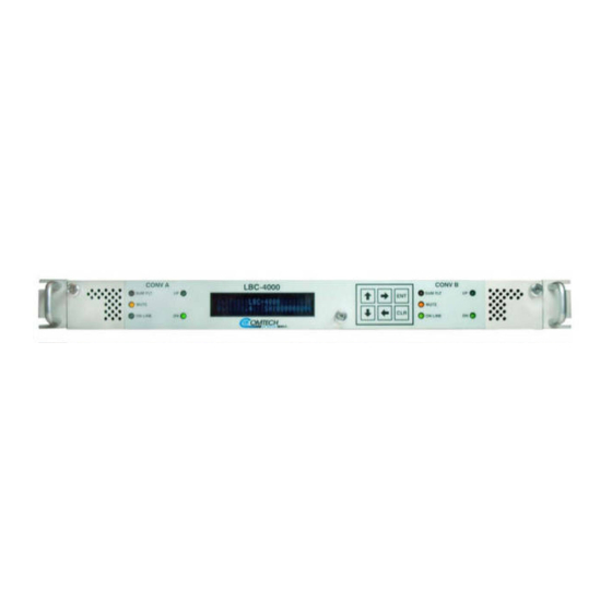
Revision 6 Chapter 1. INTRODUCTION Overview Comtech EF Data (CEFD)’s LBC-4000 (Figure 1-1) and the LBC-4000-ST (Figure 1-2) L-Band Up/Down Converter System are designed to interface legacy 70 MHz or 140 MHz equipment to tri-band or quad-band block converters. Figure 1-1. LBC-4000 L-Band Up/Down Converter Figure 1-2. -
Page 18: Lbc-4000 System Application
LBC-4000 L-Band Up/Down Converter System Revision 6 1.2.1 LBC-4000 System Application Figure 1-3. LBC-4000 Typical Application Block Diagram The LBC-4000 features: • Flexible configuration: Two Interface Data Unit (IDU) module bays allow for (1) Up Converter Module and (1) Down Converter Module; Dual Up Converters Modules; or Dual Down Converters Modules. -
Page 19: Lbc-4000-St System Application
• Single hard mounted converter module (installed as CONV A) and is not field replaceable Operation is the same as a standard LBC-4000 unit with a single module installed in the CONV A location. References to redundant switching, CONV B, and dual power supplies are not applicable. -
Page 20: Converter Features
OPERATION instructions and procedures The LBC-4000/-ST features a 1RU-high (1.75”) 19-inch wide chassis that is designed for rack mounting into a standard 19-inch (48.26 cm) equipment rack. The unit may also be mounted into the rack using the provided slide mechanisms to allow service without removal from the rack. The unit may be freestanding if desired. -
Page 21: Dimensional Envelope
LBC-4000 L-Band Up/Down Converter System Revision 6 1.3.2 Dimensional Envelope Dimensions are shown in inches and [millimeters]. 1.3.2.1 LBC-4000 Dimensional Envelope Figure 1-4. LBC-4000 Dimensional Envelope Introduction 1–5 MN-LBC-4000... -
Page 22: Lbc-4000-St Dimensional Envelope
LBC-4000 L-Band Up/Down Converter System Revision 6 1.3.2.2 LBC-4000-ST Dimensional Envelope Figure 1-5. LBC-4000-ST Dimensional Envelope 1.3.3 Front Panel Chapter 6. FRONT PANEL OPERATION See Chapter 6. FRONT PANEL OPERATION for front panel figures and details. 1.3.4 Rear Panel Chapter 4. CONNECTORS See Chapter 4. -
Page 23: Chapter 2. Specifications
LBC-4000 L-Band Up/Down Converter System Revision 6 Chapter 2. SPECIFICATIONS Physical and Environmental Specifications 2.1.1 Regulatory Compliance • “CE” as follows: EN 50082-1 (EMC/Generic Immunity) EN 55022 Class B (Emissions) EN 55024 (Immunity) EN 60950 (Safety) • FCC Part 15 Subpart B •... -
Page 24: Shock
LBC-4000 L-Band Up/Down Converter System Revision 6 2.1.6 Shock Normal commercial shipping and handling 2.1.7 Front Panel Features 2.1.7.1 LED Monitoring LCB-4000: Two sets of five Status LEDs – ‘CONV A’ and ‘CONV B’. LCB-4000-ST: One set of five Status LEDs – ‘CONV A’. -
Page 25: Modular Design
LBC-4000 L-Band Up/Down Converter System Revision 6 2.1.7.5 Modular Design LBC-4000: Two IDU Module bays (‘CONV A’ and ‘CONV B’) are located behind the drop-down front panel. LBC-4000-ST: One internal ‘CONV A’ IDU Module bay. 2.1.7.5.1 L-Band Up Converter IDU Module Standard: 70 MHz ±18 MHz... -
Page 26: L-Band Down Converter Idu Module
LBC-4000 L-Band Up/Down Converter System Revision 6 2.1.7.5.2 L-Band Down Converter IDU Module 950 MHz to 2000 MHz, 1 kHz steps Input Frequency Range Optional: 950 to 2150 MHz, 1 kHz steps Standard: 70 MHz ±18 MHz Output Frequency Optional: 140 MHz ±36 MHz Input/Output Impedance 50Ω... -
Page 27: Rear Panel Features
LBC-4000 L-Band Up/Down Converter System Revision 6 2.1.8 Rear Panel Features 2.1.8.1 External Reference Connector (1X) Type BNC female ‘J2| EXT REF IN’ connector, used to supply a 5 or 10 MHz (auto-detect) @ ±5 dBm master reference input (50Ω impedance) to the entire chassis. -
Page 28: Serial Connectors
LBC-4000 L-Band Up/Down Converter System Revision 6 2.1.8.5 Serial Connectors • Summary Alarm: (1X) DB-9F (D-Subminiature) ‘P1 | Relay’ Utility Connector to access the Form C Alarms (relay closures). • Serial Remote Control Interface: (1X) DB-9F (D-Subminiature) ‘J1 | COM1’... -
Page 29: Chapter 3. Installation And Startup
CEFD to submit a damage report. 4. Read the manual. The LBC-4000/-ST and its power cord are packaged and shipped in a reusable cardboard carton containing protective foam spacing (Figure 3-1). The Installation and Operation Manual can be found on the CEFD website, www.comtechefdata.com... -
Page 30: Figure 3-1. Lbc-4000/-St Package Content
LBC-4000 L-Band Up/Down Converter System Revision 6 Item Description Reusable cardboard carton and protective foam spacing Packing Slip Power Cord LBC-4000/-ST Modem Figure 3-1. LBC-4000/-ST Package Content Installation and Startup 3–2 MN-LBC-4000... -
Page 31: Rack Enclosure Installation
The air temperature inside the rack must never exceed 50°C (122°F). If there is any doubt, contact Comtech EF Data Product Support during normal business hours. Install the unit in its assigned position in a rack enclosure (Figure 3-2). You must install the rack in a location with a controlled environment. -
Page 32: Figure 3-2. Rack Enclosure Installation
LBC-4000 L-Band Up/Down Converter System Revision 6 Feature Description Custom Rack Enclosure LBC-4000/-ST chassis Standard Rack Shelving Rack Enclosure Threaded Front Rail (typical) Unit Front Panel User-supplied Screws Figure 3-2. Rack Enclosure Installation Installation and Startup 3–4 MN-LBC-4000... -
Page 33: Rear Support Brackets Kit (Optional)
LBC-4000 L-Band Up/Down Converter System Revision 6 3.2.1 Rear Support Brackets Kit (Optional) Feature Description Back of unit Rack Enclosure Threaded Rear Mounting Rail (typical) Kit / Quantity Item CEFD P/N Description KT/6228-2 KT/6228-3 HW/10-32SHLDR Shoulder Screw, #10 HW/10-32FLT Flat Washer, #10... -
Page 34: Install The Optional Rack Slide Set
If the converter is to be mounted on slides, install the provided bearingless rack slide set into the rack cabinet, and onto the sides of the LBC-4000/-ST. Use the hardware provided with the slide set that is determined to be appropriate for installation. -
Page 35: Connect External Cables
Appendix A. UP/DOWN CONVERTER IDU MODULE REMOVAL/ RE-INSTALLATION The LBC-4000 comes preassembled as ordered for the specific customer application. In the event removal or replacement of the Up or Down Converter IDU Modules is required, complete instructions are provided in Appendix A. UP/DOWN CONVERTER IDU MODULE REMOVAL/RE-INSTALLATION. - Page 36 LBC-4000 L-Band Up/Down Converter System Revision 6 BLANK PAGE Installation and Startup 3–8 MN-LBC-4000...
-
Page 37: Chapter 4. Rear Panel Connectors
Chapter 4. REAR PANEL CONNECTORS Overview – Cabling Connection Types CEFD’s LBC-4000/-ST L-Band Up/Down Converter System uses a number of different cables. Each cable type is typically dedicated to a specific mode of operation. • Not all of these operational interface types may be available. -
Page 38: Bnc
LBC-4000 L-Band Up/Down Converter System Revision 6 The types of coaxial cables used by CEFD are ‘BNC’, ‘TNC’, ‘N’, ‘F’, and ‘SMA’. Coaxial cables (plugs) and their mating connectors (jacks/sockets) are available in two coupling styles – Bayonet or Threaded: Bayonet Coupling Style –... -
Page 39: Type 'F
LBC-4000 L-Band Up/Down Converter System Revision 6 4.1.1.4 Type ‘F’ Type ‘F’ connectors feature a Threaded Coupling design similar to Type ‘TNC’, Type ‘N’, and Type ‘SMA’ connectors. 4.1.1.5 Type ‘SMA’ Type ‘SMA’ connectors feature a Threaded Coupling design similar to Type ‘TNC’, Type ‘N’, and Type ‘F’... -
Page 40: Cable Connections
LBC-4000 L-Band Up/Down Converter System Revision 6 4.1.3 RJ-45, RJ-48 Cable Connections Figure 4-3. RJ-45/RJ-48 Connector Example The plug for an RJ-45 or RJ-48 cable features a flexible tab. The RJ-45 or RJ-48 receptacle features a mating slot. This design configuration ensures a secure installation. -
Page 41: Unit Connectors
4.2.1 LBC-4000 Rear Unit Connectors External cables are attached to connectors provided on the rear panel of the unit (Figure 4-5). The LBC-4000 chassis, as initially released, does not provide a ‘10/100 ETHERNET’ 100BaseTX RJ-45 port (Figure 4-6). Ethernet interface operation is not available on these legacy products. - Page 42 LBC-4000 L-Band Up/Down Converter System Revision 6 Item Name Desription ‘10/100 ETHERNET’ Use this 100BaseTX Ethernet RJ-45 port for operation of the Ethernet Management Utility Port remote control interfaces. It is also used for updating the modem firmware. This receptacle uses a CAT5 Ethernet cable for connection to an Ethernet hub, router, swith, PC, etc.
-
Page 43: Table 4-1. 'J1 | Com1' 2-Wire Eia-485 Pinout
LBC-4000 L-Band Up/Down Converter System Revision 6 Item Name Desription Unit Ground Lug CAUTION PROPER GROUNDING PROTECTION IS REQUIRED. You must connect the equipment to the protective earth connection at all times. Use this ground stud during installation, configuration, and operation. -
Page 44: Lbc-4000-St Rear Unit Connectors
LBC-4000 L-Band Up/Down Converter System Revision 6 4.2.2 LBC-4000-ST Rear Unit Connectors Figure 4-6. LBC-4000-ST Rear Panel Item Name Desription Power Connection (part of Use this Prime Power receptacle for connection to 90 to 125 VAC, or Power Supply module) 205 to 240 VAC power sources. - Page 45 LBC-4000 L-Band Up/Down Converter System Revision 6 Item Name Desription ‘P1 | RELAY’ Utility Use this DB-9F connector to access the Form C Alarms (relay closures). Connector Pin # Description Notes Summary Fault #1 NC Pin 1 to Pin 6: Fault #1...
-
Page 46: Power And Ground Connections
4.2.3.1 Power Interface Module – Standard AC Unit A detachable power cord, provided with the LBC-4000/ST, mates with the AC (Alternating Current) Prime Power receptacle (Item 7, Figure 4-5 and Item 1, Figure 4-7) for connection to 90-125 VAC or 205-240 VAC power sources. -
Page 47: Lbc-4000 Optional -48 Vdc Filter Input Module
LBC-4000 L-Band Up/Down Converter System Revision 6 4.2.3.3 LBC-4000 Optional -48 VDC Filter Input Module Figure 4-8. LBC-4000 Optional -48 VDC Filter Input Module with User-Supplied Power Harness Note the following: • The DC (Direct Current) Filter Input Module input voltage is -48 VDC nominal, -36 VDC minimum, -72 VDC maximum. -
Page 48: Chassis Ground Interface
Prior to turning on power to the unit, check to ensure that installation is complete, and verify that the LBC-4000 is connected to the proper prime power source, RF Input, and RF Output. Turn the switch ON and verify the cooling fan is operational, the LED indicators illuminate as expected, and the VDF is readable. -
Page 49: Chapter 5. Firmware Update
Make sure to operate the LBC-4000/-ST with its latest available firmware. The LBC-4000/-ST L-Band Up/Down Converter System is factory-shipped with its latest version of operating firmware. If you need to update the firmware, you can apply the update to the unit without having to remove it from operation. - Page 50 LBC-4000 L-Band Up/Down Converter System Revision 6 CEFD provides its archive download files in two compressed formats – *.exe (self-extracting) and *.zip (compressed): The self-extracting *.exe file does not require use of a third-party utility program. Some firewalls do not allow the download of self-extracting *.exe files. You must instead download the *.zip file, and extract the firmware files from the download with a user-supplied...
-
Page 51: Prepare For The Firmware Download
LBC-4000 L-Band Up/Down Converter System Revision 6 Prepare for the Firmware Download 5.2.1 Required User-supplied Items You will need a Microsoft Windows-based PC equipped with available serial and Ethernet ports, a compatible Web browser (e.g., Internet Explorer), and a terminal emulator program (e.g., Tera Term or HyperTerminal). -
Page 52: Front Panel Used For Management Ip Address And Firmware Status
LBC-4000 L-Band Up/Down Converter System Revision 6 5.2.3.1 Front Panel Used for Management IP Address and Firmware Status Chapter 6. FRONT PANEL OPERATION Using the unit front panel: View the factory-assigned Management IP Address within the CONFIG REMOTE ETHERNET ADDRESS menu branch: IP Address/Range: XXX.XXX.XXX.XXX/YY... -
Page 53: Http Interface Used For Firmware Information
Data Product support. 5.2.3.3 Serial Interface Used for Firmware Information Chapter 8. SERIAL INTERFACE OPERATION Use your terminal emulator program to execute remote queries with the LBC-4000/-ST. Use the “FRM” or “FRW” remote query to find the pertinent firmware information: • <DEV/FRM_{cr} (returns the current (Ethernet-ready) firmwares running under Boot, Bulk1, and Bulk2 in the form FW-AAAAAAA;... -
Page 54: Temporary Folder (Subdirectory) On The User Pc
LBC-4000 L-Band Up/Down Converter System Revision 6 5.2.4 Temporary Folder (Subdirectory) on the User PC The temporary folder is where the firmware archive download is stored. There are several ways to make a temporary folder on a Windows PC: •... -
Page 55: Windows Explorer Folder Creation
LBC-4000 L-Band Up/Down Converter System Revision 6 5.2.4.2 Windows Explorer Folder Creation Do these steps: 1. Left-double-click the Windows Explorer icon on the Windows Desktop. 2. Depending in your Windows Operating System (OS) version: select File > New > Folder, or click your Folder Destination (e.g., Windows (C:) and then New Folder to make the... -
Page 56: Windows Command-Line Or Command Prompt Folder Creation
LBC-4000 L-Band Up/Down Converter System Revision 6 5.2.4.4 Windows Command-line or Command Prompt Folder Creation Select Start on the Windows taskbar and then do these steps: 1. Click Run... to open the Run window (or, depending on Windows OS version prior to Windows 95, click the MS-DOS Prompt icon from the Main Menu). -
Page 57: Download And Extract Firmware Update Files
4. On the Flash Updates Index page – Select the (Select a Product Line) Converters hyperlink. 5. On the Converters product page – Select the LBC-4000 or LBC-4000-ST product hyperlink. 6. Select the appropriate firmware archive EXE or ZIP file download hyperlink. - Page 58 (filenames are subject to change): • FW-0020503x_LBC4000_Ethernet_#.#.#.bin – The Firmware Bulk image file • LBC-4000/-STReleaseNotes_v#-#-#.pdf – The Firmware Release Notes PDF file • CReflash.exe –The Firmware Update Utility program ‘x’ is the firmware revision letter, and ‘#-#-#’ is the firmware version (e.g., FW Ver.
-
Page 59: Windows Desktop Used To View Folder Contents
Telnet or serial interfaces. • You have noted your LBC-4000/-ST Management IP Address. • Your PC is running a compatible Web browser for operation of the LBC-4000/-ST HTTP Interface. • You download or otherwise have CEFD’s latest firmware files and the “CReflash” utility available on the User PC in an accessible temporary folder. -
Page 60: Creflash" Used To Upload The Firmware Files
LBC-4000 L-Band Up/Down Converter System Revision 6 5.4.2 “CReflash” Used to Upload the Firmware Files 1. The “CReflash” utility is provided with the firmware download. 2. Serial-only (i.e., non-Ethernet) units must use this procedure. Do these steps: 1. From the temporary folder – Locate, and then double-click, the “CReflash” filename or icon. -
Page 61: Ftp Upload For Firmware Files
Chapter 6. FRONT PANEL OPERATION • Chapter 7. ETHERNET INTERFACE OPERATION Use the LBC-4000/-ST front panel or the HTTP Interface to select the new firmware image. You must then reboot the unit for the update to take effect. Firmware Update 5–13... -
Page 62: Select The Boot Image
Revision 6 5.4.4.1 Select the Boot Image 5.4.4.1.1 Front Panel Used to Select the Boot Image Do these steps from the LBC-4000/-ST front panel: 1. Go to the UTILITY FIRMWARE SELECT menu branch. Current Active Image: #2 Next Reboot Image: 2. -
Page 63: Soft-Reboot The Unit From The Http Interface
2. Wait while the LBC-4000 reboots with the Current Active Firmware Image. 3. To load a second image, repeat the tasks described throughout Section 5.4.4. The LBC-4000/-ST is now operating with its latest firmware. The firmware update process is complete. - Page 64 LBC-4000 L-Band Up/Down Converter System Revision 6 BLANK PAGE Firmware Update 5–16 MN-LBC-4000...
-
Page 65: Chapter 6. Front Panel Operation
LBC-4000 L-Band Up/Down Converter System Revision 6 Chapter 6. FRONT PANEL OPERATION Front Panel Overview You may fully control and monitor the LBC-4000/-ST L-Band Up/Down Converter System from the front panel. LBC-4000 Front Panel Appendix A. UP/DOWN CONVERTER IDU MODULE REMOVAL / RE-INSTALLATION... - Page 66 Before turning on power to the unit, check to make sure that installation is complete, and verify that the LBC-4000 is connected to the proper prime power source, RF Input, and RF Output.
-
Page 67: Lbc-4000-St Front Panel
LBC-4000 L-Band Up/Down Converter System Revision 6 6.2.1 LBC-4000-ST Front Panel Figure 6-2. LBC-4000-ST Front Panel Item Name Desription Rack Handles Used to easily remove and replace the chassis into the user-provided rack enclosure. IF Sample Connector Provides a sample (nominally 20 dBc down) of the signals present. -
Page 68: Vacuum Fluorescent Display (Vfd)
LBC-4000 L-Band Up/Down Converter System Revision 6 6.2.2 Vacuum Fluorescent Display (VFD) See Item 5, Figure 6-1 and Item 4, Figure 6-2. The VFD is an active display showing two lines of 24 characters each. It produces a blue light with adjustable brightness. -
Page 69: Keypad
LBC-4000 L-Band Up/Down Converter System Revision 6 6.2.3 Keypad See Item 4, Figure 6-1 and Item 5, Figure 6-2. The keys for the current production unit keypad have a positive ‘click’ action that provides tactile feedback. Enter data via the keypad. Data, prompts, and messages are displayed on the VFD. -
Page 70: Front Panel Operation - Menu Matrix
LBC-4000 L-Band Up/Down Converter System Revision 6 Front Panel Operation – Menu Matrix Chapter Sect. Menu Screen Description Submenu Selections 6.3.1 Opening Screen – 6.3.2 Select (Main) Menu CONFIG; MONITOR; FAULTS; UTILITY CONV-A; CONV-B; REMOTE; REDUND; 6.3.3 CONFIG (Configuration) REFADJ; SPECT-INV 6.3.3.1... -
Page 71: Opening Screen
VER. #.#.# SN:012345678 The opening screen displays once power is applied to the unit. The top line identifies the unit model (e.g., LBC-4000/-ST). The bottom line displays the running Firmware Version (this number may vary) and the unit serial number. -
Page 72: Config:) Conv-A Or Conv-B (Converter Unit A Or Unit B)
FREQ/MUTE ATTN/SLOPE LBC-4000: Where ‘X’ is the selected converter – CnvA (Converter Unit A) or CnvB (Converter Unit B) – and ‘YYY’ indicates its operating frequency (70 or 140 MHz), use the [][] arrow keys to select FREQ/MUTE or ATTEN/SLOPE. Press [ENT]. -
Page 73: Config Cnva Or Cnvb Atten/Slope
LBC-4000 L-Band Up/Down Converter System Revision 6 CONFIG CnvA or CnvB ATTEN/SLOPE 6.3.3.1.2 LBC-4000/-ST: For CnvA: CONFIG CnvA: Ofst=+0.0dB Atten=00.00dB Slope=0.0 LBC-4000 only: For CnvB: CONFIG CnvB: Atten=00.00dB Slope=0.0 Typical for either, use the [][] arrow keys to select Atten or Slope. -
Page 74: Remote:) Local
Press [ENT]. 6.3.3.2.3 (REMOTE:) ETHERNET The LBC-4000/-ST L-Band Up/Down Converter System, as initially released, does not feature a rear panel ‘10/100 ETHERNET’ port. Only current production units offer Ethernet Interface operation. See Chapter 4. REAR PANEL CONNECTORS for more information. - Page 75 LBC-4000 L-Band Up/Down Converter System Revision 6 6.3.3.2.3.1 (REMOTE:) ETHERNETADDRESS IP Address/Range: 192.168.001.002/24 Edit the Management IP Address and Range for the rear panel ‘10/100 ETHERNET’ port. Use the [][] arrow keys to select a digit, and then the [][] arrow keys to change its value. Press [ENT].
- Page 76 LBC-4000 L-Band Up/Down Converter System Revision 6 View or edit the SNMP Write Community string. Use the [][] arrow keys to select a character, and then the [][] arrow keys to edit that character. Press [ENT]. (REMOTE:) ETHERNETSNMPCOMMUNITIESTRAP Trap Community: comtech View or edit the SNMP Trap Community string.
-
Page 77: Config:) Redund (Redundancy) Submenu
LBC-4000 L-Band Up/Down Converter System Revision 6 6.3.3.3 (CONFIG:) REDUND (Redundancy) Submenu Appendix B. REDUNDANCY OPERATION This menu branch is functional in LOCAL MODE ONLY. Redundancy: Mode State FrcBkup 6.3.3.4 (CONFIG): REFADJ (Reference Oscillator Adjustment) Reference frequency Adjustment = 087 The reference oscillator adjustment may be manipulated with this menu. -
Page 78: Config): Spect-Inv (Spectrum Inversion)
Monitor A: iflo=08.2 rflo=01.6 tp=+32.1 These screens show the active Monitor A (Conv-A) and Monitor B (Conv-B) for the LBC-4000 and only Monitor A (Conv-A) for the LBC-4000-ST Up and/or Down Converter IDU operating parameters, where: • iflo = IF Lockout •... -
Page 79: Select:) Faults Menu Branch
LBC-4000 L-Band Up/Down Converter System Revision 6 This screen displays raw voltage of the Ref Osc voltage tuning monitor. Use this screen for debugging purposes only. Monitor PS A: 12V=12.3 8V=08.2 5V=05.3 Monitor PS B: 12V=12.2 8V=08.1 5V=05.3 These screens display show the PS A and PS B (power supply) 12 V, 8 V, and 5 V values. -
Page 80: Faults:) Stored
LBC-4000 L-Band Up/Down Converter System Revision 6 These screens show the active Conv-A and Conv-B for the LBC-4000 and only Conv-A for the LBC-4000-ST Up and/or Down Converter IDU operating parameters fault states, where: • iflo = IF Lockout Fault •... -
Page 81: Faults:) StoredClear-All
LBC-4000 L-Band Up/Down Converter System Revision 6 Once the number of faults reaches 100, the 100 fault displays as “ER.” The stored faults remain in memory until you execute the CLEAR-ALL command. Press [ENT] or [CLR] to return to the previous menu. -
Page 82: Utility:) Disp (Vfd Display) Submenu
LBC-4000 L-Band Up/Down Converter System Revision 6 6.3.6.2 (UTILITY:) DISP (VFD Display) Submenu VFD Display Brightness: 100% Edit the display brightness. Use the [][] arrow keys to select a brightness value of 25%, 50%, 75%, or 100%. Press [ENT] when the brightness is suitable. -
Page 83: Firmware:) Select
LBC-4000 L-Band Up/Down Converter System Revision 6 6.3.6.3.1.2 (FIRMWARE:) INFOIMAGE#1/#2 Where ‘#X’ denotes the IMAGE#1 or IMAGE#2 firmware load, the IMAGE#1 and IMAGE#2 firmware load info screens are nested as follows: IMAGE#X: Bulk APP FPGA Use the [][] arrow keys to select Bulk, App, or FPGA. Press [ENT]. -
Page 84: Utility:) Aid (Application Identification String) Submenu
LBC-4000 L-Band Up/Down Converter System Revision 6 6.3.6.4 (UTILITY:) AID (Application Identification String) Submenu Edit AID Message? No Yes The Application Identification (AID) submenu allows you to create a customized message. The AID may serve to identify the satellite, either transponder, beam, destination or other aspects of the application that may be significant to operations. -
Page 85: Utility:) Scrsaver Submenu
The Cycling theme – This mode features a single line display comprised of the user- defined “Application ID” and “LBC-4000.” The message ‘crawls’ along from right to left across the top line of the VFD, and then wraps around to the bottom line, moving left to right as it ‘crawls off’... -
Page 86: Utility:) Scrsaver Time
LBC-4000 L-Band Up/Down Converter System Revision 6 • The S-Wiper theme – This mode features two separate ‘marquee’ displays. The screens alternate, with Marquee ‘1’ performing a slow reveal/wipe from left-to-right; Marquee ‘2’ then performs a slow reveal/wipe from right-to-left. -
Page 87: Chapter 7. Ethernet Interface Operation
Overview Operation of the Ethernet Interface is available when you connect a user-supplied, Windows- based PC to the LBC-4000/-ST rear panel ‘10/100 ETHERNET’ 100BaseTX RJ-45 port. The LBC-4000 L-Band Up/Down Converter System, as initially released, does not feature a rear panel ‘10/100 ETHERNET’ port. Only current production units offer Ethernet Interface operation. -
Page 88: Snmp Interface
LBC-4000 L-Band Up/Down Converter System Revision 6 SNMP Interface SNMP is an Internet-standard protocol for managing devices over IP networks. An SNMP-managed network has three key components: • The managed device. This includes this unit. • The SNMP Agent. This software runs on the converter. The unit SNMP Agent supports both SNMPv1 and SNMPv2. -
Page 89: Snmp Community Strings
SNMPv1 traps are to be used. The LBC-4000/-ST has the ability to send out SNMP traps when certain events occur in the unit. For example, the unit sends out traps when an alarm or a fault occurs or clears. Which style of traps the LBC-4000/-ST sends are configured using the LBC-4000/-ST SNMPTrapVersion OID. -
Page 90: Telnet Interface
Telnet Interface Chapter 8. SERIAL INTERFACE OPERATION The LBC-4000/-ST provides a Telnet interface for equipment M&C via the standard equipment Remote Control protocol. Telnet is implemented in the Ethernet M&C in a "Telnet wrapper". When the user Telnets to the unit, it emulates a local EIA-232C or EIA-485 serial connection to the unit. -
Page 91: Configure Hyperterminal For Telnet Remote Control Operation
LBC-4000 L-Band Up/Down Converter System Revision 6 7.3.1.1 Configure HyperTerminal for Telnet Remote Control Operation See Figure 7-3. Do these steps: 1. Make sure to define the Connect To Telnet connection properties correctly (File Properties) (Figure 7-3, left): a. Enter the unit’s Traffic/Management IP Address as the “Host address” (e.g., 192.168.1.1). -
Page 92: Http (Web Server) Interface
Revision 6 HTTP (Web Server) Interface A user-supplied web browser allows the full M&C of the LBC-4000/-ST from its HTTP Interface. This non-secure embedded web application is designed for, and works best with, Microsoft Internet Explorer Version 5.5 or higher. -
Page 93: Figure 7-4. Http Interface "Splash" Page Example
LBC-4000 L-Band Up/Down Converter System Revision 6 Otherwise, upon entry of the valid IP address and login information LBC-4000/-ST Web Server Interface “splash” page displays, similar to the example shown in Figure 7-4. The unit and firmware version in this example will differ from your setup. -
Page 94: Http Interface Features
LBC-4000 L-Band Up/Down Converter System Revision 6 7.4.2 HTTP Interface Features 7.4.2.1 Menu Tree Figure 7-5 Illustrates the menu hierarchy for the HTTP Interface. It features four navigation tabs (shown in blue). Primary page hyperlinks (grey) grant access to individual web pages. -
Page 95: Page Refresh
LBC-4000 L-Band Up/Down Converter System Revision 6 7.4.2.4.1 Page Refresh Many of the pages feature a [Refresh] action button located adjacent to the uppermost Page Section label. You may click [Refresh] at any time to update the page with its latest reported operational data and current configured settings. -
Page 96: Http Interface Page Examples And Descriptions
LBC-4000 L-Band Up/Down Converter System Revision 6 HTTP Interface Page Examples and Descriptions See Chapter 6. FRONT PANEL OPERATION The page figures provided in this section are intended for reference only. Your setup will differ. 7.5.1 Home Pages Click the Home tab, and then select the Home, Contact, or Support hyperlink to continue. -
Page 97: Home | Contact
LBC-4000 L-Band Up/Down Converter System Revision 6 7.5.1.2 Home | Contact For all product support, please call: +1.240.243.1880 +1.866.472.3963 (toll free USA) Figure 7-7. ‘Home | Contact’ Page Ethernet Interface Operation 7–11 MN-LBC-4000... -
Page 98: Home | Support
LBC-4000 L-Band Up/Down Converter System Revision 6 7.5.1.3 Home | Support The Administrator must configure the SMTP server, domain name, and destination on the ‘Admin | Access’ page (Sect. 7.5.2.1) in order to use this page. Use this page to compose an e-mail message when you have questions about or problems with the unit. -
Page 99: Admin (Administration)
LBC-4000 L-Band Up/Down Converter System Revision 6 7.5.2 Admin (Administration) Pages The ‘Admin’ pages are available only to users who have logged in using the Administrator Name and Password. Click the Admin tab, and then select the Access or SNMP hyperlink to continue. - Page 100 LBC-4000 L-Band Up/Down Converter System Revision 6 System Account Access Information Name fields can be any alphanumeric combination with a maximum length of 10 characters. Password fields can be any alphanumeric combination with a maximum length of 10 characters. Name...
-
Page 101: Admin | Snmp
LBC-4000 L-Band Up/Down Converter System Revision 6 7.5.2.2 Admin | SNMP Sect. 7.2 SNMP Interface The Administrator must use this page to manage the SNMP settings. Figure 7-10. ‘Admin | SNMP’ Page SNMP Click [Refresh] to update screen. Name Description Simple Network Use the drop-down list to select Enabled or Disabled. -
Page 102: Config (Configuration)
LBC-4000 L-Band Up/Down Converter System Revision 6 7.5.3 Config (Configuration) Pages Click the Config tab, and then select the Conv A, Conv B, Ref, Utility, Redundancy, or Serial hyperlink to continue. 7.5.3.1 Config | Conv A / B Pages Use this page to configure the communications, operations, and alarms/faults handling for the Converter A or Converter B IDU modules. - Page 103 LBC-4000 L-Band Up/Down Converter System Revision 6 Converter A / Converter B Click [Refresh] to update screen. Name Description Converter A Frequency in MHz: Enter an operating RF Frequency (if the converter is a Ku- Band down converter) in the range of 10950 to 12750 MHz; otherwise, this field displays as N/A.
-
Page 104: Config | Ref
LBC-4000 L-Band Up/Down Converter System Revision 6 7.5.3.2 Config | Ref Use this page for monitor and control of the optional external reference oscillator. Figure 7-12. ‘Config | Ref’ Page Reference Click [Refresh] to update screen. Reference Oscillator Name Description... -
Page 105: Config | Utility
LBC-4000 L-Band Up/Down Converter System Revision 6 7.5.3.3 Config | Utility Use this page to configure a variety of converter operating parameters. Figure 7-13. ‘Config | Utility’ Page Utility Click [Refresh] to update screen. Name Description Date Enter a date in the form MM/DD/YY (where MM = month [01 to 12], DD = day [01 to 31], and YY = year [00 to 99]). -
Page 106: Config | Redundancy
LBC-4000 L-Band Up/Down Converter System Revision 6 7.5.3.4 Config | Redundancy Appendix A. REDUNDANT SYSTEM OPERATION Use this page to configure the units Redundancy Switch Mode. Figure 7-14. ‘Config | Redundancy’ Page Reundancy Click [Refresh] to update screen. Name Description Redundancy State Use the drop-down menu to select Enable or Disable. -
Page 107: Config | Serial
LBC-4000 L-Band Up/Down Converter System Revision 6 7.5.3.5 Config | Serial Use this page to configure the operating parameters over the EIA-485/232 serial interface. Figure 7-15. Config | Serial page Serial Click [Refresh] to update screen. Serial Name Description Interface Type Use the drop-down menu to select the operating serial mode as RS-485 or RS-232. -
Page 108: Status
LBC-4000 L-Band Up/Down Converter System Revision 6 7.5.4 Status Pages Use these pages to review operational statistics, status windows, and the stored faults table. Click the Status tab, and then select the Summary or Faults hyperlink to continue. 7.5.4.1 Status | Summary Use this read-only page to review pertinent information about the configured setup of the converter, its current operating parameters, and the operational status of the unit. - Page 109 Notes: 1. Valid Converter A/Converter B LNA Current readings are provided only if the pertinent LBC-4000/-ST Block Down Converter (BDC) is optionally configured with an LNA. These parameters otherwise display as N/A if the pertinent converter is a BUC. 2. Valid Converter A/Converter B Forward RF Power readings are provided only if the pertinent LBC-4000/-ST Block Up Converter (BUC) is optionally configured with the Power Monitor feature.
-
Page 110: Status | Faults
LBC-4000 L-Band Up/Down Converter System Revision 6 7.5.4.2 Status | Faults Use this read-only page to review the current stored faults. Figure 7-17. ‘Status | Faults’ Page This page features a scrollable window that displays the unread stored faults log in sequential, date-stamped format. -
Page 111: Chapter 8. Serial Interface Operation
Overview Serial-based Remote Product Management of the LBC-4000 L-Band Up/Down Converter System is available using the rear panel ‘J1 COM1’ port. This interface is either an EIA-485 multi-drop bus (for the control of many devices) or an EIA-232 connection (for the control of a single device). - Page 112 LBC-4000 L-Band Up/Down Converter System Revision 6 8.1.2 EIA-485 For applications where multiple devices are to be monitored and controlled, a full-duplex (4-wire plus ground) EIA-485 is preferred. Half- duplex (2-wire plus ground) EIA-485 is possible, but is not preferred. In full-duplex EIA-485 communication, there are two separate, isolated, independent, differential-mode twisted pairs, each handling serial data in different directions.
-
Page 113: Remote Commands And Queries Overview
LBC-4000 L-Band Up/Down Converter System Revision 6 Remote Commands and Queries Overview 8.2.1 Packet Structure The structure of a Command, Response, or Error Message is as follows: • Start of Packet Character • Target (Device) Address • Address Delimiter •... - Page 114 LBC-4000 L-Band Up/Down Converter System Revision 6 If several devices share an EIA-485 bus, note that the LBC-4000 requires three addresses, and the device numbering should be spaced accordingly. The Controller sends a packet with the address of a Target – the destination of the packet. When the Target responds, the address used is the same address, to indicate to the Controller the source of the packet.
-
Page 115: Address Delimiter
LBC-4000 L-Band Up/Down Converter System Revision 6 8.2.1.3 Address Delimiter This is the forward slash character ‘/’ (ASCII code 47). 8.2.1.4 Instruction Code Upper and lower case alphabetic characters may be used (A-Z, and a-z). This three-character alphabetic string, whenever possible, references the subject command or query. This aids in the readability of the message, should it be displayed in its raw ASCII form. -
Page 116: Optional Message Arguments
LBC-4000 L-Band Up/Down Converter System Revision 6 8.2.1.6 Optional Message Arguments Arguments are not required for all messages. Arguments include these ASCII codes: • Characters ‘0’ through ‘9’ (ASCII codes 48 through 57) • Period ‘.’ (ASCII code 46) •... -
Page 117: Remote Commands And Queries
LBC-4000 L-Band Up/Down Converter System Revision 6 Remote Commands and Queries CODE PAGE CODE PAGE CODE PAGE CODE Q PAGE 8–8 8–12 – 8–16 – 8–21 – 8–8 8–13 8–16 8–21 – – 8–9 8–13 8–17 8–21 – 8–9 –... -
Page 118: Customer Commands
LBC-4000 L-Band Up/Down Converter System Revision 6 8.3.1 Customer Commands Command Arguments for Response to Query Response to Description of Arguments Parameter (Instruction Command or Command (Instruction Query (Note that all arguments are ASCII Type Code and Response to (Target to... - Page 119 LBC-4000 L-Band Up/Down Converter System Revision 6 Command Arguments for Response to Query Response to Description of Arguments Parameter (Instruction Command or Command (Instruction Query (Note that all arguments are ASCII Type Code and Response to (Target to Code and...
- Page 120 LBC-4000 L-Band Up/Down Converter System Revision 6 Command Arguments for Response to Query Response to Description of Arguments Parameter (Instruction Command or Command (Instruction Query (Note that all arguments are ASCII Type Code and Response to (Target to Code and...
- Page 121 LBC-4000 L-Band Up/Down Converter System Revision 6 Command Arguments for Response to Query Response to Description of Arguments Parameter (Instruction Command or Command (Instruction Query (Note that all arguments are ASCII Type Code and Response to (Target to Code and...
- Page 122 LBC-4000 L-Band Up/Down Converter System Revision 6 Command Arguments for Response to Query Response to Description of Arguments Parameter (Instruction Command or Command (Instruction Query (Note that all arguments are ASCII Type Code and Response to (Target to Code and...
- Page 123 (Inverted Logic) Retrieve 0 bytes FRM_x...x Query only. FRM_ Firmware For use with current (Ethernet-ready) versions of the LBC-4000/-ST. Number Returns the firmware information for the unit. Returns the current unit firmware info in the form: “Boot: {cr} FW-0020506;X.X.X;mm/dd/yy{cr} Bulk1: {cr} FW-0020503;...
- Page 124 LBC-4000 L-Band Up/Down Converter System Revision 6 Command Arguments for Response to Query Response to Description of Arguments Parameter (Instruction Command or Command (Instruction Query (Note that all arguments are ASCII Type Code and Response to (Target to Code and...
- Page 125 LBC-4000 L-Band Up/Down Converter System Revision 6 Command Arguments for Response to Query Response to Description of Arguments Parameter (Instruction Command or Command (Instruction Query (Note that all arguments are ASCII Type Code and Response to (Target to Code and...
- Page 126 LBC-4000 L-Band Up/Down Converter System Revision 6 Command Arguments for Response to Query Response to Description of Arguments Parameter (Instruction Command or Command (Instruction Query (Note that all arguments are ASCII Type Code and Response to (Target to Code and...
- Page 127 LBC-4000 L-Band Up/Down Converter System Revision 6 Command Arguments for Response to Query Response to Description of Arguments Parameter (Instruction Command or Command (Instruction Query (Note that all arguments are ASCII Type Code and Response to (Target to Code and...
- Page 128 LBC-4000 L-Band Up/Down Converter System Revision 6 Command Arguments for Response to Query Response to Description of Arguments Parameter (Instruction Command or Command (Instruction Query (Note that all arguments are ASCII Type Code and Response to (Target to Code and...
- Page 129 LBC-4000 L-Band Up/Down Converter System Revision 6 Command Arguments for Response to Query Response to Description of Arguments Parameter (Instruction Command or Command (Instruction Query (Note that all arguments are ASCII Type Code and Response to (Target to Code and...
- Page 130 LBC-4000 L-Band Up/Down Converter System Revision 6 Command Arguments for Response to Query Response to Description of Arguments Parameter (Instruction Command or Command (Instruction Query (Note that all arguments are ASCII Type Code and Response to (Target to Code and...
- Page 131 LBC-4000 L-Band Up/Down Converter System Revision 6 Command Arguments for Response to Query Response to Description of Arguments Parameter (Instruction Command or Command (Instruction Query (Note that all arguments are ASCII Type Code and Response to (Target to Code and...
- Page 132 LBC-4000 L-Band Up/Down Converter System Revision 6 Command Arguments for Response to Query Response to Description of Arguments Parameter (Instruction Command or Command (Instruction Query (Note that all arguments are ASCII Type Code and Response to (Target to Code and...
- Page 133 LBC-4000 L-Band Up/Down Converter System Revision 6 Command Arguments for Response to Query Response to Description of Arguments Parameter (Instruction Command or Command (Instruction Query (Note that all arguments are ASCII Type Code and Response to (Target to Code and...
- Page 134 LBC-4000 L-Band Up/Down Converter System Revision 6 BLANK PAGE Serial Interface Operation 8–24 MN-LBC-4000...
-
Page 135: Appendix A. Lbc-4000 Up/Down Converter Idu Module Removal/Re-Installationa-1
LBC-4000 Up/Down Converter System into any LBC-4000 chassis (Figure A-1 shows a legacy serial-only chassis with the top cover removed for clarity). This procedure is typical for removing or installing a module into the LBC-4000’s applicable Conv A or Conv B bay. While Figure A-1 shows the legacy chassis (LBC-4000 L-Band Up/Down Converter System without Ethernet), the procedures in this appendix apply identically to the Ethernet-based LBC-4000. -
Page 136: Idu Module Removal Procedure
LBC-4000 L-Band Up/Down Converter System Revision 6 IDU Module Removal Procedure Perform the following steps to remove the IDU Module: Step Task Loosen the front panel thumbscrews and drop the front panel to access the IDU modules. Loosen the captive... - Page 137 LBC-4000 L-Band Up/Down Converter System Revision 6 Step Task Remove the Ribbon (Data) Cable: Unlock, and then remove, the ribbon cable connector from its socket. Remove the IDU module from the chassis. Use the module front handle to slide it straight out until...
-
Page 138: Idu Module Re-Installation Procedure
LBC-4000 L-Band Up/Down Converter System Revision 6 IDU Module Re-Installation Procedure Chapter 4. SPECIFICATIONS Perform the following steps to re-install the IDU Module: Step Task Install the replacement IDU module. Make sure to engage the module guide rails within the chassis. - Page 139 The IDU module installation is complete and the LBC-4000 L-Band Up/Down Converter System is now ready for connection to other equipment. See Chapter 4. REAR PANEL CONNECTIONS for further information. Appendix A A–5...
- Page 140 LBC-4000 L-Band Up/Down Converter System Revision 6 Notes: Appendix A A–6 MN-LBC-4000...
-
Page 141: Appendix B. Redundancy Operation
The redundancy hardware option is required for use of the LBC-4000 L-Band Up/Down Converter System in 1:1 redundant operations. You may optionally configure the LBC-4000 for redundant system operation. This appendix provides detailed information for cabling and otherwise configuring the LBC-4000 for 1:1 redundancy. -
Page 142: Figure B-2. Lbc-4000 Rear Panel - Redundancy Cabling Schematic
Figure B-2. LBC-4000 Rear Panel – Redundancy Cabling Schematic See Sect. B.2 for LBC-4000 Redundancy System configuration, monitor and control using the LBC-4000 front panel. See Sect. B.3 for LBC-4000 Redundancy System configuration, monitor and control using the LBC-4000 HTTP (Web Server) Interface. -
Page 143: Lbc-4000 Front Panel Operations
LBC-4000 L-Band Up/Down Converter System Revision 6 LBC-4000 Front Panel Operations Chapter 6. FRONT PANEL OPERATION See Chapter 6. FRONT PANEL OPERATION for front panel figures and details. See Chapter 6. FRONT PANEL OPERATION, Section 6.3.3 for the initial CONFIG menu. -
Page 144: Gain Offset For Redundant Operations
LBC-4000 L-Band Up/Down Converter System Revision 6 Note that, if you attempt to access this menu and the Redundancy State is Disabled, you will see this message: Not Available in Current Mode B.2.2 Gain Offset for Redundant Operations Once you enable redundancy operation, you must use the Ofst (Gain Offset) command to define the gain offset compensation in order to match gain between the two converters. -
Page 145: Redundancy Operations Using The Lbc-4000 Http Interface
LBC-4000 L-Band Up/Down Converter System Revision 6 Redundancy Operations Using the LBC-4000 HTTP Interface Chapter 7. ETHERNET INTERFACE OPERATION Use the LBC-4000 HTTP Interface ‘Config | Redundancy’ page to configure the LBC-4000’s Redundancy Switch Mode. Figure B-3. ‘Config | Redundancy’ Page Reundancy Click [Refresh] to update screen. -
Page 146: Redundancy Operations Using Serial Remote Control
Revision 6 Redundancy Operations Using Serial Remote Control Chapter 8. SERIAL INTERFACE OPERATION The “FBU,” “RED,” and “SAM” remote commands and queries are provided for LBC-4000 redundancy operation. See Chapter 8. SERIAL INTERFACE OPERATION for remote command details. Appendix B B–6... - Page 148 2114 85281 WEST TH STREET TEMPE ARIZONA 480 • 333 • 2200 PHONE 480 • 333 • 2161...
Need help?
Do you have a question about the LBC-4000 and is the answer not in the manual?
Questions and answers