Table of Contents
Advertisement
Safety, Operation, & Maintenance Manual
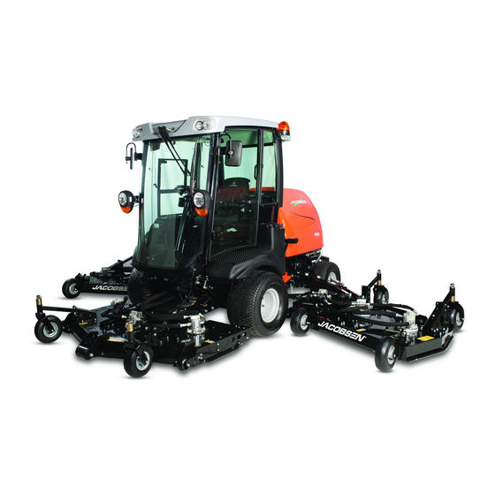
HR800
™
Rotary Mower
461311G01 – Kubota
462411G01 – Kubota
WARNING
Warning: If incorrectly used, this machine can
cause severe injury. Those who use and maintain
this machine should be trained in its proper use,
warned of its dangers, and must read the entire
manual before attempting to set up, operate, adjust,
or service the machine.
GB
®
V3307-CR-T-E4B with 2 Post ROPS
®
V3307-CR-T-E4B with Cab
4372606-Rev B
When Performance Matters.
™
Advertisement
Table of Contents

Related Manuals for Jacobsen HR800


Summary of Contents for Jacobsen HR800
- Page 1 4372606-Rev B Safety, Operation, & Maintenance Manual HR800 ™ Rotary Mower ® 461311G01 – Kubota V3307-CR-T-E4B with 2 Post ROPS ® 462411G01 – Kubota V3307-CR-T-E4B with Cab WARNING Warning: If incorrectly used, this machine can cause severe injury. Those who use and maintain...
- Page 2 FOREWORD This manual contains adjustment, maintenance, and Before you operate your machine, you and each operator troubleshooting instructions for your new Jacobsen you employ should read the manual carefully in its machine. This manual should be stored with the entirety.
-
Page 3: Table Of Contents
Introduction 7.10 Fuel System..............85 7.11 Air Cleaner..............86 1.1 Important................3 7.12 Battery ................87 1.2 Product Identification ............4 7.13 Charge The Battery ............88 1.3 Guidelines For The Disposal Of Scrap Products ....6 7.14 Engine Exhaust............... 88 1.4 parts manual ............... -
Page 4: Introduction
1Introduction IMPORTANT ______________________________________________________________ The HR800 with Diesel engine is a self propelled rotary mower. With hydraulic systems to power the traction drive, the cutting unit lift and lower, the cutting unit drives and the steering. IMPORTANT: Do the maintenance indicated in this manual to make sure that the quality of cut is kept at a high level. -
Page 5: Product Identification
® 1451 MARVIN GRIFFIN RD, AUGUSTA, GA, U.S.A. Mowers with CE 1-800-848-1636 (US) PRODUCT OF THE U.S.A. WWW.JACOBSEN.COM Option Location of Mower Serial number plate The serial number plate (A) is found on the front of the chassis, between the front deck stops next to the environmental noise decal (B). - Page 6 THIS ROPS MEETS THE REQUIREMENTS OF ISO 21299-2009 For Product IT HAS BEEN DESIGNED TO BE FITTED TO JACOBSEN HR800 SERIES MOWING MACHINES WITH A MAXIMUM VEHICLE Serial Number WEIGHT OF 5000 POUNDS OR 2268 Kg. THIS DECAL MUST BE KEPT...
-
Page 7: Guidelines For The Disposal Of Scrap Products
Some parts are not easily separated e.g Hydraulic hose. These materials must be added to the “General discarded materials” area. • Do not burn discarded materials. Change the machinery records to show that the machine is not in operation and is discarded. Supply this serial number to The Jacobsen Warranty Department to close their records. en-6... -
Page 8: Parts Manual
Website – www.jacobsen.com. Select the “ONLINE PARTS LOOK-UP” tab. These pages will show the parts list and the line drawings you need to help with the identification of spare parts. Website – www.jacobsen.com. Select the “MANUALS” tab. You have the option to view or “Download” a PDF version of the parts manual. -
Page 9: Safety 2
Manuals in additional languages may be available on the Jacobsen or RansomesJacobsen website. Read all of the instructions for this mower carefully. Know the controls and the correct operation of the equipment. - Page 10 2 SAFETY Inspect the cutting system before you start the mower. Make sure the blades are free to rotate. When you rotate one blade, other blades can rotate. 2.1.3 OPERATION Never operate the engine without enough ventilation or in an enclosed area. The carbon monoxide in the exhaust fumes can increase to dangerous levels.
- Page 11 ROPS. Do not remove the ROPS from the mower. Jacobsen must approve any changes to the ROPS. 2.1.5 SAFE HANDLING OF FUELS The fuel and the fuel vapors are flammable. Use caution when you add the fuel to the mower. The fuel vapors can cause an explosion.
- Page 12 Keep all nuts, bolts and screws tight to make sure the equipment is in safe condition. Replace worn or damaged parts for safety. Replace damaged or worn labels. Only use parts, accessories and attachments approved by Jacobsen. To decrease the fire hazard, remove materials that burn from the engine, muffler, battery tray and fuel tank area.
- Page 13 By following all instructions in this manual, you increase the life of your machine and keep its maximum performance. Adjustments and maintenance must always be done by an approved technician. If additional information or service is needed, contact your Authorized Jacobsen Dealer. Your Dealer knows the current methods to service this equipment.
- Page 14 2006/42/EC Sections 3.2.2, Seating & 3.4.3, Rollover. (ANSI B71.4-2012 section 20.7) Jacobsen recommends that the owner/user of the machine completes a local risk assessment of the machine to find any conditions that do not follow this rule. e.g. when you drive the machine next to water or on the highway.
- Page 15 SAFETY 2 WARNING Vibration Exposure Limits Exposure limits are calculated as a combination of the vibration level (magnitude) of the tool and the Daily Exposure Time (Trigger Time). E.g. A product with 5m/s² vibration can be used up to 2 hours/day to reach the EAV and up to 8 hours/day to reach the ELV.
-
Page 16: Labels
3 LABELS 3Labels SAFETY LABELS__________________________________________________________ 4324674 4170640 4153197 18°+ 4321506 en-15... - Page 17 LABELS 3 009034920 Caution, Stay Away From Hot Surfaces. 009034880 Caution, fan blade, do not open or remove the safety shields while the engine is in operation. 009034900 Caution, drive belt, do not remove the safety shields while the engine is in operation. 4324674 Caution, Low Sulfur Diesel Fuel.
-
Page 18: Instruction Labels
3 LABELS INSTRUCTION LABELS TOTAL EQUIVIS ZS 46 CLASSIFICATION CJ-4 1-2-3 1-2-3 25 MM 1.0 IN 25 MM 1.0 IN 28 MM 1.5 IN 28 MM 1.5 IN 50 MM 2.0 IN 50 MM 2.0 IN 63 MM 2.5 IN 63 MM 2.5 IN 76 MM... - Page 19 LABELS 3 Description 009034770 Guaranteed Sound Power Level 4286422 Hydraulic Fluid 009039870 Jack & Hook Point 164580 Lubrication Point 4316686 Engine Oil Classification 4355986 Height Of Cut - Wing deck 4359126 Height Of Cut - Front Deck en-18...
-
Page 20: Controls
4 CONTROLS 4Controls OPERATOR COMPARTMENT _______________________________________________ 6.10 6.10 en-19... -
Page 21: Control Panel
CONTROLS 4 CONTROL PANEL _________________________________________________________ 4.2.18 4.2.17 Mowers with Cab 4.2.19 4.2.16 4.2.14 4.2.21 4.2.15 4.2.2 4.2.13 4.2.20 4.2.6 4.2.4 4.2.5 4.2.10 4.2.11 Mowers with 2 Post ROPS 4.2.4 4.2.6 4.2.5 4.2.7 4.2.23 4.2.22 4.2.2 4.2.10 4.2.11 4.2.12 4.2.22 4.2.8 4.2.21 4.2.9 4.2.23... - Page 22 4 CONTROLS 4.2.1 STARTER KEY SWITCH ____________________________________________________ Turn the starter key to the right to the 'start' position to start the engine. When the engine starts, release the key and allow to return automatically to the 'on' position to run. NOTE.
- Page 23 CONTROLS 4 4.2.5 MOW SWITCH ____________________________________________________________ The mow switch engages mow speed and cutter rotation. To cut grass, push the front of the switch and move the joysticks forward to lower the decks. When engaged the yellow LED on the pod is illuminated. To stop the blade, push the rear of the rocker switch.
- Page 24 4 CONTROLS 4.2.8 DPF SWITCH _____________________________________________________________ With the switch in the center position (default) it allows automatic Active Regen. Operation of the mower is not changed during Active Regen. See 8.15 When the Regen Request light flashes, press and release the front part of the switch to start the Parked Regen cycle.
- Page 25 CONTROLS 4 4.2.12 ROTATING BEACON ______________________________________________________ Operates the vehicles rotating beacon when a cab is not fitted. 4.2.13,14,15 LIFT/LOWER SWITCHES ______________________________________________ 4.2.13. Right Hand Wing Cutter Deck 4.2.15 4.2.14 4.2.14 Front Cutter Deck 4.2.13 4.2.15 Left Hand Wing Cutter Deck To lower the cutting unit move the switch lever forward.
- Page 26 4 CONTROLS 4.2.20 WEIGHT TRANSFER BUTTON ______________________________________________ The button will transfer weight by the hydraulic system between the drive wheels and the cutter deck. To adjust the amount of weight transfer manually on the lift valve. See section 7.2. 4.2.21 HORN __________________________________________________________________ The horn button is on the control panel.
- Page 27 CONTROLS 4 4.2.23.2 WARNING / SERVICE SCREEN ____________________________________________ After the startup screen the warning screen is shown, the screen is visible for four seconds. If the machine is within 5 hours of the next service, a warning is shown. An operator input is needed to continue to the main screen.
- Page 28 4 CONTROLS 4.2.23.3 FIRST SCREEN _________________________________________________________ This screen shows the mow switch in the OFF position, the transport lock engaged, the TST is in operation and speed mode set to creep. the MODE button the transmission mode can be changed By pressing between Automatic, Manual and Creep.
- Page 29 CONTROLS 4 4.2.23.5 THE ENGINE WILL NOT START ____________________________________________ When the ignition key is turned to the start position this screen is shown. If any of the following flash. • The parking brake is not applied. • The mow switch is not in the OFF position. •...
- Page 30 4 CONTROLS 4.2.23.8 TIME DISPLAY OPTION __________________________________________________ This display shows the time and engine hours. This display shows the date and engine hours. Button 2 toggles between the two options. MODE 4.2.23.9 MAIN MENU SELECT ____________________________________________________ Use the button below the to access the main menu.
- Page 31 CONTROLS 4 4.2.23.11 DATE SELECT _________________________________________________________ Press the button and the day is underlined. Press the button up and down to move the count. C l o c k S e t t i n g s Press the button to accept and move to the month (underlined).
- Page 32 4 CONTROLS SERVICE MENU Please note some functions require a PIN to access. 4.2.23.14 SERVICE MENU _______________________________________________________ button accepts the option that has the is moved with the up and down to select, fault log, time until service, diagnostics, I/O diagnostics and ECU (engine Control Unit) monitor.
- Page 33 CONTROLS 4 4.2.23.17 FAULT LOG DETAIL ____________________________________________________ Select the fault log to be accessed and accept to show the details. These details show the date and time of the fault. F a u l t l o g Press the button to return to previous menu.
- Page 34 4 CONTROLS 4.2.23.20 DIAGNOSTICS_________________________________________________________ Water Temp [deg C] = 60.5 Fuel Level [pct] = 100 D i a g n o s t i c s Sys Voltage [V] = 11.8 Wa t e r Te m p [ d e g C ] = 6 0 . 5 F u e l L e v e l [ p c t ] = 1 0 0 Cutter [h] = S y s Vo l t a g e [ V ] = 11 .
- Page 35 CONTROLS 4 4.2.23.23 CONNECTOR J2 _______________________________________________________ This screen shows the status of the J2 connectors. Press the left side button to return to I/O diagnostics menu. Connector J2 J2-1 Right Lower On and OFF shown for illustration purposes only. J2-2 Right Lift J2-3 Center Lift J2-4 High Speed Sol J2-5 Left Lower...
- Page 36 4 CONTROLS 4.2.23.26 CONNECTOR J5 _______________________________________________________ This screen shows the status of the J5 connectors. Press the left side button to return to I/O diagnostics menu. Connector J5 J5-1 Center Deck LED Output On and OFF shown for illustration purposes only. J5-2 Left Mow Solenoid J5-3 Deck Lock Solenoid (3,4) J5-4 Center Mow Solenoid...
- Page 37 CONTROLS 4 4.2.23.29 SERVICE MANAGER PIN INPUT __________________________________________ Press the button up and down to change the numbers. Select . to accept. Insert PIN Initial PIN number is 1001 0 0 0 0 Note. Service managers are advise to change the pin to stop the machine parameters being changed to an dangerous condition.
- Page 38 4 CONTROLS 4.2.23.32 INFORMATION SCREEN TWO ____________________________________________ This screen displays, engine-total fuel used (liter) engine fuel rate (l/h). Press the button up and down to move between screen one and two. Engine Total Fuel used Engine Fuel Rate litre Drive Engine Torque DSF Soot SETTINGS MENU Please note some functions require a PIN to access.
- Page 39 CONTROLS 4 4.2.23.35 MEASURE UNITS MENU _________________________________________________ Select the measure units and accept S e t t i n g s M e n u M o d e M e a s u r e U n i t s P I N 4.2.23.36 MEASURE UNITS_______________________________________________________ ...
- Page 40 4 CONTROLS 4.2.23.37 PIN MENU ____________________________________________________________ Select the PIN menu and accept S e t t i n g s M e n u M o d e M e a s u r e U n i t s P I N 4.2.23.38 INPUT PIN ____________________________________________________________ Press the button...
- Page 41 CONTROLS 4 4.2.23.40 CRUISE SELECT _______________________________________________________ Select between “mow mode, not enabled”, “mow and transport mode” or “transport mode” use button up and down to move between them. Press the button .to accept C r u i s e M e n u M o w M o d e N o t E n a b l e d Press the button...
- Page 42 4 CONTROLS 4.2.23.43 VEHICLE SPEED _______________________________________________________ Select the vehicle speed and accept P i n M e n u C r u i s e C o n t r o l C r o s s C u t Ve h i c l e S p e e d Change PIN Inclinometer...
- Page 43 CONTROLS 4 4.2.23.46 INCLINOMETER ________________________________________________________ Select to shows TST status, Enabled or Disabled. Press the button up and down to move P i n M e n u TST Setting between Enabled or Disabled Select . To C r u i s e C o n t r o l TST Status Not Fitted C r o s s C u t accept.
- Page 44 4 CONTROLS 4.2.23.49 FAN DRIVE ___________________________________________________________ Select the Fan Drive and accept The normal fan operation is based on engine temperature. Fan speed will increase as P i n M e n u F a n D r i v e M e n u engine temperature increases.
- Page 45 CONTROLS 4 4.2.23.51 LANGUAGE MENU _____________________________________________________ Select the language and accept On the page for the language options, Press the button to select, press the button L a n g u a g e M a i n M e n u ...
- Page 46 4 CONTROLS 4.2.23.54 WARNING SLOPE ANGLE - INHIBIT CUT___________________________________ If the slope angle reaches 21° the screen will display this warning indicating that at 21° the front cutter deck will be lifted and held above the ground to improve the stability and all cutting units will stop rotation.
- Page 47 CONTROLS 4 4.2.23.57 WARNING ENGINE FAULT _______________________________________________ When this screen is shown, there is an engine fault.Stop the engine as soon as possible and contact your service dealer. When this fault occurs the machine go’s into limp-home mode. Press the button below the to confirm the fault.
- Page 48 4 CONTROLS 4.2.23.60 WARNING CHARGE FILTER BLOCKED ____________________________________ When this screen is shown, the hydraulic-charge filter is blocked and needs replacing. Replace the filter element at the earliest opportunity to avoid possible hydraulic system damage. Press the button below the to confirm the fault.
- Page 49 CONTROLS 4 4.2.23.63 WARNING SOLENOID FAULT ____________________________________________ When this screen is shown, there is a hydraulic circuit solenoid fault. Go to i/o diagnostics for solenoid identification. Press the button below the to confirm the fault. FAULT SOLENOID 4.2.23.64 WARNING (TST) TILT SENSOR TECHNOLOGY FAULT________________________ When this screen is shown, there is a fault with the TST.
-
Page 50: Traction Pedal
4 CONTROLS TRACTION PEDAL ________________________________________________________ The traction pedal is found on the right side of the footplate. • Carefully press the top (A) of the foot pedal to reach the forward speed that you need. • To stop - Carefully return the foot pedal to the Neutral position. •... -
Page 51: Seat Right-Side Armrest And Pod
CONTROLS 4 SEAT RIGHT-SIDE ARMREST AND POD _______________________________________ The right-side armrest of the seat carries the control pod. The Control Pod position is adjustable, as shown, to give a good position for the operation of the controls. Release the hand wheel (A). To lift or lower the armrest, use two hands. -
Page 52: Tow Valve
4 CONTROLS TOW VALVE ______________________________________________________________ The Tow valve is situated on the right hand side of the transmission pump. To push the machine, disengage the parking brake, see section 5.8 Turn screw (A) located on the right side of the transmission pump three complete turns counterclockwise. -
Page 53: Cab Controls
CONTROLS 4 CAB CONTROLS __________________________________________________________ Left Turn Signal Working Lights Switch (Optional) Beacon Switch Front Screen De-Frost / De-Mist Switch Rear Screen Wiper Switch (Optional) Front Screen Wash Switch Front Screen Wiper Switch Right Turn Signal Fan Control Air Conditioning Control Temperature Control Fuse Holder Fuse Holder... -
Page 54: Operation
5 OPERATION 5Operation DAILY INSPECTION _______________________________________________________ CAUTION The inspection must be done each day when the engine is turned off and all fluids are cold. Lower the cutting units to the ground, engage the parking brake, stop the engine and remove the ignition key. Do a visual inspection of the mower. -
Page 55: Interlock System
OPERATION 5 INTERLOCK SYSTEM ______________________________________________________ The Interlock System prevents the engine to start unless the operator is in the seat, the parking brake is engaged and the mow switch is in the OFF position. The system stops the engine if the operator leaves the seat with the mow switch in the ON position or the parking brake disengaged. -
Page 56: Operating Procedure
5 OPERATION OPERATING PROCEDURE __________________________________________________ WARNING This mower has a Roll Over Protection Structure (ROPS). Always wear the seat belt. If the mower is over turning, hold the steering wheel. Do not try to move off the mower or leave the seat. CAUTION To prevent injury, always wear safety glasses, leather work shoes or boots, a hard hat and ear protection. -
Page 57: Starting The Engine
OPERATION 5 STARTING THE ENGINE ____________________________________________________ Start the engine with the operator in the seat, the mow switch (A) in the OFF position and the parking brake switch (B) in the ON position. Remove your foot from the traction pedal. Always wear the seat belt. Set the throttle control (C) to half throttle. -
Page 58: Driving
5 OPERATION DRIVING _________________________________________________________________ Read and follow all safety instructions contained in this manual when you drive the mower. When you operate in the reverse direction, look behind you to make sure you have a clear path. IMPORTANT: Equipment must meet the current regulations to be driven on the public roads. To transport the mower, move the mow switch to the OFF position, lift the cutting units to the transport position and move the transport lock switch to the ON position. -
Page 59: To Remove A Blockage From Cutting Units
OPERATION 5 TO REMOVE A BLOCKAGE FROM CUTTING UNITS _____________________________ Stop and lift the cutter decks before you move the machine to level ground. Engage the transport locks. Turn off the engine and remove the ignition key. If the front cutter deck has become blocked, you will need to tilt front cutter deck refer to section 8.19 Wear the personal protective equipment that is applicable for this work, for example eye protection, gloves and correct footwear. -
Page 60: Mowing On Slopes
5 OPERATION 5.10 MOWING ON SLOPES______________________________________________________ The mower is designed for good traction and stability in normal conditions for operation. On wet grass slopes use caution, as wet grass decreases traction and steering control. WARNING To decrease the possible cause of overturning. The safest method for operation on slopes and terraces is. - Page 61 ROPS to comply with the Machinery Directive 2006/42/EC Sections 3.2.2, Seating & 3.4.3, Rollover Jacobsen recommends that a local risk assessment is completed by the owner/user of the machine to determine the risks associated with working on slopes.
- Page 62 5 OPERATION Height (C) Result (D) Inches with 1 Yard Level (A) Millimeters with 1 Meter Level (A) Slope in Degrees Slope Grade % 10.0 16.7 11.3 20.0 11.8 20.8 12.7 22.5 25.0 15.4 27.5 15.5 27.8 16.7 30.0 17.0 30.6 18.0 32.5...
-
Page 63: Towing The Mower
OPERATION 5 5.11 TOWING THE MOWER______________________________________________________ The machine is fitted with tie-down loops front and rear. Always tie down the machine securely to the trailer. Always follow any recommendations for maximum trailer weights given in your towing vehicles handbook. IMPORTANT Use the chart in the specification section 11.2 to calculate the total weight of your machine configuration. -
Page 64: Adjustments
Always use the jack stands. A qualified technician must always do adjustments and maintenance. If the correct adjustments can not be made, contact your Jacobsen Dealer. Inspect the equipment according to the maintenance schedule and keep complete records. Keep the equipment clean. -
Page 65: Weight Transfer Adjustment
ADJUSTMENTS 6 WEIGHT TRANSFER ADJUSTMENT __________________________________________ The weight transfer bias can be adjusted on the lift valve. The valve is accessible by removing the access panel in the operator platform. The valve is situated on the right hand side. To adjust: Loosen the locknut A while holding the threaded shaft still with the Allen Key B. -
Page 66: Height Of Cut Adjustment
6 ADJUSTMENTS HEIGHT OF CUT ADJUSTMENT______________________________________________ The cutting height is determined by the position of the blades in relation to the caster wheels. Changes to this height are made at all points and can be made in any order. Make adjustment selections for each deck from the height of cut chart for that deck included in this section. -
Page 67: Height Of Cut Adjustment (Wing Cutter Deck)
ADJUSTMENTS 6 HEIGHT OF CUT ADJUSTMENT (WING CUTTER DECK) __________________________ Raise the deck to mid position. Engage transport lock Remove the quick pin (A) from the top of the caster wheel pivot spindle Remove the caster wheel from caster support (B). Select either Position 1 or Position 2 for wheel mounting bracket (C). -
Page 68: General Instructions For Grammer Seats
6 ADJUSTMENTS GENERAL INSTRUCTIONS FOR GRAMMER SEATS _____________________________ All The seat adjustments are to be done while the vehicle is stopped. • After removal of the backrest cover, hold the backrest frame in position with a support before the backrest adjuster is operated. -
Page 69: Air Suspension Seat (Grammer Msg95 -721)
ADJUSTMENTS 6 6.10 AIR SUSPENSION SEAT (GRAMMER MSG95 -721) ______________________________ 6.10.1 WEIGHT ADJUSTMENT ____________________________________________________ The seat should be adjusted for the driver's weight with the driver sitting on the seat. The adjustment is made by pulling out or pushing in the actuator lever (1) until the green marking is visible in the weight-and-height indicator (2). - Page 70 6 ADJUSTMENTS 6.10.5 ARMRESTS ADJUSTMENT (OPTION) ________________________________________ The inclination of the armrests can be modified by turning the adjustment knob (arrow). 6.10.6 ARMREST (OPTION) ______________________________________________________ The armrests can be folded up if required and the height individually adjusted. To adjust the armrests for height, separate the round cap (see arrow) from the cover, loosen the hexagon nut (size 13mm) and adjust the armrest to the desired position and tighten the nut again.
- Page 71 ADJUSTMENTS 6 6.10.9 BACKREST ADJUSTMENT (OPTION)_________________________________________ The backrest is adjusted using the locking lever (arrow). • The locking lever must latch into the desired position. It should not be possible to move the backrest into another position when it is locked. 6.10.10 FORE / AFT ISOLATOR (OPTION)___________________________________________ Under certain driving conditions (for example with a trailer attached), it is useful to activate the fore/aft isolator.
- Page 72 6 ADJUSTMENTS 6.10.13 ABSORBER (OPTION) ____________________________________________________ The absorber setting of the seat can be varied to suit the on and off-road driving conditions. The cushioning effect can be individually adjusted for this purpose. Turn the lever to the desired position and release soft hard 6.10.14 MAINTENANCE _________________________________________________________...
-
Page 73: Torque Specification
Jacobsen uses Grade 5 (Inch) and Grade 8.8 (Metric) Plated bolts, unless a note is given. Always check the marks on the head of the bolts for the bolt grade. For tightening plated bolts, use the value given for lubricated. -
Page 74: Maintenance And Lubrication
20.00 x 10.00 - 8 Grassmaster 8pr (16 psi) (30 psi) 1.24 bar 2.21 bar HR800 with Cab 26.5 x 14.00 - 12 Ultra Chevron 6pr 20.00 x 10.00 - 8 Grassmaster 8pr (18 psi) (32 psi) 1.38-1.72 bar Caster Wheels... - Page 75 MAINTENANCE AND LUBRICATION 7 en-74...
- Page 76 7 MAINTENANCE AND LUBRICATION Engine Service Interval Chart Interval Item Section Daily Check Engine Oil Level. 10 hours Check Fuel Level. Check Coolant Level. Check Fan Belt Tension. Check Fuel Pipes and Clamps. Every 50 hours ...
- Page 77 MAINTENANCE AND LUBRICATION 7 Interval Item Section Replace Oil Separator Related Rubber Piping. Replace DPF Related Rubber Piping. Replace Intake Air Line and Suction Air Pressure takeout Rubber Piping. Replace Boost Sensor Pressure Rubber Piping. Replace EGR Cooler Rubber Piping.
-
Page 78: General Precautions
50 hours of a new engine can make a difference to the performance and life of the engine. During the first 50 hours of operation, Jacobsen recommends the following. • Allow the engine to reach a temperature of at least 60° C (140° F) before operation at full load. -
Page 79: Engine Lubrication
MAINTENANCE AND LUBRICATION 7 ENGINE LUBRICATION _____________________________________________________ Check Engine Oil Level Check the engine oil level before you start or at least five minutes after you stop the engine. Park the machine on level ground, remove the dipstick (A), clean with a cloth and replace in position. -
Page 80: Engine Coolant
Check and tighten the engine fan belt (see maintenance chart) and replace the belt (see maintenance chart). Replace the clamps and hoses (see maintenance chart). Have your Jacobsen Dealer check the cooling system if you need to add coolant more than one time a month or you add more than a liter of coolant at a time. - Page 81 MAINTENANCE AND LUBRICATION 7 Check The Engine Coolant Level The level of coolant in a cold expansion tank must be between the indicators. If you need to fill the tank, remove the plastic cap and fill with the correct anti-freeze mixture (See Section 7.1). Replace the plastic cap.
-
Page 82: Hydraulic System
7 MAINTENANCE AND LUBRICATION HYDRAULIC SYSTEM ______________________________________________________ Drain and replace the hydraulic oil if one of the following occur. • Component failure • Water or foam is in the hydraulic fluid • The hydraulic fluid has a rancid odor (indication of high heat) •... -
Page 83: Hydraulic Filter
MAINTENANCE AND LUBRICATION 7 HYDRAULIC FILTER _______________________________________________________ The hydraulic system is protected by two 10 micron filters. Flow through the filter is monitored while you operate the mower. When the difference in hydraulic pressure across the filter is greater than 16 to 20 psi (1.1 to 1.4 BAR), the hydraulic oil filter warning will be shown on the display. -
Page 84: Hydraulic Test Ports
7 MAINTENANCE AND LUBRICATION HYDRAULIC TEST PORTS __________________________________________________ If you have any problems with the hydraulic system, check the hydraulic pressures with the service ports that are supplied. All tests must be done with the hydraulic oil at the normal temperature of the engine, unless specified at a different temperature. -
Page 85: Fuel
MAINTENANCE AND LUBRICATION 7 FUEL ____________________________________________________________________ Diesel fuel is flammable. Use caution when you add the fuel to the mower. Only use an approved container. The spout on the container must fit inside the fuel filler neck. Never use the containers that are not approved to keep or transfer fuel. -
Page 86: Fuel System
7 MAINTENANCE AND LUBRICATION 7.10 FUEL SYSTEM ____________________________________________________________ Use Diesel to B.S. EN590 or ASTM D975 (Ultra Low Sulfur) Water Separator If the water is not removed from the fuel, damage to the fuel-injection system can occur. When the fuel filter light on the filter light module is illuminated or at service interval, drain the water from the water separator. -
Page 87: Air Cleaner
MAINTENANCE AND LUBRICATION 7 7.11 AIR CLEANER ____________________________________________________________ Check the service indicator (1) each day. If the red band become visible in the window (2), replace the filter elements. Do not remove the elements to inspect or clean. Removal of the filter that is not necessary increases the risk of dust and other particles to enter the engine. -
Page 88: Battery
7 MAINTENANCE AND LUBRICATION 7.12 BATTERY ________________________________________________________________ Before you service the battery, make sure the ignition switch is in the OFF position and the key is removed. CAUTION When you service the battery, always use the tools with insulation, wear protective glasses and protective clothing. -
Page 89: Charge The Battery
MAINTENANCE AND LUBRICATION 7 7.13 CHARGE THE BATTERY __________________________________________________________ WARNING Charge the battery in an area with good airflow. The battery can release hydrogen gas that is explosive. To prevent an explosion, keep any device that can cause sparks or flames away from the battery. When the battery charger is turned on, to prevent injury, stay away from the battery. -
Page 90: Diesel Particulate Filter
7 MAINTENANCE AND LUBRICATION 7.15 DIESEL PARTICULATE FILTER ______________________________________________ During the operation of the mower, the level of particle material will increase in the Diesel Particulate Filter (DPF) system. The periodic Regen of the DPF system is needed to remove particle material. During an Active or Parked Regen, the engine will use more fuel. -
Page 91: Hydraulic Hoses
MAINTENANCE AND LUBRICATION 7 7.16 HYDRAULIC HOSES ______________________________________________________________ WARNING To prevent injury from the hot, high pressure oil, never use your hands to check for oil leaks. Use the paper or cardboard to find leaks. The hydraulic fluid pressure can have enough force to enter your skin. If hydraulic fluid has entered your skin, a doctor must remove the hydraulic fluid surgically within a few hours or gangrene can occur. -
Page 92: Tires
7 MAINTENANCE AND LUBRICATION 7.17 TIRES ___________________________________________________________________ Keep the tires correctly inflated to increase tire life. Inspect the tread wear. Check the tire pressure each day, while the tires are cool. Use an accurate low-pressure tire gauge. Keep tires inflated at the correct pressure (See Section 7.1) CAUTION DO NOT try to put a tire on a rim unless you have the correct training, tools and experience. -
Page 93: Blade Change
MAINTENANCE AND LUBRICATION 7 7.19 BLADE CHANGE __________________________________________________________ Front Cutter Deck Raise the deck to the cross cut position. This will allow the setting pin D to lift clear of the arm and be easier to remove. Remove the pins at position D on both sides of the machine which lock the deck in its working position. -
Page 94: Inspecting Blades
7 MAINTENANCE AND LUBRICATION 7.20 INSPECTING BLADES _____________________________________________________ Inspected the blade in accordance with the maintenance chart or when the cutting unit is removed from the mower, carefully inspect the blades to make sure the blades are in good condition (A). Replace any blade that has bends (B), grooves (C) or cracks (D). CAUTION Be careful when you check blades to prevent pinching hands and fingers between ends of the blades. -
Page 95: Folding Rops
This instruction is given to meet: The machinery directive, 2006/42/EC Sections 3.2.2, Seating & 3.4.3, Rollover. Jacobsen. recommend that the owner operator of the machine complete a local risk assessment on the machine to find any conditions that do not follow this rule. -
Page 96: Care And Cleaning
Clean all plastic or rubber parts with a weak soap solution or use commercially available rubber cleaners. To keep the original high polish of the plastic parts, wax with a good grade of one-step cleaner wax. Repair damaged metal surfaces and use Jacobsen touch-up paint. Apply wax to the equipment for maximum paint protection. -
Page 97: Mower Storage
MAINTENANCE AND LUBRICATION 7 7.24 MOWER STORAGE ________________________________________________________ General • Clean the mower and lubricate. Repair and paint damaged or open metal. • Inspect the mower, tighten all hardware, replace worn or damaged components. • Drain and fill the radiator. •... -
Page 98: Lubrication Of Cutting Unit
7 MAINTENANCE AND LUBRICATION 7.25 LUBRICATION OF CUTTING UNIT ____________________________________________ Wing Pivot Arm (A) Front Pivot Arm (B) Caster Wheel Mounting Pivot (C) en-97... -
Page 99: Problem Solving 8
PROBLEM SOLVING 8 8Problem Solving ENGINE PROBLEM SOLVING ________________________________________________ The Engine is difficult to start Cause Action Check the fuel tank and fuel filter. The fuel is thick and does not flow. Remove any contamination from the fuel system. Clean the fuel filter with kerosene. The fuel system is a pressure type. - Page 100 8 PROBLEM SOLVING Dirty Smoke or carbon increase on the Exhaust Cause Action Wrong fuel Only use Diesel fuel specified in specification section. Bad Nozzle If necessary, replace the nozzle. Engine must be stopped immediately Cause Action The color of The exhaust turns dark. Check the fuel system and the fuel injection nozzle.
-
Page 101: Quality Of Cut 9
QUALITY OF CUT 9 9Quality of Cut QUALITY OF CUT PROBLEM SOLVING________________________________________ Make a “test cut” to check the performance of the mower before you start the repairs. This area must have turf conditions that are known and do not change across the area. This type of area allows an accurate inspection of the performance of the mower to be made. -
Page 102: Step Cutting
9 QUALITY OF CUT STEP CUTTING ___________________________________________________________ Step cutting occurs when grass is cut higher on one side of a cutting unit than the other side. Step cutting can occur when one cutting unit is higher than another cutting unit. The wear of mechanical parts or an incorrect roller adjustment can cause step cutting. -
Page 103: Scalping
QUALITY OF CUT 9 SCALPING _______________________________________________________________ Scalping is a condition in which areas of grass are cut shorter than the adjacent areas. The area can be light green or brown. A low HOC setting or turf that is not level can cause scalping. -
Page 104: Stragglers
9 QUALITY OF CUT STRAGGLERS ____________________________________________________________ Stragglers are separated blades of grass the are not cut, or are cut incorrectly. TN0223 NOTE: Arrow indicates direction of travel. Probable Cause Remedy Edge of the cutting blade(s) are not sharp. Sharpen the blade(s). See Section 7.21 Cut (ground) speed is higher than normal Reduce the cut (ground) speed. -
Page 105: Streaks
QUALITY OF CUT 9 STREAKS ________________________________________________________________ A streak is a line of grass that is not cut. The cause of a streak can be a damaged blade. TN0224 NOTE: Arrow indicates direction of travel. Probable Cause Remedy Damaged blade(s). Replace the blade(s). See Section 7.19 The mower turns at a rate that is faster than the mower Turn at a speed that will allow the cutting units to overlap. -
Page 106: Windrowing
9 QUALITY OF CUT WINDROWING ____________________________________________________________ Windrowing is the deposit of clippings increased at one end of cutting unit(s) or between cutting units. Windrowing can make a line in the direction of travel. TN0225 NOTE: Arrow indicates direction of travel. Probable Cause Remedy The grass is higher than the level at which the mower... -
Page 107: Mismatched Cutting Units
QUALITY OF CUT 9 MISMATCHED CUTTING UNITS ______________________________________________ Mismatched cutting units is a pattern of different cutting heights, that gives the grass a stepped cut appearance. This appearance is normally because of a mismatched HOC (height-of-cut) adjustment from one cutting unit to another unit. -
Page 108: Fuses Relays And Controller
10 FUSES RELAYS AND CONTROLLER 10Fuses Relays and Controller 10.1 FUSE AND RELAY/COMPONENT IDENTIFICATION______________________________ en-107... - Page 109 FUSES RELAYS AND CONTROLLER 10 FUSES FUSE HOLDER 1 Fuse Rating Protected Circuits Key Switch to Beacon And Horn Key Switch to Proximity Switches and Pressure Switches Key Switch to Accessory Sockets Key Switch to Machine Control Unit Key Switch to Air Seat Key Switch to Mow Switch FUSE HOLDER 2 Fuse...
-
Page 110: Specifications
11 SPECIFICATIONS 11Specifications 11.1 ENGINE SPECIFICATION ___________________________________________________ Model: V3307-CR-TE4 Type: Vertical, water-cooled, 4-cycle diesel engine Number of Cylinders Bore and Stroke 94mm x 120mm (3.70 in. x 4.72 in.) Total Displacement 3.331 liters (148.53 cu.in.) Combustion Type Direct Injection SAE Net Intermittent kW / rpm 55.4 kW @ 2600 rpm H.P. -
Page 111: Dimensions & Weights
Uncut Turning Circle With 167.6 cm (66 inch) Wing Cutter Decks 0 cm 0 in. Weight Of HR800 Machine With ROPS, No Decks And Fuel Tank Empty 1686 kg 3716 lb. Weight Of HR800 Machine With Cab, Air Conditioning, No Decks And 1885 kg 4155 lb. - Page 112 11 SPECIFICATIONS HR800 with ROPS Right deck not shown HR800 with Cab Right deck not shown en-111...
-
Page 113: Machine Specification
11.3 MACHINE SPECIFICATION __________________________________________________ Frame construction: Heavy duty steel chassis with formed steel frame rails. Cutter Deck Drive: HR800, Nine individual hydraulic motors with self lubricating integral bearings. Transmission: Hydrostatic closed loop parallel cross series SureTrac system. Variable displacement piston pump. -
Page 114: Vibration
Information Supplied for Physical Agents Directive 2002/44/EC By reference to: Hand/Arm Standards: BS EN ISO 5349-1 (2001) BS EN ISO 5349-2 (2002) 70543 with ROPS 70543 with Cab HR800 HR800 Hand / Arm Acceleration Maximum Accelerations m/s² Hand / Arm Acceleration Maximum Accelerations m/s²... -
Page 115: Noise
SPECIFICATIONS 11 11.5 NOISE ___________________________________________________________________ When the machine was tested for sound pressure (Operator Ear). The Machinery Safety Directive 2006/42/EC Exposure Of Workers To The Risks Arising From Physical Agents (Noise) Directive 2003/10/EC By compliance to: The Lawnmower Standard BS EN ISO 5395:2013 Sound Pressure Standard EN ISO 3746: 2010 ROPS machine: Measured Sound Pressure 85 dB(A) ±... -
Page 116: Cutter Deck Specification
11 SPECIFICATIONS 11.8 CUTTER DECK SPECIFICATION _____________________________________________ Product HR800 Front Deck Deck Width 183 cm (72 inch) Deck (Front) Bull nose profile, steel construction. Solid bumper rails, bolted assembly of all impact and Construction wearing parts. Blade Length 635 mm (25 inch) -
Page 117: Recommended Lubricants
Jacobsen for U.S. sales and distribution. Communications, including ordering, pricing and terms should be made directly with the listed suppliers. Jacobsen makes no warranty or commitment with regard to the functionality, reliability, or safety of these third-party products. Jacobsen does support warranty for the equipment when the approved accessories are mounted. -
Page 118: Declaration Of Conformity
Maschinenbezeichnung ▪ Ονομασία μηχανήματος ▪ Gépnév ▪ Denominazione della macchina ▪ Iekārtas nosaukums ▪ Mašinos pavadinimas ▪ HR800 with 2 Post ROPS Option Isem tal-Magna ▪ Nazwa urządzenia ▪ Nome da Máquina ▪ Numele echipamentului ▪ Názov stroja ▪ Naziv stroja ▪ Nombre de la máquina ▪... - Page 119 SPECIFICATIONS 11 Conformity Assessment Procedure (Noise) ▪ Оценка за съответствие на процедурата (Шум) ▪ Postup hodnocení plnění podmínek (hluk) ▪ Procedure for overensstemmelsesvurdering (Støj) ▪ Procedure van de conformiteitsbeoordeling (geluid) ▪ Vastavushindamismenetlus (müra) ▪ Vaatimustenmukaisuuden arviointimenettely (Melu) ▪ Procédure d’évaluation de conformité (bruit) ▪ Konformitätsbeurteilungsverfahren (Geräusch) ▪ Διαδικασία...
- Page 120 Director of Engineering κατέχει την τεχνική έκθεση και έχει την εξουσιοδότηση να ταξινομήσει τον τεχνικό φάκελο και ο οποίος είναι διορισμένος στην Κοινότητα. Ransomes Jacobsen Limited A gyártó nevében meghatalmazott személy, akinek jogában áll módosítania a nyilatkozatot, a műszaki West Road, Ransomes Europark, dokumentációt őrzi, engedéllyel rendelkezik a műszaki fájl összeállításához, és aki a közösségben letelepedett személy.
- Page 121 NOTES 12 12Notes en-120...
- Page 122 A worldwide dealer network and factory trained technicians backed by Genuine Jacobsen Parts provide reliable, high-quality product support. When Performance Matters. ™ Textron Specialized Vehicles 1451 Marvin Griffin Rd, Augusta, GA 30906 www.Jacobsen.com 800-848-1636...
Need help?
Do you have a question about the HR800 and is the answer not in the manual?
Questions and answers