Jacobsen Ransomes HR 6010 Service Course Manual
Hide thumbs
Also See for Ransomes HR 6010:
- Parts and maintenance manual (142 pages) ,
- Operator's manual (10 pages) ,
- Operator's manual (25 pages)
Table of Contents
Advertisement
®
Service Course Manual
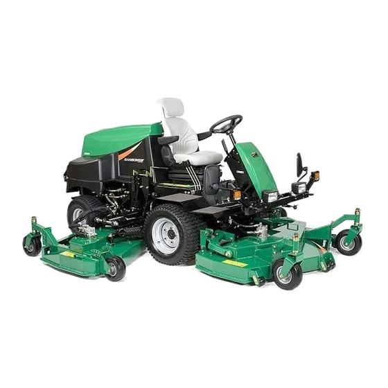
HR 6010
Serial Range: EA
WARNING: If incorrectly used this machine can cause severe
injury. Those who use and maintain this machine should be
trained in its proper use, warned of its dangers and should
read the entire manual before attempting to set up, operate,
adjust or service the machine.
G B
Advertisement
Table of Contents

Related Manuals for Jacobsen Ransomes HR 6010


Summary of Contents for Jacobsen Ransomes HR 6010
- Page 1 ® Service Course Manual HR 6010 Serial Range: EA WARNING: If incorrectly used this machine can cause severe injury. Those who use and maintain this machine should be trained in its proper use, warned of its dangers and should read the entire manual before attempting to set up, operate, adjust or service the machine.
-
Page 3: Table Of Contents
INDEX SPECIFICATION CONTROLS ENGINE STEERING WHEELS & TYRES HYDRAULICS ELECTRICAL SYSTEM PREVENTATIVE MAINTENANCE OPTIONS NOTES... -
Page 5: Introduction Section
SECTION 1 INTRODUCTION Machine Specifications... - Page 7 ENGINE SPECIFICATION Hydraulic Tank Capacity: 18.8 litres TYPE: Perkins 45KW @ 2800 RPM, Battery: Exide 065 4 cylinder (in line) vertical Diesel engine, 4 stroke, water DIMENSIONS cooled, 2200cc with 12V electric start. Width of cut: Model: 404C-22T 295cm Model 2.95 metres Maximum Speed: 2800 +0/-50 RPM (No...
-
Page 9: Controls
SECTION 2 Controls Contols Control Description... -
Page 10: Engine
Controls STARTER KEY SWITCH The starter key (A) should be turned clockwise to the 'pre-heat' (No. 2) position to heat the glowplugs when the green warning lamp goes out, on warning lamp display module, turn the starter key clockwise to the 'start' (No. 3) position to start the engine. After starting, the key should be released and allowed to return automatically to the 'on' (No. -
Page 11: Steering
Controls TRANSPORT LATCHES When transporting the machine ensure the cutting decks are raised and the transport latches (A) are engaged. PARKING BRAKE The parking brake (B) is engaged when the lever is moved toward the operator. The brake is fitted with a micro switch that senses brake position. - Page 12 Controls HYDRAULIC LIFT LEVERS The cutting units can be raised and lowered by three control levers (A,B,C) situated on the right hand side of the operators seat and can be operated as follows: Centre lever controls Centre Cutting Deck. Right hand lever controls R.H. Cutting Deck.
-
Page 13: Hydraulics
Controls INSTRUMENT PANEL ENGINE PREHEAT INDICATOR LAMP Colour green, on when the ignition switch is turned clockwise to the pre-heat position. Once the lamp goes out the engine can be started. ENGINE TEMPERATURE GAUGE Indicates current temperature of engine, whilst running. HYDRAULIC OIL WARNING LAMP Colour red, on when the hydraulic oil temperature reaches a preset level. - Page 14 Controls HOURMETER Located on the left hand side of the steering tower, above the parking brake. (A) Records engine running hours. HORN The horn is an audible alarm for the following situations: a) Horn (A) sounds continuously-this indicates a high engine coolant temperature condition.
-
Page 15: Height Of Cut Adjustment
HEIGHT OF CUT ADJUSTMENT The cutting height is determined by the position of the blades in relation to the caster wheels. Changes to this height are made at (4) points and can be made in any order. Make adjustment selections for each deck from the height of cut chart for that deck included in this section. - Page 16 HEIGHT OF CUT ADJUSTMENT (WING DECKS) The cutting height is determined by the position of the blades in relation to the caster wheels. Changes to this height are made at (4) points and can be made in any order. Make selections for each adjustment below from the accompanying height of cut charts .
- Page 17 SECTION 3 Engine Engine specifications Engine Routing Servicing...
-
Page 18: Engine Specification
Engine Specification TYPE: Perkins 45KW @ 2800 RPM, 4 cylinder (in line) vertical Diesel engine, 4 stroke, water cooled, 2200cc with 12V electric start. Model: 404C-22T Maximum Speed:2800 +0/-50 RPM (No load) Idle Speed: 1250 ± 50 RPM Oil Sump Capacity:10.6 litres Fuel: No. - Page 19 ENGINE: First 50 working hours and every 250 working hours. Change Engine Oil. Warm up the engine first and then shut it off. Remove oil drain plug from the bottom of the crankcase and wipe it off. Replace the drain plug and fill engine with 10.6 litres of oil (with filter).
- Page 20 Coolant Change Completely drain the cooling water from the radiator and flush the cooling system with flushing deter gent. Drainplugs A. Check for leaks or loose connec tions at the radiator, cylinder head gasket, etc. Open screw valve B fully. Fill cooling system with recom mended water / antifreeze to the Fig.15...
- Page 21 SECTION 4 STEERING This section has been left blank...
- Page 23 SECTION 5 WHEELS AND TYRES Front Wheel Assembly Rear Axle and Wheel Assembly...
-
Page 24: Options
Front Wheel Assembly Wheel nut torque setting 92 Nm (68 Lbs Ft) Tyre Size - 24 X 13.00 - 12 Tyre Type - Maxxis tread pattern (Kevlar Option) C-165S 4pr Tyre Pressure - 20 psi (1.37 bar) Tyre Pressure (Kevlar) - 20-22 psi (1.37-1.5 bar) -
Page 25: Rear Axle Assembly
Rear Axle Assembly REAR WHEEL TOE-IN The rear wheels should have 1/8" (3.2mm) toe-in from the front of the wheel to the back of the wheel. Adjust as follows: 1. Loosen locknuts N at balljoints near both rear wheels. 2. Rotate the tie rod O until wheels are correctly positioned. - Page 27 SECTION 6 HYDRAULICS Hydraulic Servicing and Components Hydraulic Schematics 1 - Steering to one side & lift levers in different positions 2 - All deck lowered and cutting 3 - Forward drive, transport speed 4 - Forward drive engage diff-loc 5 - Reverse drive Tools required:Standard automotive hand tools, including torque wrench, seal drivers, circlip pliers and bearing driver.
- Page 28 Steering to one side and Lift levers in different positions P S Cylinder Reservoir W/T VARIABLE PRESSURE Filter Head STEERING PRESSURE CHARGE P S Valve SUCTION Inlet Manifold 921 psi DRAIN To Steering Wheel Steering & Lift Pump 18 Lpm CV 2 RV 1 Front cutter...
- Page 29 Reservoir W/T VARIABLE PRESSURE STEERING PRESSURE Filter Head CHARGE SUCTION DRAIN Inlet Manifold Deck Outputs RV 1 = 40 Lpm 3045 psi (Engine at 2800rpm) RV 2 LH Cutter 300 psi Deck Motor Wing Deck CV 2 Valves RV 2 300 psi RV 1 Front cutter...
- Page 30 Forward drive Transport speed Side brake Valve Front brake Valve Oil from steering valve "L" port RH Front LH Front wheelmotor wheelmotor Check Valve 280cc 280cc Oil returning from; front deck circuit Check Valve 40 lpm Cooler Filter Servo Piston 38.9 lpm Tank: Shell Tellus 46...
- Page 31 Forward drive Engage diff-lock Side brake Valve Front brake Valve Oil from steering valve "L" port RH Front LH Front wheelmotor wheelmotor Check Valve 280cc 280cc Oil returning from; front deck circuit Check Valve 40 lpm Cooler Filter Servo Piston 38.9 lpm Tank: Shell Tellus 46...
- Page 32 Reverse drive Side brake Valve Front brake Valve Oil from steering valve "L" port RH Front LH Front wheelmotor wheelmotor Check Valve 280cc 280cc Oil returning from; front deck circuit Check Valve 40 lpm Cooler Filter Servo Piston 38.9 lpm Tank: Shell Tellus 46 LH Rear wheelmotor...
- Page 33 SECTION 7 ELECTRICAL SYSTEM Electric components Electrical schematics 1 - Master 2 - Hot 3 - Pre-Heat 4 - Ignition 5 - Engine Start 6 - Operator in seat, brake off 7 - Energise For/Rev pedal 8 - Energise cutter deck switch 9 - Lower decks 10 - Depress deck enable switch 11 - Deck running and diff-loc engaged...
- Page 34 FUSE POSITIONS - MAIN FUSES MAIN FUSES The main fuse panel is situated under the front of the engine bonnet . Fuse A - 40Amp Link Fuse - System Fuse. Fuse B - 40Amp Link Fuse - Glow Plug and Accessory Fuse.
- Page 35 RELAY POSITIONS Relays are situated under the front tower cover Relay A - Flasher Relay Relay B - RH Deck Relay Relay C - Centre Deck Relay Relay D - LH Deck Relay Relay E - 4 Wheel Drive Relay Relay F - Start Relay Relay G - Horn Relay Relay H - Alarm Relay...
- Page 36 MASTER 1 of 2 CUTTING DECK SW LAMP SPLIT TO MAIN #1 CUTTING DECK SWITCH OPTIONAL BEACON SWITCH BEACON LAMP BEACON SWITCH CONNECTOR SPLIT TO MAIN #2 GLOW IND'R LAMP FUEL GAUGE BATTERY LAMP OIL TEMP 511-192 LAMP HAZARD SWITCH TEMP GAUGE OIL PRESS...
- Page 37 FLASHER UNIT FRONT LAMPS GROUND RH IND MASTER 2 of 2 RH REAR LT RH SIDE LH IND LH SIDE RH IND BRAKE LTS LH IND LH REAR LT LH MAIN RH MAIN FRONT SPLIT TO LAMPS REAR LIGHTS FUSE HOLDER 10 AMP 10 AMP BRAKE LTS...
- Page 38 Hot 1 of 2 CUTTING DECK SW LAMP SPLIT TO MAIN #1 CUTTING DECK SWITCH OPTIONAL BEACON SWITCH BEACON LAMP BEACON SWITCH CONNECTOR SPLIT TO MAIN #2 GLOW IND'R LAMP FUEL GAUGE BATTERY LAMP OIL TEMP 511-192 LAMP HAZARD SWITCH TEMP GAUGE OIL PRESS...
- Page 39 FLASHER UNIT FRONT LAMPS GROUND RH IND Hot 2 of 2 RH REAR LT RH SIDE LH IND LH SIDE RH IND BRAKE LTS LH IND LH REAR LT LH MAIN RH MAIN FRONT SPLIT TO LAMPS REAR LIGHTS FUSE HOLDER 10 AMP 10 AMP BRAKE LTS...
- Page 40 Engine Pre-Heat 1 of 2 CUTTING DECK SW LAMP SPLIT TO MAIN #1 CUTTING DECK SWITCH OPTIONAL BEACON SWITCH BEACON LAMP BEACON SWITCH CONNECTOR SPLIT TO MAIN #2 GLOW IND'R LAMP FUEL GAUGE BATTERY LAMP OIL TEMP 511-192 LAMP HAZARD SWITCH TEMP OIL PRESS...
- Page 41 FLASHER UNIT FRONT LAMPS GROUND RH IND Engine Pre-Heat 2 of 2 RH REAR LT RH SIDE LH IND LH SIDE RH IND BRAKE LTS LH IND LH REAR LT LH MAIN RH MAIN FRONT SPLIT TO LAMPS REAR LIGHTS FUSE HOLDER 10 AMP 10 AMP...
- Page 42 Ignition Switch ON 1 of 2 CUTTING DECK SW LAMP SPLIT TO MAIN #1 CUTTING DECK SWITCH OPTIONAL BEACON SWITCH BEACON LAMP BEACON SWITCH CONNECTOR SPLIT TO MAIN #2 GLOW IND'R LAMP FUEL GAUGE BATTERY LAMP OIL TEMP 511-192 LAMP HAZARD SWITCH TEMP...
- Page 43 FLASHER UNIT FRONT LAMPS GROUND RH IND Ignition Switch ON 2 of 2 RH REAR LT RH SIDE LH IND LH SIDE RH IND BRAKE LTS LH IND LH REAR LT LH MAIN RH MAIN FRONT SPLIT TO LAMPS REAR LIGHTS FUSE HOLDER 10 AMP 10 AMP...
- Page 44 Start Engine 1 of 2 CUTTING DECK SW LAMP SPLIT TO MAIN #1 CUTTING DECK SWITCH OPTIONAL BEACON SWITCH BEACON LAMP BEACON SWITCH CONNECTOR SPLIT TO MAIN #2 GLOW IND'R LAMP FUEL GAUGE BATTERY LAMP OIL TEMP 511-192 LAMP HAZARD SWITCH TEMP GAUGE...
- Page 45 FLASHER UNIT FRONT LAMPS GROUND RH IND Start Engine 2 of 2 RH REAR LT RH SIDE LH IND LH SIDE RH IND BRAKE LTS LH IND LH REAR LT LH MAIN RH MAIN FRONT SPLIT TO LAMPS REAR LIGHTS FUSE HOLDER 10 AMP 10 AMP...
- Page 46 Operator In Seat, Brake Off 1 of 2 CUTTING DECK SW LAMP SPLIT TO MAIN #1 CUTTING DECK SWITCH OPTIONAL BEACON SWITCH BEACON LAMP BEACON SWITCH CONNECTOR SPLIT TO MAIN #2 GLOW IND'R LAMP FUEL GAUGE BATTERY LAMP OIL TEMP 511-192 LAMP HAZARD...
- Page 47 FLASHER UNIT FRONT LAMPS GROUND RH IND Operator In Seat, Brake Off 2 of 2 RH REAR LT RH SIDE LH IND LH SIDE RH IND BRAKE LTS LH IND LH REAR LT LH MAIN RH MAIN FRONT SPLIT TO LAMPS REAR LIGHTS FUSE HOLDER...
- Page 48 Energise Fwd/Rev Pedal Switch 1 of 2 CUTTING DECK SW LAMP SPLIT TO MAIN #1 CUTTING DECK SWITCH OPTIONAL BEACON SWITCH BEACON LAMP BEACON SWITCH CONNECTOR SPLIT TO MAIN #2 GLOW IND'R LAMP FUEL GAUGE BATTERY LAMP OIL TEMP 511-192 LAMP HAZARD SWITCH...
- Page 49 FLASHER UNIT FRONT LAMPS GROUND RH IND Energise Fwd/Rev Pedal Switch 2 of 2 RH REAR LT RH SIDE LH IND LH SIDE RH IND BRAKE LTS LH IND LH REAR LT LH MAIN RH MAIN FRONT SPLIT TO LAMPS REAR LIGHTS FUSE HOLDER 10 AMP...
- Page 50 Energise Cutter Deck Switch 1 of 2 CUTTING DECK SW LAMP SPLIT TO MAIN #1 CUTTING DECK SWITCH OPTIONAL BEACON SWITCH BEACON LAMP BEACON SWITCH CONNECTOR SPLIT TO MAIN #2 GLOW IND'R LAMP FUEL GAUGE BATTERY LAMP OIL TEMP 511-192 LAMP HAZARD SWITCH...
- Page 51 FLASHER UNIT FRONT LAMPS GROUND RH IND Energise Cutter Deck Switch 2 of 2 RH REAR LT RH SIDE LH IND LH SIDE RH IND BRAKE LTS LH IND LH REAR LT LH MAIN RH MAIN FRONT SPLIT TO LAMPS REAR LIGHTS FUSE HOLDER 10 AMP...
- Page 52 Lower Decks 1 of 2 CUTTING DECK SW LAMP SPLIT TO MAIN #1 CUTTING DECK SWITCH OPTIONAL BEACON SWITCH BEACON LAMP BEACON SWITCH CONNECTOR SPLIT TO MAIN #2 GLOW IND'R LAMP FUEL GAUGE BATTERY LAMP OIL TEMP 511-192 LAMP HAZARD SWITCH TEMP GAUGE...
- Page 53 FLASHER UNIT FRONT LAMPS GROUND RH IND Lower Decks 2 of 2 RH REAR LT RH SIDE LH IND LH SIDE RH IND BRAKE LTS LH IND LH REAR LT LH MAIN RH MAIN FRONT SPLIT TO LAMPS REAR LIGHTS FUSE HOLDER 10 AMP 10 AMP...
- Page 54 Depress Deck Enable Switch 1 of 2 CUTTING DECK SW LAMP SPLIT TO MAIN #1 CUTTING DECK SWITCH OPTIONAL BEACON SWITCH BEACON LAMP BEACON SWITCH CONNECTOR SPLIT TO MAIN #2 GLOW IND'R LAMP FUEL GAUGE BATTERY LAMP OIL TEMP 511-192 LAMP HAZARD SWITCH...
- Page 55 FLASHER UNIT FRONT LAMPS GROUND RH IND Depress Deck Enable Switch 2 of 2 RH REAR LT RH SIDE LH IND LH SIDE RH IND BRAKE LTS LH IND LH REAR LT LH MAIN RH MAIN FRONT SPLIT TO LAMPS REAR LIGHTS FUSE HOLDER 10 AMP...
- Page 56 Decks Running & Diff-Lock Depressed 1 of 2 CUTTING DECK SW LAMP SPLIT TO MAIN #1 CUTTING DECK SWITCH OPTIONAL BEACON SWITCH BEACON LAMP BEACON SWITCH CONNECTOR SPLIT TO MAIN #2 GLOW IND'R LAMP FUEL GAUGE BATTERY LAMP OIL TEMP 511-192 LAMP HAZARD...
- Page 57 FLASHER UNIT FRONT LAMPS GROUND RH IND Decks Running & Diff-Lock Depressed 2 of 2 RH REAR LT RH SIDE LH IND LH SIDE RH IND BRAKE LTS LH IND LH REAR LT LH MAIN RH MAIN FRONT SPLIT TO LAMPS REAR LIGHTS FUSE HOLDER...
- Page 59 SECTION 8 PREVENTATIVE MAINTENANCE Lubrication chart Maintenance chart...
- Page 60 LUBRICATION AND MAINTENANCE RANSOMES HR6010 Series: EA MAINTENANCE AND PARTS MANUAL LUBRICATION Fig.3 ! ! ! ! ! Lubricate every 40 working hours at arrows FLUID REQUIREMENTS QUANTITY TYPE ENGINE OIL 10.6 Litres 10W 30 (SE/SF/SG) (with filter) HYDRAULIC OIL 37.0 Litres Shell T ellus 46 (with filter)
-
Page 61: Lubrication And Maintenance Chart
RANSOMES HR6010 Series: EA LUBRICATION AND MAINTENANCE MAINTENANCE AND PARTS MANUAL LUBRICATION AND MAINTENANCE CHART B la c k b u lle t p o in ts a re o p e ra to r c h e c k s a n d w h ite b u lle t p o in ts a re w o rk s h o p m a in te n a n c e p ro c e d u re s F irs t E v e ry E v e ry... -
Page 62: Cutter Deck Adjustments
CUTTER DECK ADJUSTMENTS CUTTER DECK BELT TENSION Check all belts regularly during the first 5, 10 and 15 hours of operation, and then after every 50 hours of operation. If necessary adjust as follows: CENTER DECK 1. Adjust belt tension to 1/2” (13 mm) deflection at 10 lbs (5 kg) force at the middle of the long rear span D. -
Page 63: Notes
CUTTER DECK ADJUSTMENTS BLADE SHARPENING & REMOVAL When required, the cutter blades may be sharpened either by filing or grinding. It is essential that the balance of the blades are maintained. NOTE: Always replace blades with original Ransomes blades, do not use another manu- facturers blades. -
Page 65: Section 9 Options
SECTION 9 OPTIONS Options List: LMAB 612 - Wing Decks for 2.95m width of cut LMAB 680 - Wing Decks for 3.23m width of cut 970028 - Antiscalp kit for wing decks LMAC 120 - Lighting kit - left hand dipped 970018 - ROPS, 2 post with seat belt 500450001 - 4 post ROPS... - Page 66 SECTION 10 NOTES...
- Page 67 NOTES...
- Page 68 NOTES...
- Page 69 NOTES...
- Page 70 NOTES...
- Page 71 NOTES...
- Page 72 NOTES...
- Page 73 NOTES...
- Page 74 NOTES...
- Page 75 NOTES...
Need help?
Do you have a question about the Ransomes HR 6010 and is the answer not in the manual?
Questions and answers