SMA STP 33-US-41 User Manual
Sunny tripower core1-us
Hide thumbs
Also See for STP 33-US-41:
- Replacement manual (252 pages) ,
- Manual (212 pages) ,
- Replacement manual (50 pages)

Related Manuals for SMA STP 33-US-41


Summary of Contents for SMA STP 33-US-41
- Page 1 User Manual SUNNY TRIPOWER CORE1-US STP 33-US-41 / STP 50-US-41 / STP 62-US-41 W E R R I P O N Y T S U N ENGLISH STP33-62-US-41-BA-en-11 | Version 1.1...
- Page 2 SMA Solar Technology AG Legal Provisions The information contained in these documents is the property of SMA Solar Technology AG. No part of this document may be reproduced, stored in a retrieval system, or transmitted, in any form or by any means, be it electronic, mechanical, photographic, magnetic or otherwise, without the prior written permission of SMA Solar Technology AG.
-
Page 3: Table Of Contents
SMA Solar Technology AG Table of Contents Table of Contents Information on this Document..........Validity ........................Target Group......................Content and Structure of this Document ..............Levels of Warning Messages ..................Symbols in the Document ..................Typographical Elements in the Document .............. - Page 4 Table of Contents SMA Solar Technology AG 4.15 Changing the Operating Mode of the Multifunction Relay ........37 4.16 Configuring the Modbus Function................38 4.17 Setting SMA ShadeFix....................39 4.18 Generating the I-V Characteristic Curve ..............39 4.19 Activating or Deactivating the Arc-Fault Circuit Interrupter (AFCI) ......40 4.20...
-
Page 5: Information On This Document
You will find the latest version of this document and further information on the product in PDF format and as eManual at www.SMA-Solar.com. You can also call up the eManual via the user interface of the product. -
Page 6: Symbols In The Document
[Key] • Placeholder for variable • Parameter WCtlHz.Hz# components (e.g., parameter names) Designations in the Document Complete designation Designation in this document Sunny Tripower CORE1-US Inverter, product Additional Information For more information, please go to www.SMA-Solar.com. STP33-62-US-41-BA-en-11 User Manual... - Page 7 Information about how to activate and to set the grid supporting fea- tures according to UL 1741 SA "Efficiency and Derating" Technical Information Efficiency and derating behavior of the SMA inverters "Short-Circuit Currents" Technical Information Information on short-circuit currents of SMA PV inverters "Parameters and Measured Values"...
-
Page 8: Safety
Any other application may cause personal injury or property damage. Alterations to the SMA products, e.g., changes or modifications, are only permitted with the express written permission of SMA Solar Technology AG. Unauthorized alterations will void guarantee and warranty claims and in most cases terminate the operating license. -
Page 9: Important Safety Instructions
SMA Solar Technology AG 2 Safety IMPORTANT SAFETY INSTRUCTIONS Keep the manual for future reference. This section contains safety information that must be observed at all times when working. The product has been designed and tested in accordance with international safety requirements. As with all electrical or electronical devices, there are residual risks despite careful construction. - Page 10 2 Safety SMA Solar Technology AG DANGER Danger to life due to electric shock in case of overvoltages and if surge protection is missing Overvoltages (e. g. in the event of a flash of lightning) can be further conducted into the building and to other connected devices in the same network via the network cables or other data cables if there is no surge protection.
- Page 11 SMA Solar Technology AG 2 Safety WARNING Danger to life due to electric shock from destruction of the measuring device due to overvoltage Overvoltage can damage a measuring device and result in voltage being present in the enclosure of the measuring device. Touching the live enclosure of the measuring device results in death or lethal injuries due to electric shock.
- Page 12 Sunny Portal or the use of FTP push. High costs for the Internet connection can be the result. • SMA Solar Technology AG recommends using an Internet flat rate. NOTICE Damage to the product due to cleaning agents The use of cleaning agents may cause damage to the product and its components.
-
Page 13: Product Overview
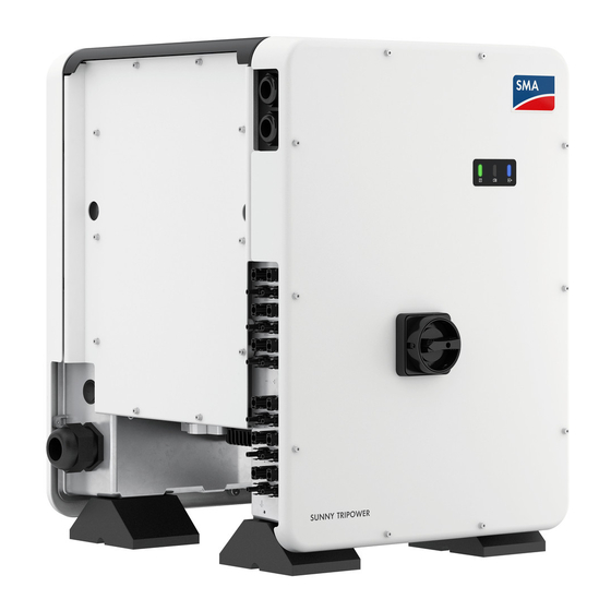
SMA Solar Technology AG 3 Product Overview Product Overview Product Description Figure 1: Design of the product Position Designation Cover AC Connection Unit DC Connection Unit LEDs The LEDs indicate the operating state of the product. Cable glands for data cables... -
Page 14: Symbols On The Product
3 Product Overview SMA Solar Technology AG Position Designation Type label The type label clearly identifies the product. The type label must remain permanently attached to the product. You will find the following informa- tion on the type label: • Device type (Model) •... -
Page 15: Interfaces And Functions
PV array can be detected at an early stage. SMA Speedwire The product is equipped with SMA Speedwire as standard. SMA Speedwire is a type of communication based on the Ethernet standard. SMA Speedwire is designed for a data transfer rate of 100 Mbps and enables optimum communication between Speedwire devices within systems. - Page 16 The product is equipped with a Modbus interface. The Modbus interface is deactivated by default and must be configured as needed. The Modbus interface of the supported SMA products is designed for industrial use – via SCADA systems, for example – and has the following tasks: •...
- Page 17 The SMA Sensor Module has different interfaces for connecting various sensors (i.e. temperature sensor, irradiation sensor, anemometer or energy meter). The SMA Sensor Module converts the signals of the connected sensors and transmits them to the inverter. The SMA Sensor Module can be retrofitted.
- Page 18 With SMA ShadeFix, inverters use the best possible energy supply from the PV modules at all times to increase yields in shaded systems. SMA ShadeFix is enabled by default. The time interval of SMA ShadeFix is usually six minutes. This means that the inverter determines the optimum operating point every six minutes.
-
Page 19: Led Signals
SMA Smart Connected SMA Smart Connected is the free monitoring of the product via the SMA Sunny Portal. Thanks to SMA Smart Connected, the operator and qualified person will be informed automatically and proactively about product events that occur. - Page 20 If an event occurs, a distinct event message and the corresponding event number will be displayed in addition on the product user inter- face or in the communication product (e.g. SMA Data Manager). The blue LED flashes slowly Communication connection is being established for approx.
-
Page 21: Operation
☐ The respective latest version of one of the following web browsers must be installed: Chrome, Edge, Firefox or Safari. ☐ The SMA Grid Guard code of the Installer must be available for the changing of grid-relevant settings after completion of the first ten feed-in hours or installation assistant (see "Application for SMA Grid Guard Code"... - Page 22 ☐ JavaScript must be enabled in the web browser of the end device. ☐ The SMA Grid Guard code of the Installer must be available for the changing of grid-relevant settings after completion of the first ten feed-in hours or installation assistant (see "Application for SMA Grid Guard Code"...
-
Page 23: Establishing A Connection Via Ethernet In The Local Network
☐ The respective latest version of one of the following web browsers must be installed: Chrome, Edge, Firefox or Safari. ☐ The SMA Grid Guard code of the Installer must be available for the changing of grid-relevant settings after completion of the first ten feed-in hours or installation assistant (see "Application for SMA Grid Guard Code"... -
Page 24: Establishing A Connection Via Wlan In The Local Network
☐ The respective latest version of one of the following web browsers must be installed: Chrome, Edge, Firefox or Safari. ☐ The SMA Grid Guard code of the Installer must be available for the changing of grid-relevant settings after completion of the first ten feed-in hours or installation assistant (see "Application for SMA Grid Guard Code"... - Page 25 4. Click on Save. 5. In the New password field, enter a password for the Installer user group. Assign a uniform password to all SMA devices to be registered in a system. The installer password is also the system password.
- Page 26 4 Operation SMA Solar Technology AG Log Out as the User or Installer 1. On the right-hand side of the menu bar, select the menu User Settings. 2. In the subsequent context menu, select [Logout]. ☑ The login page of the user interface opens. The logout was successful.
-
Page 27: Start Page Design Of The User Interface
SMA Solar Technology AG 4 Operation Start Page Design of the User Interface Figure 2: Design of the user interface's home page (example) User Manual STP33-62-US-41-BA-en-11... - Page 28 • Starting the installation assistant • SMA Grid Guard login • Logout Help Provides the following functions: • Displaying information on Open Source licenses used • Link to the website of SMA Solar Technology AG STP33-62-US-41-BA-en-11 User Manual...
- Page 29 SMA Solar Technology AG 4 Operation Position Designation Description Status bar Displays the following information: • Inverter serial number • Inverter firmware version • IP address of the inverter within the local network and/or IP address of the inverter during WLAN connection •...
-
Page 30: Displaying And Downloading The Stored Data
4 Operation SMA Solar Technology AG Displaying and Downloading the Stored Data If an external storage device is plugged in, you can display and download the stored data. Procedure: 1. Activate the user interface (see Section 4.1, page 21). 2. Log into the user interface (see Section 4.2, page 24). -
Page 31: Starting The Installation Assistant
Requirement: ☐ When configuring after completion of the first ten feed-in hours or after exiting the installation assistant, the SMA Grid Guard code must be available in order to change the grid-relevant parameters (see "Application for SMA Grid Guard Code" at www.SMA-Solar.com). Procedure: 1. -
Page 32: Activate Wps Function
4 Operation SMA Solar Technology AG Activate WPS Function The WPS function can be used for different purposes: • Automatic connection to a network (e.g. via router) • Direct connection between the product and an end device Depending on the intended application of the WPS function, the procedure for activation will vary. -
Page 33: Switching The Dynamic Power Display Off
SMA Solar Technology AG 4 Operation Switching WLAN Off If you would like to switch the WLAN function off completely, you must switch off both the direct connection and the connection in the local network. Procedure: • To switch off the direct connection in the parameter group PV system communication >... -
Page 34: Changing The Password
3. Call up the menu Device Parameters. 4. Click on [Edit parameters]. 5. Log in using the SMA Grid Guard code to change those parameters designated by a lock (only for installers): • Select the menu User Settings (see Section 4.3, page 27). -
Page 35: Configuring The Country Data Set
SMA Solar Technology AG 4 Operation • Enter the SMA Grid Guard code and select [Login]. 6. Expand the parameter group that contains the parameter which is to be configured. 7. Change the desired parameters. 8. Select [Save all] to save the changes. -
Page 36: Configuring The Rapid Shutdown Function
4 Operation SMA Solar Technology AG 4. Select [Save and continue] after each step up until the step Grid management service. 5. Make the settings as described in the following. Make the settings for systems with external setpoint 1. In the tab Active power mode set the switch Active power setpoint to [On]. -
Page 37: Changing The Operating Mode Of The Multifunction Relay
SMA Solar Technology AG 4 Operation 3. On the right-hand side of the menu bar, select the menu User Settings (see Section 4.3 "Start Page Design of the User Interface", page 27). 4. In the context menu, select [Starting the installation assistant]. -
Page 38: Configuring The Modbus Function
The Modbus interface is deactivated by default and the communication ports 502 set. ® ® ® In order to access SMA invertes with SMA Modbus or SunSpec Modbus , the Modbus interface must be activated. After activating the interface, the communication ports of both IP protocols can be changed. -
Page 39: Setting Sma Shadefix
Section 4.11 "Changing Operating Parameters", page 34). Procedure: • In the parameter group DC-side > DC settings > SMA ShadeFix, set the parameter Time interval of SMA ShadeFix and set the required time interval. The ideal time interval is usually six minutes. This value should only be increased if the shading situation changes extremely slowly. -
Page 40: Activating Or Deactivating The Arc-Fault Circuit Interrupter (Afci)
4 Operation SMA Solar Technology AG 2. Click on Diagnosis in the menu. 3. Select the required MPP tracker. 4. Click on [Start new measurement]. 5. Go to [PDF export] or [CSV export] to export the data shown. 4.19 Activating or Deactivating the Arc-Fault Circuit... -
Page 41: Saving The Configuration In A File
Requirements: ☐ Changes to grid-relevant parameters must be approved by the responsible grid operator. ☐ The SMA Grid Guard code must be available (see "Application for SMA Grid Guard Code" at www.SMA-Solar.com). Procedure: 1. Open the user interface (see Section 4.1, page 21). - Page 42 The update file is, for example, available for download on the product page of the inverter at www.SMA-Solar.com. Ensure that only the update file to which the inverter is to be updated must be stored on the USB flash drive.
- Page 43 Connection Unit (see the inverter installation manual). 7. Pull the USB flash drive out of the USB port. 8. Commission the inverter (see inverter manual at www.SMA-Solar.com). 9. Call up the user interface of the inverter and check the events to see whether a firmware update has been successfully completed.
-
Page 44: Clean The Product
5 Clean the product SMA Solar Technology AG Clean the product NOTICE Damage to the product due to cleaning agents The use of cleaning agents may cause damage to the product and its components. • Clean the product and all its components only with a cloth moistened with clear water. -
Page 45: Troubleshooting
Installer is the same as the system password in the communication product. Procedure: 1. Request PUK (application form available at www.SMA-Solar.com). 2. Open the user interface (see Section 4.1, page 21). 3. Enter the PUK instead of the password into the field Password. -
Page 46: Event Messages
6 Troubleshooting SMA Solar Technology AG Event Messages Event number Message, cause and corrective measures Grid incident The grid voltage or grid impedance at the connection point of the inverter is too high. The inverter has disconnected from the utility grid. - Page 47 SMA Solar Technology AG 6 Troubleshooting Event number Message, cause and corrective measures Grid incident The power frequency is not within the permissible range. The inverter has dis- connected from the utility grid. Corrective measures: • If possible, check the power frequency and observe how often fluctuations occur.
- Page 48 6 Troubleshooting SMA Solar Technology AG Event number Message, cause and corrective measures Grounding connection missing > Check connection The grounding conductor is not correctly connected. Corrective measures: • Ensure that the grounding conductor is correctly connected. 3401 3402 DC overvoltage > Disconnect PV array 3404 Overvoltage at the DC input.
- Page 49 SMA Solar Technology AG 6 Troubleshooting Event number Message, cause and corrective measures 3801 3802 DC overcurrent > Check PV array 3803 Overcurrent at the DC input. The inverter briefly interrupts feed-in operation. 3805 Corrective measures: 3806 • If this message is displayed frequently, ensure that the PV array has been 3807 correctly rated and wired.
- Page 50 Parameters could not be set using the memory card. The inverter continues to feed in. Corrective measures: • Ensure that the parameters are set correctly. • Ensure that you have an SMA Grid Guard code. 7106 Update file defective The update file is defective. The update failed. The inverter continues to feed...
- Page 51 SMA Solar Technology AG 6 Troubleshooting Event number Message, cause and corrective measures 7320 The device was successfully updated The firmware update was completed successfully. 7330 Condition test failed The testing of the update conditions was not successful. The firmware update package is not suitable for this inverter.
- Page 52 6 Troubleshooting SMA Solar Technology AG Event number Message, cause and corrective measures 7348 Incorrect file format The configuration file is not of the required format or is damaged. Corrective measures: • Ensure that the selected configuration file is of the required format and is not damaged.
- Page 53 Ethernet. 7622 No communication with the I/O module This event is displayed during a device-internal communication error with the SMA I/O Module. The inverter will disconnect from the utility grid for safety reasons. 7702 Device fault The cause must be determined by the Service.
- Page 54 Service. Corrective measures: • Contact the Service. 9002 SMA Grid Guard code invalid The SMA Grid Guard code entered is incorrect. The operating parameters are still protected and cannot be changed. Corrective measures: • Enter the correct SMA Grid Guard code. STP33-62-US-41-BA-en-11...
- Page 55 9003 Grid parameters locked Changes to the grid parameters are now blocked. In order to be able to make changes to the grid parameters, from now on you must log in using the SMA Grid Guard code. 9005 Changing of grid parameters not possible > Ensure DC supply This error can have the following causes: •...
- Page 56 6 Troubleshooting SMA Solar Technology AG Event number Message, cause and corrective measures 9034 Error in Rapid Shutdown System This message can have the following causes: • The Rapid Shutdown Function was not correctly configured. • The PV array could not be correctly disconnected. Voltage can be applied to the DC inputs of the inverter.
- Page 57 SMA Solar Technology AG 6 Troubleshooting Event number Message, cause and corrective measures 10110 Time synchronization failed: [xx] No time information could be called up from the set NTP server. Corrective measures: • Ensure that the NTP server was configured correctly.
- Page 58 6 Troubleshooting SMA Solar Technology AG Event number Message, cause and corrective measures 10251 [Interface]: communication status goes to [OK / Warning / Error / Not connected] The communication status to the network switch or DHCP server (router) has changed. An additional error message may be displayed.
- Page 59 SMA Solar Technology AG 6 Troubleshooting Event number Message, cause and corrective measures 10255 [Interface]: Network load OK The network load has returned to a normal range after being busy. 10282 [User group]-Login via [protocol] locked After several incorrect login attempts, login has been blocked for a limited time.
- Page 60 6 Troubleshooting SMA Solar Technology AG Event number Message, cause and corrective measures 10286 Wi-Fi connection lost The inverter has lost Wi-Fi connection to the selected network. Corrective measures: • Ensure that the Wi-Fi router or Wi-Fi access point is still active.
-
Page 61: Checking The Pv System For Ground Faults
SMA Solar Technology AG 6 Troubleshooting Event number Message, cause and corrective measures 10911 Standard value for the running test point |xxx| |xx| 10912 Measured disconnection time for the running test point |xx| s 27103 Set parameter The parameter changes are being adopted. - Page 62 6 Troubleshooting SMA Solar Technology AG WARNING Danger to life due to electric shock from destruction of the measuring device due to overvoltage Overvoltage can damage a measuring device and result in voltage being present in the enclosure of the measuring device. Touching the live enclosure of the measuring device results in death or lethal injuries due to electric shock.
- Page 63 SMA Solar Technology AG 6 Troubleshooting 4. If a definite ground fault cannot be measured and the message is still displayed, measure the insulation resistance. 5. Reconnect the strings without ground faults to the inverter and recommission the inverter (see inverter installation inverter).
- Page 64 40 MOhm and for polycrystalline and monocrystalline PV modules approximately 50 MOhm per PV module (for further information on calculating the insulation resistance see the Technical Information "Insulation Resistance (Riso) of Non-Galvanically Isolated PV Systems" at www.SMA-Solar.com). Required devices: ☐ Suitable device for safe disconnection and short-circuiting ☐...
-
Page 65: Resetting The Operation Inhibition After Detection Of An Arc Fault
SMA Solar Technology AG 6 Troubleshooting 12. Recommission the inverter (see inverter installation manual). 13. If the inverter still displays an insulation error, contact the Service (see Section 9, page 68). The PV modules might not be suitable for the inverter in the present quantity. -
Page 66: Accessories
7 Accessories SMA Solar Technology AG Accessories You will find the accessories for your product in the following overview. If required, these can be ordered from SMA Solar Technology AG or your distributor. Designation Short designation SMA order number SMA Antenna Exten-... -
Page 67: Compliance Information
Changes or modifications made to this equipment not expressly approved by SMA Solar Technology AG may void the FCC authorization to operate this equipment. -
Page 68: Contact
9 Contact SMA Solar Technology AG Contact If you have technical problems with our products, please contact the SMA Service Line. The following data is required in order to provide you with the necessary assistance: • Device type • Serial number • Firmware version •... - Page 70 www.SMA-Solar.com...
Need help?
Do you have a question about the STP 33-US-41 and is the answer not in the manual?
Questions and answers