
Subscribe to Our Youtube Channel
Related Manuals for Magneti Marelli Smart Gas


Summary of Contents for Magneti Marelli Smart Gas
- Page 1 Quick Start Smart Gas –Logic Gas Gas analyzer Operating manual (ENGLISH) Rev 2.0 1161306-0...
-
Page 2: Table Of Contents
Summary Package contents ________________________________________ 24 Warranty ________________________________________________ 25 Warranty Coverage ..............25 Repair & Replacement ............... 25 Remedy ..................26 Warranty Exclusions ..............26 Product installation _______________________________________ 27 Power supply ................27 Function keys ................28 Gas probe connection ..............28 Probe connection: temperature and rpm ........ -
Page 3: Package Contents
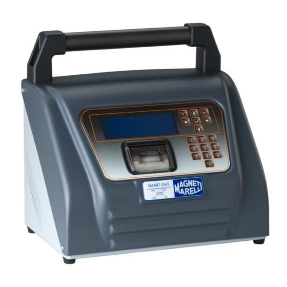
1 Package contents Gas analyzer Smart Gas/Logic 220V supply cable Serial cable for connection to the PC Exhaust gas sampling probe Logbook 1161306-0... -
Page 4: Warranty
2 Warranty 2.1 Warranty Coverage Magneti Marelli After Market Parts and Services (MM AM P&S) warrants the Product for 24 (Twenty four) Months starting from the date of the Product’s activation or the date of the original purchase turning out by the Purchase Documents. -
Page 5: Remedy
The Warranty excludes the repairing close the Customer. The Service Assistance Department doesn’t guarantee any Repairing Time, but is engaged to repair the Equipment as soon as possible. 2.3 Remedy To take advantage of the Warranty, the Customer has to send the Product in ‘Carriage Paid Shipment’... -
Page 6: Product Installation
In case of the Product sent for Repairing is not under Warranty, the Customer will be advised and will have to authorized the Repairing out-of-Warranty. The cost of the Repairing will be charged to the Customer. In case of unjustified demand of Warranty, the labor cost for checking and verifying the Product will be charged to the Customer. -
Page 7: Function Keys
3.2 Function keys Function key to gain access to the set-up Arrow keys to move menu, to activate the in the menus numeric writing mode, capital or small letters Alphanumeric keys to enter data 3.3 Gas probe connection The gas analysis probe features a metallic nozzle collecting the gases, and shall be inserted in the vehicle exhaust pipe, whereas the other side... -
Page 8: Probe Connection: Temperature And Rpm
Gas analyzer use Upon analyzer Smart Gas switch on the display will show a short introduction message, then the analyzer enters automatically in the main page where it is possible to select the type of test to be carried out. -
Page 9: Free Page
4.1 Free page Press the ENTER key (↵) on the main menu to enter in “Free page”. After turning on the instrument, the warm up phase begins (“WARM UP”); it is necessary to wait for the analysis cell to be properly warmed up before going on with the test. -
Page 10: Light Test And Gas Official Procedure
4.2 Light test and gas official procedure To carry out tests in "Official procedure" or for the "Light Test" it is necessary to use the rpm and temperature probes. If, for technical reasons, should it not be possible to use them, it is possible to manually enter all data in the analyzer. -
Page 11: Hc Test
4.2.3 HC test It checks the presence of hydrocarbons inside the gas sampling probe. Warning: do not insert the gas sampling probe in the vehicle exhaust pipe during this test. 4.2.4 Leak test It checks the analyzer pneumatic seal by creating a vacuum in the pneumatic circuit. -
Page 12: Print Report
4.2.6 Print report Repeat test Select the "Print" item and confirm it with the key ↵. Change result ►Print Enter the vehicle data: make, model, number plate, frame number, mileage, year of first registration. Lastly, enter the name of the technician that carries out the test. -
Page 13: Time And Date Set-Up
Time and Date confirm. ►Workshop data … ►Workshop name Select the workshop relevant items and press the key (↵) Address to confirm them. City … 4.3.2 Time and date set-up Upon initial message display at instrument switch-on, press the ESC or F function key;... -
Page 14: Use Of The Instrument Through Pc With Serial Connection
Use of the instrument through PC with serial connection The instrument is set to be connected to an external control system such as a Computer. The connection can be wireless (Bluetooth) or made with cables. As for the Bluetooth connection, the instrument must be equipped with a suitable internal Bluetooth module. -
Page 15: Pc Software Installation Procedure
6 PC software installation procedure Insert the CD contained in the package In case the CD is not automatically launched select the file setup.exe on the CD. Upon programme starting window shown in the figure will be displayed. Select the second item for the installation of the Greek version. -
Page 16: Software Use On Pc
Enter the software installation code supplied with the CD (it is written on the CD cover) Do not carry out any operation until the end of the installation 7 Software use on PC Select the programme icon present on the desktop or which accessed through the Windows start... -
Page 17: Using The Bluetooth Pairing Module
Select Diesel for the diesel free test Select Gas for the free test of petrol or gas vehicles. Select Official Test Diesel/Gas in order to carry out an official test according what required Standards in force. Upon test launching follow the displayed indications to carry test. - Page 18 Install the Bluetooth Pairing module present on the CD. installation programme will automatically launch the search for nearby devices. Select the required language. Once the search is ended, the window shown in the figure will be displayed. If one or more products have been found in the area they will be highlighted in black, otherwise the writings will stay grey.
-
Page 19: Instrument Cleaning
9 Instrument cleaning Warning: do not carry out any cleaning operation when the instrument is working. Proceed as follows to clean the instrument: Make sure that the multiple outlet switch is OFF. WARNING: Do not clean the inside part of the condensate separator chambers with alcohol. - Page 20 Clean the gas sam 1161306-0...
Need help?
Do you have a question about the Smart Gas and is the answer not in the manual?
Questions and answers