
Related Manuals for Motorline MC410


Summary of Contents for Motorline MC410
- Page 1 MC410 MC410 INSTALLER AND USER’S MANUAL R G B Y V+ LO ST PU OL LS LE LAMP ST PU CL LE v1.2 REV. 03/2021...
-
Page 2: Table Of Contents
00. CONTENT 01. SAFETY INSTRUCTIONS INDEX ATTENTION: 01. SAFETY INSTRUCTIONS This product is certified in accordance with European Community (EC) safety standards. 02. THE CONTROL BOARD TECHNICAL SPECIFICATIONS This product complies with Directive 2011/65/EU of the LEDs European Parliament and of the Council, of 8 June 2011, on CONNECTORS the restriction of the use of certain hazardous substances in electrical and electronic equipment and with Delegated... -
Page 3: Safety Instructions
01. SAFETY INSTRUCTIONS GENERAL WARNINGS the motorized door or gate from being triggered involuntarily. • This manual contains very important safety and usage information. WARNINGS FOR TECHNICIANS very important. Read all instructions carefully before beginning the installation/usage procedures and keep this manual in a safe place •... - Page 4 01. SAFETY INSTRUCTIONS RESPONSABILITY • Attach the permanent label for the manual release as close as possible to the release mechanism. • Supplier disclaims any liability if: • Disconnect means, such as a switch or circuit breaker on the electrical •...
-
Page 5: Technical Specifications 4A
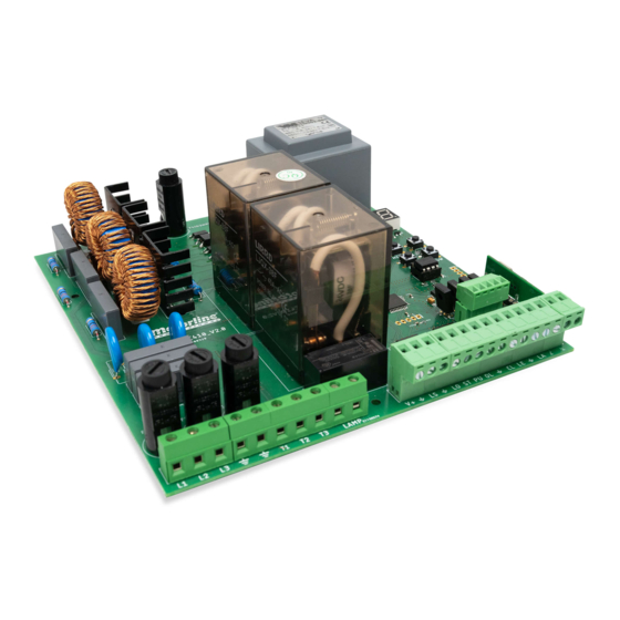
02. CONTROL BOARD TECHNICAL SPECIFICATIONS CONNECTORS The MC410 is a three-phase electronic control board (400V 3 phases) with a soft start and R G B Y V+ stop system, developed mainly to equip the engines STARK (sliding gates) and KVM115... -
Page 6: Installation
03. INSTALLATION INSTALLATION MAP (STARK) CLOSE OPEN Ground Ground... -
Page 7: Installation Map (Kvm105-Kvm110-Kvm115) 6A
03. INSTALLATION INSTALLATION MAP (KVM105-KVM110-KVM115) Green White Brown Grey Blue Orange Black White Ground Green (Green/Yellow) Ground (Green/Yellow) Brown Blue Black... -
Page 8: Programming
03. INSTALLATION 04. PROGRAMMING BASE INSTALLATION PROCESS PROGRAMMING AND DELETE TRANSMITTERS TRANSMITTER PROGRAMMING FOR TOTAL OPENING O processo de instalação, assume que o portão já tem as chapas de fim de curso instaladas. Para mais informações consulte o manual do motor. TRANSMITTER PROGRAMMING FOR PEDESTRIAN OPENING. -
Page 9: Functions
05. FUNCTIONS 05. FUNCTIONS MENUS P MENUS E MÁX. MIN. FACTORY FACTORY FACTORY MENU FUNCTION STATE MAX. MIN. FACTORY PROGRAMÁVEIS VALUE OL VALUE SE MENU FUNCTION STATE VALUE PROGRAMMABLE VALUE SE Prog. automatic Programação do curso Prog. semi automatic Deactivates present man Activates present man Slowing down at opening Activates present man - Close... -
Page 10: P0 | Automatic Programming 9A
05. FUNCTIONS 05. FUNCTIONS P0 | AUTOMATIC PROGRAMMING P0 | SEMI-AUTOMATIC PROGRAMMING This menu allows automatic programming of the engine and slowdown. This menu allows you to program the engine's working time in a semi-automatic way, allowing you to manually define the moment when the slowdowns start. Note •... - Page 11 05. FUNCTIONS 05. FUNCTIONS P1 - P2 - P3 - P4 P5 - P6 TIME ADJUSTMENT PHOTOCELLS 1 PROGRAMMING This menu allows you to define the slowdown time for each sheet when DEFAULT DEFAULT This menu allows you to program the LE safety behavior (photocell 1). opening and closing.
- Page 12 05. FUNCTIONS 05. FUNCTIONS P7- P8 - P9 E0 - E1 - E2 OPERATING LOGIC PRESENT MAN This menu allows to set the operating logic of the automation Enable or disable man present. Automatic Mode - Whenever there is an order, the movement is reversed. Present inactive man mode Step-by-step mode - Logic opens / stops / closes / stops.
- Page 13 05. FUNCTIONS 05. FUNCTIONS E3 - E5 - E6 - E7 E8 - E9 FOLLOW ME RESET – SELECT VERSION Disabled This menu allows you to reset the factory values for the two existing RESET RESET DEFAULT VALUE The control board, when in the open position, gives a closing order of 5 sec. after versions: (SECTIONAL) (SLIDING)
-
Page 14: Components Test
PEDESTRIAN OPENING BUTTON PRESSED NOTES: • This control board was developed only to work with Motorline motors, however if you CONTROL BOARD RUNNING OPENING COURSE want to work with motors from other manufacturers make sure that this motor is in star CONTROL BOARD RUNNING CLOSING COURSE configuration and that it is a 400V motor that does not exceed 1500W. -
Page 15: Troubleshooting
(see page 11B). technical services for diagnosis; technical services for diagnosis. problem, disconnect motors All control boards MOTORLINE have LEDs that A) SECURITY SYSTEMS: B) START SYSTEMS: easily allow to conclude which devices are 1 • Check if there is any with anomalies.
Need help?
Do you have a question about the MC410 and is the answer not in the manual?
Questions and answers