Advertisement
Advertisement
Table of Contents

Subscribe to Our Youtube Channel
Related Manuals for Motorline KVM 25


Summary of Contents for Motorline KVM 25
- Page 1 KVM 25 OPERATION MANUAL / INSTALLER v1.0 REV. 06/2014...
-
Page 2: Table Of Contents
CONTENTS SAFETY INSTRUCTIONS INDEX STANDARDS TO FOLLOW 00. CONTENTS ATTENTION: index | page 01.A To ensure the safety of people, it is important that you read all the following 01. SAFETY INSTRUCTIONS instructions.Incorrect installation or incorrect use of the product can cause physical standards to follow | page 01.B injury and material damage. -
Page 3: The Package
THE PACKAGE THE AUTOMATISM INSIDE THE PACKAGE LOCK / UNLOCK Inside the package you will find the following components: The automatism unlock function allows the user to open and close the gate manually, without having to remove the motor from the installation site. This funcionality is specially important in emergency cases and/or power cuts. -
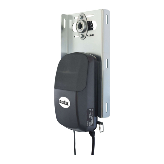
Page 4: The Automatism
THE AUTOMATISM INSTALLATION TECHNICAL SPECIFICATIONS PRE-INSTALLATION INFO KVM25 specifications For a proper installation and a durable performance of KVM25, be aware of the follow- are as follow: ing parameters: Please read all steps of this manual at least once, so that you know the full process KVM25 before starting the real assembling. -
Page 5: Installation
INSTALLATION INSTALLATION AUTOMATISM INSTALLATION AUTOMATISM INSTALLATION In the illustrated diagrams below and on the following page, are represented the ← 04 - Slightly loosen the bearing procedures for proper installation of the motor KVM25. bracket’s screws (left),to be able to move it sideways. - Page 6 INSTALLATION INSTALLATION AUTOMATISM INSTALLATION INSTALLATION MAP ↑ 07 - Place the automatism on the support plate (left), and assemble the chain on the motor’s pinion as you can see on the right image. Place the screws on the motor in order to support it on the metal plate, without tightening them completely, so that you are able to adjust the automatism.
-
Page 7: Programming
PROGRAMMING PROGRAMMING PROGRAMMING LIMIT SWITCHES PROGRAMMING LIMIT SWITCHES In the illustrated diagrams below and on the following page are represented the procedures for proper programming of the motor KVM25 limit switches, once installed on the gate. 01 - Unlock the motor, pulling the lever 02 - Open the automatism cover with a 05 - Move the close magnetic actuator 06 - Manually move the door to the... - Page 8 PROGRAMMING PROGRAMMING DESCRIPTION POTENTIOMETERS AJUSTMENT MOTOR INSTALLED ON LEFT SIDE: 6A This potentiometer adjusts the motor’s power when closing 6B This potentiometer adjusts the motor’s power when opening MOTOR INSTALLED ON RIGHT SIDE: 6A This potentiometer adjusts the motor’s power when opening 6B This potentiometer adjusts the motor’s power when closing Battery Input (A - Positive | B - Negative)
-
Page 9: Connection Scheme
CONNECTION SCHEME CONNECTING COMPONENTS TO CONTROL BOARD LED POWER LEARN LEARN CONNECTOR 2 ( INF ) - Works without photocells, not needing shunt. PUSH PUSH INFRD CONNECTOR 1 ( v+ ) - 15 VDC 1.5W máx. Battery Transf. Motor DV 12/24V 12/24V 08.A...
Need help?
Do you have a question about the KVM 25 and is the answer not in the manual?
Questions and answers