Table of Contents
Advertisement
Quick Links
Advertisement
Table of Contents

Related Manuals for Motorline TELICA


Summary of Contents for Motorline TELICA
- Page 1 TELICA USER’S AND INSTALLER’S MANUAL V2.1 REV. 02/2019...
-
Page 2: Table Of Contents
00. CONTENT 01. SAFETY INSTRUCTIONS INDEX STANDARDS TO FOLLOW ATTENTION: 01. SAFETY INSTRUCTIONS STANDARDS TO FOLLOW 02. THE PACKAGE This product is certified in accordance with European Community INSIDE THE PACKAGE (EC) safety standards. 03. OPERATOR DIMENSIONS TECHNICAL SPECIFICATIONS This product complies with Directive 2011/65/EU of the European Parliament and of the Council, of 8 June 2011, on the restriction 04. -
Page 3: Safety Instructions
01. SAFETY INSTRUCTIONS 01. SAFETY INSTRUCTIONS STANDARDS TO FOLLOW STANDARDS TO FOLLOW • It is important for your safety that these instructions are followed. properly. • Keep these instructions in a safe place for future reference. • If the automation is to be installed at a level higher than 2,5 m above ground •... -
Page 4: The Package
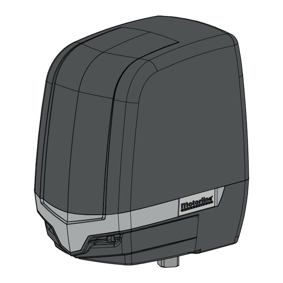
02. THE PACKAGE 03. OPERATOR INSIDE THE PACKAGE DIMENSIONS The dimensions of the TELICA automation are the following: Components on the 2 motor's package: Components on the 1 motor's package: 01 • 02 articulated motors 01 • 01 articulated motor 02a •... -
Page 5: Installation
QUOTA B • Horizontal distance between the center of the hinge and the center of the motor shaft. Fig. 5 stáculo. SUPPORTS INSTALLATION EXTERNAL UNLOCK The kit exemplified below is not included in the TELICA Kit. Security Fig. 9 1 • Drill holes for M8 screw anchors. CSV100 •... -
Page 6: Automatism Installation 5A
04. INSTALLATION 04. INSTALLATION AUTOMATISM INSTALLATION MICROS ADJUSTMENT Remove the automation's cover. To do this, loosen the two front screws, slightly tilt Fig. 15 the cover back and pull up. 1 • Place the motor on the support plate and Fig. -
Page 7: Troubleshooting
3 • Disconnect motor from control board and test it by connecting directly to power supply in order to find out if it has problems (see page 07A/07B) 4 • If the motor work, the problem is on the control board. Pull it out and send it to our MOTORLINE technical services for diagnosis;... -
Page 8: Components Test
To detect if the malfunction is on the control board or on the motor is, sometimes, necessary to perform To detect which are the components with problems in a 24Vdc TELICA automatism instalation, it's some- tests with connection directly to a 230Vac power supply. -
Page 9: Connection Scheme
07. CONNECTION SCHEME 230V/110V MOTOR (MC2) Antenna * For more informations, check the manual Pedestrian of the photocells Opening to be installed. (1 leaf) Exterior Interior Photocells* Photocells* Close the circuit with bridge (shunt) Complete when the Opening photocells circuit (2 leaves) is not being used! Lock... - Page 10 07. CONNECTION SCHEME 24V MOTOR (MC11)
Need help?
Do you have a question about the TELICA and is the answer not in the manual?
Questions and answers