Advertisement
Advertisement
Table of Contents

Related Manuals for Motorline SP WING 400


Summary of Contents for Motorline SP WING 400
- Page 1 SP WING 400 Operating and installation instructions 1 ...
- Page 2 General safety instructions and checklist This electric gate operator complies with European Directives: 89/336/EEC and 73/23/EEC and subsequent amendments. When installed correctly this electrically operated motor complies with all relevant safety standards. Please ensure the operating manual is fully read and understood before installation and operation. Installation should only be carried out by a competent and qualified person.
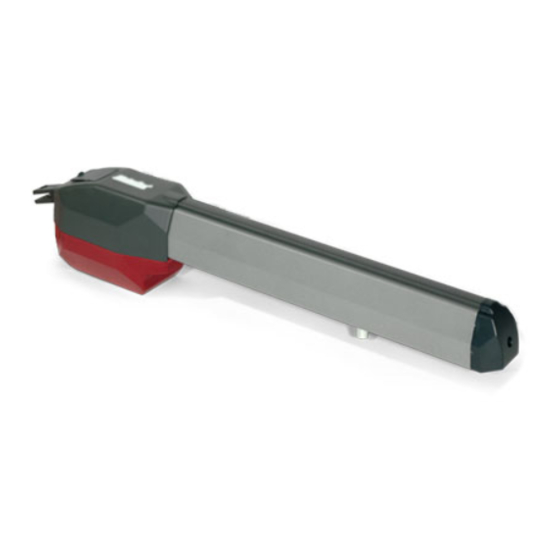
- Page 3 Monthly 1. Description The SP Wing 400 is an electro-mechanical gate operator which drives the gate by worm screw drive. The motor has integral opening and closing limit switches. The operator is irreversible and locks mechanically in the open and closed position when not in use.
-
Page 4: Technical Specification
2. Technical Specification 4 ... -
Page 5: Preliminary Checks
3. Packaging 4. Pre-liminary checks Ensure the gate leaf is securely installed, and has no signs of wear. The gate must be fixed on suitable hinges to enable easy and free opening and closing. Gate leaf must be within size and weight restraints to suit the motor capability – maximum 2.5 metres in width. -
Page 6: Installation Dimensions
5. Installation Dimensions 95° 120° Determine the position of the gate motors on the gate leaf and gate post, taking care to avoid any obstacles such as walls, fences or plants etc Please ensure the opening and closing angles of the gate do not create any possible crushing zones between gate and post. - Page 7 2 - Mount the Ram motor onto the rear bracket and secure in place with the bolt provided. 3 – Ensure the front fixing on the motor is in position, for mounting to top bracket of gate leaf. If not the motor can be released to manual and moved by hand, or temporarily power up the motor to move the position.
- Page 8 5 – Close the gate leaf and whilst keeping motor horizontal, secure the front bracket to the gate leaf. 6 – Ensure the motor is manually released. Push the gate leaf open and closed and check the movement is smooth with no significant friction points. 7.
-
Page 9: Limit Switches
After wiring has been checked, replace base cover and fix in place with fixings as shown below. 8. Limit Switches The SP Wing 400 is supplied with on board limit switches. To set up the open and closed limits unscrew the front end cap of the motor, as shown in Fig 22. -
Page 10: Maintenance Schedule
9. Commissioning Once the system has been fully fitted and connected to control panel (MC2), the system needs to be fully commissioned and tested. It is recommended to have the swing gates locked in the half open / closed on the first operation, just to ensure that the motor is running the right direction on the first command.
Need help?
Do you have a question about the SP WING 400 and is the answer not in the manual?
Questions and answers