
Subscribe to Our Youtube Channel
Related Manuals for Motorline 800A


Summary of Contents for Motorline 800A
- Page 1 English AUTOMATION SYSTEMS FOR SLIDING GATES Operating and installation instructions SLIDE SERIES v1.0 Rev 11/2012...
-
Page 2: Table Of Contents
INDEX 1) General Safety Regulations ........................pág. 01 2) Description ..............................pág. 02 3) Technical Speci cations ......................... pág. 03 4) System Description ..........................pág. 03 5) Accessories ..............................pág. 04 6) Installation Tools ............................pág. 04 7) Installation ..............................pág. 05 8) Maintenance ............................... -
Page 3: General Safety Regulations
1) GENERAL SAFETY REGULATIONS 1) ATTENTION! To ensure the safety of people, it is important that you read all the following instructions. Incorrect installation or incorrect use of the product could cause serious harm to people. 2) Carefully read the instructions before beginning to install the product. 3) Do not leave packing materials (plastic, polystyrene, etc.) within reach of children as such materials are potential sources of danger. -
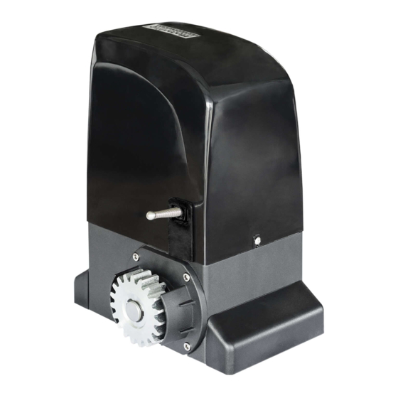
Page 4: Description
2) DESCRIPTION Automated system for residential or industrial sliding gates with a maximum of 2000kgs. It consists of a reversing electro-mechanical gearmotor, powered by a 230V control unit. The automated system houses a programmable electronic control board that enables setting of function logics, work time and pause time, anti-crushing sensitivity as well as partial-opening width. -
Page 5: Technical Speci Cations
3) TECHNICAL SPECIFICATIONS Technical speci cations of the automated operator: Model 800A OL1500 OL2000 Power supply (V) 230V , 50Hz 230V , 50Hz 230V , 50Hz Rated absorbed power (W) 370W 550W 1000W Max speed (m/sec) 12m/min 12m/min 12m/min Working time... -
Page 6: Accessories
Note: 1) To lay down electric cables, use rigid and/or exible adequate tubes. 2) To avoid any kind of interference, always separate low voltage connection cables from AC230V power cables. 3) The description of system is standard system, but we did not provide all parts. If you want system accessories, please contact us. -
Page 7: Installation
7) INSTALATION 7.1. Preliminary checks To ensure safety and an e ciently operating automated system, make sure the following conditions are applied: - The structure of the gate must be suitable for being automated. In particular, check that the structure is su ciently strong and rigid, and that its dimensions and weight conform to those indicated in the technical speci cations;... - Page 8 b) Put the foundation plate to the oor, using adequate expansion plugs and provide one or more tubes for routing the electric cables through the plate (Fig10 and 11). Using a level, check if the plate is perfectly horizontal. Fig. 10 Fig.
- Page 9 7.5. Adjusting the operator Adjust the distance of the operator from the gate by referring to Fig.13. 57 mm Fig. 13 7.6. Fixing operator Fix the operator slightly tightening the screws as shown in Fig. 14. IMPORTANT: After the installation, you must remove the exhaust screw (Applicable in OL1500 and 2000) Fig.
-
Page 10: 7.7. Releasing The Operator
After the upper-cover xed, please install the side-cover (Fig. 17). Fig. 17 7.7. Releasing the operator Prepare the operator for manual operating mode as described below: Insert supplied key on the lock, turn it clockwise 90° (Fig.18), pull and open the manual release (Fig.19). Fig. - Page 11 c) Move the gate to manually back and forth, to ensure that the gear rack is properly seated on the pinion and movement occurs smoothly. d) Set the rack in the gate. (Fig. 21) .To ensure a correct xation, can go slowly moving the gate and setting the gate spacers always near the pinion.
-
Page 12: Maintenance
7.9. Installing limit switch plate a) After having rack nstalled, take the gate back to the closed position and position the limit swicth plate on the rack. In this closed position, the plate should trigger the limit switch of the motor. b) Tighten the screws DIN912 M5x12 included in the pack, until it touches the rack, squeezing it.
Need help?
Do you have a question about the 800A and is the answer not in the manual?
Questions and answers