Table of Contents
Advertisement
Quick Links
Instructions - Parts List
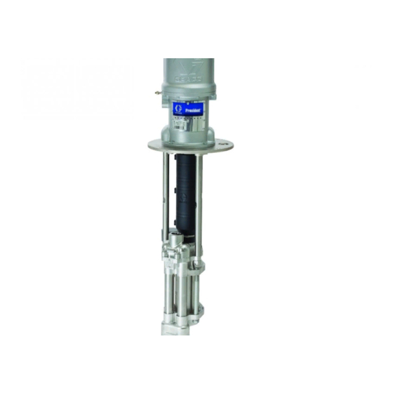
President
Pumps
Air-powered pumps for low pressure, high volume circulation of finishing materials.
Do not use for flushing or purging lines with caustics, acids, abrasive line strippers, and
other similar fluids. For professional use only.
Important Safety Instructions
Read all warnings and instructions in this
manual. Save these instructions.
See page 2 for model information, including
maximum working pressure.
US Patent Pending
®
4-Ball
3A1450B
ENG
TI16614a
II 2 G
c IIB T3
Advertisement
Table of Contents

Subscribe to Our Youtube Channel
Related Manuals for Graco President 24H627


Summary of Contents for Graco President 24H627
- Page 1 Instructions - Parts List ® President 4-Ball Pumps 3A1450B Air-powered pumps for low pressure, high volume circulation of finishing materials. Do not use for flushing or purging lines with caustics, acids, abrasive line strippers, and other similar fluids. For professional use only. Important Safety Instructions Read all warnings and instructions in this manual.
-
Page 2: Table Of Contents
Graco Standard Warranty ....20 Graco Information ......20... -
Page 3: Warnings
Warnings Warnings The following warnings are for the setup, use, grounding, maintenance, and repair of this equipment. The exclama- tion point symbol alerts you to a general warning and the hazard symbols refer to procedure-specific risks. When these symbols appear in the body of this manual, refer back to these Warnings. Product-specific hazard symbols and warnings not covered in this section may appear throughout the body of this manual where applicable. - Page 4 Warnings WARNING WARNING WARNING WARNING PERSONAL PROTECTIVE EQUIPMENT You must wear appropriate protective equipment when operating, servicing, or when in the operating area of the equipment to help protect you from serious injury, including eye injury, hearing loss, inhalation of toxic fumes, and burns.
-
Page 5: Installation
Installation Installation Grounding Object being sprayed: follow local code. Solvent pails used when flushing: follow local code. Use only conductive metal pails, placed on a grounded surface. Do not place the pail on a nonconductive sur- face, such as paper or cardboard, which interrupts The equipment must be grounded. -
Page 6: Plumbing
Installation Plumbing • Pump air regulator (L): to control pump speed and outlet pressure. Locate close to the pump. See F . 2. Install a fluid shutoff valve (D) between the • Air line filter (K): removes harmful dirt and mois- mix tank (A) and the pump. - Page 7 Installation TI16616a . 2. Typical Installation Key: Mix Tank Air Shutoff Valve (bleed-type) 255143 Wall Bracket Accessory (253692 Pump Stand Air Supply Line Accessory is also available) Air Line Filter Fluid Supply Line; 1-1/2 in. (38 mm) minimum diameter Air Regulator and Gauge Fluid Shutoff Valve Bleed-Type Master Air Valve Fluid Line...
-
Page 8: Operation
Operation Operation Pressure Relief Procedure 9. Verify that pump actuations are priming the pump wet-cup. If not, confirm that the TSL pump piston is being depressed at bottom changeover, and that reservoir check valves are not stuck closed. 10. Close the fluid shutoff valve (D) downstream of the 1. -
Page 9: Maintenance
Maintenance Maintenance Preventive Maintenance Stall Test Schedule Perform a stall test periodically to ensure the piston seal is in good working condition and prevent system over- The operating conditions of your particular system pressurization: determine how often maintenance is required. Establish a preventive maintenance schedule by recording when Close the fluid shutoff valve (D) closest to the pump on and what kind of maintenance is needed, and then... -
Page 10: Changing The Tsl
Maintenance Changing the TSL To change the TSL: 1. Shut off the pump. Check the condition of the TSL and the level in the res- ervoir every week, minimum. TSL should be changed at least every month. Part No. 206995 Throat Seal Liquid (TSL) carries resi- due from the pump rod into the reservoir. -
Page 11: Troubleshooting
Troubleshooting Troubleshooting Problem Cause Solution Pump output low on both strokes. Restricted air supply lines. Clear any obstructions; be sure all shutoff valves are open; increase pressure, but do not exceed maximum working pres- sure. Exhausted fluid supply. Refill and reprime pump. Clogged fluid outlet line, valves, etc. -
Page 12: Repair
Repair Repair Disassembly Reassembly NOTE: If the coupling adapter (108) and tie rods (104) have been disassembled from the motor, see Reassem- ble the Coupling Adapter and Tie Rods to the Motor on page 13. 1. Relieve the pressure, see Pressure Relief Proce- dure page 8. -
Page 13: Reassemble The Coupling Adapter And Tie Rods To The Motor
Repair Reassemble the Coupling Adapter and Tie Rods to the Motor NOTE: Use this procedure only if the coupling adapter (108) and tie rods (104) have been disassembled from the motor, to ensure proper alignment of the motor shaft to the piston rod (R). 1. - Page 14 Repair 3A1450B...
-
Page 15: Parts
Parts Parts 24H627 3:1 Ratio Pump with 750cc CST Lower 24H628 3:1 Ratio Pump with 750cc SST Lower 24H629 2:1 Ratio Pump with 1000cc SST Lower 24H997 2:1 Ratio Pump with 1000cc CST Lower 24J074 3:1 Ratio Pump (stubby size) with 750cc CST Lower 24J075 3:1 Ratio Pump (stubby size) with 750cc SST Lower Ref. -
Page 16: Dimensions
Dimensions Dimensions TI16614a Approx. Weight Model Lower Size in. (mm) in. (mm) in. (mm) in. (mm) lb (kg) 24H627 750cc 73 (33) 24H628 750cc 46.3 (1176) 29.8 (757) 24H629 1000cc 17.5 (445) 11.5 (292) 74 (34) 24H997 1000cc 24J074 750cc 40.4 (1026) 24.0 (610) 71 (32) -
Page 17: Mounting Hole Layouts
Mounting Hole Layouts Mounting Hole Layouts 255143 Wall Bracket Accessory 17.75 in. (451 mm) 2.0 in. (51 mm) 5.375 in. (137 mm) 7.375 in. 11.75 in. (187 mm) (299 mm) 5.25 in. (133 mm) Four 9/16 in. (14 mm) 1.0 in. diameter holes for (25 mm) mounting to stand... -
Page 18: Performance Charts
Performance Charts Performance Charts Fluid Outlet Pressure Air Consumption To find fluid outlet pressure (MPa/bar/psi) at a specific flow To find air consumption (l/min. or gpm) at a specific fluid flow (lpm/gpm) and operating pressure (A/B/C): (l/min. or gpm) and operating pressure (A/B/C): Locate desired flow at bottom of chart. -
Page 19: Technical Data
Technical Data Technical Data Maximum Fluid Maximum Fluid Maximum Fluid Flow at 60 Temperature Working Pressure Air Input Pressure cycles per minute Output per Cycle Rating Model psi (MPa, bar) psi (MPa, bar) Air Consumption gpm (lpm) gal. (cc) °F (°C) 24H627 460 (3.2, 32.0) 150 (1.0, 10) -
Page 20: Graco Standard Warranty
With the exception of any special, extended, or limited warranty published by Graco, Graco will, for a period of twelve months from the date of sale, repair or replace any part of the equipment determined by Graco to be defective.
Need help?
Do you have a question about the President 24H627 and is the answer not in the manual?
Questions and answers