Advertisement
293 Wright Street, Delavan, WI 53115
© 2000, Sta-Rite Industries, Inc. PRINTED IN U.S.A.
PumpBiz.com
1-800-PUMPBIZ
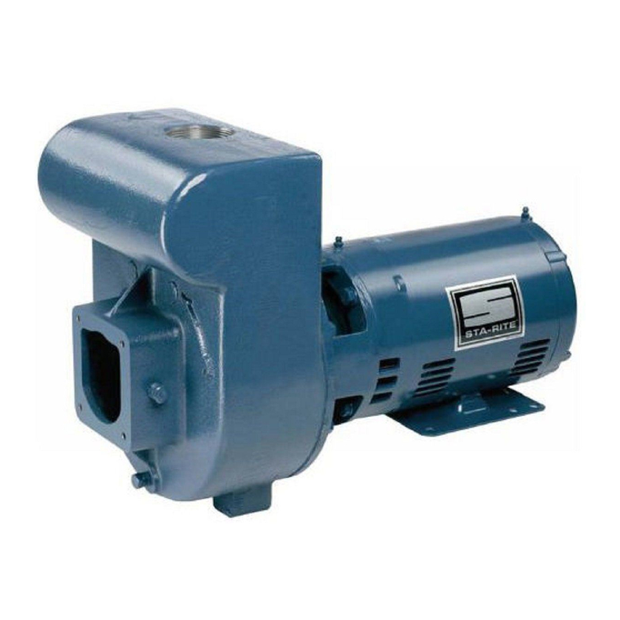
"D" Series
Installation/Operation/Parts
For further operating, installation,
or maintenance assistance:
Call 1-262-728-5551
OWNER'S MANUAL
Self-Priming
Centrifugal Pumps
1362 1094ASBN
S976 (Rev. 10/3/00)
Advertisement


Need help?
Do you have a question about the D Series and is the answer not in the manual?
Questions and answers