
Related Manuals for enervent LTR-3 Series


Summary of Contents for enervent LTR-3 Series
- Page 1 LTR-3 PLANNING, INSTALLATION AND OPERATION INSTRUCTIONS Kipinätie 1, 06150 BORGÅ FINLAND Phone +358 207 528 800, fax +358 207 528 844 www.enervent.fi 2006_1...
-
Page 2: Model
MODEL Before you begin reading, confirm the model of your appliance. These instructions cover the following models: LTR-3- 85 LTR-3-120 LTR-3-85 E LTR-3-120 E LTR-3-85 EP LTR-3-120 EP ____________________________________________________________ EXPLANATION OF THE MARKS AND NUMBERS LTR-3-85 Fan efficiency 130 W LTR-3-120 Fan efficiency 185 W Electrical heating coil 500 W (built-in), with thermostat. -
Page 3: Introduction
GUARANTEE Enervent Oy Ab admits a two (2) year product guarantee on the LTR-3 range. The guarantee covers the repair work with the necessary spare parts. Repair service will be carried out at the factory premises in Porvoo, Finland or as agreed. -
Page 4: Table Of Contents
TABLE OF CONTENTS MODEL page INTRODUCTION GUARANTEE TABLE OF CONTENTS WARNING OPERATING PRINCIPLE INSTALLATION PARTS PLANNING OF THE DUCT SYSTEM EXHAUST AIR CLASSIFICATION OF LIVING AREAS PHASES OF INSTALLATION INSTRUCTIONS FOR THE DUCT HEATER INSTALLATION OF THE DUCT HEATER MAINTENANCE OF THE DUCT HEATER HEAT INSULATION OF AIR DUCTS OPERATION MAINTENANCE... -
Page 5: Operating Principle
OPERATING PRINCIPLE The LTR-3 ventilation unit is based on regenerative heat recovery. This is achieved with a rotating heat exchanger through the halves of which incoming air and exhaust air flow in opposite directions. Aluminium foils of the heat exchanger transfer heat from the exhaust air to the supply air. - Page 6 ADDITIONAL EQUIPMENT - Plain filter EU5 - Bag filter EU5 or EU7 Pulser Triac regulator Bag filter EU7 Filter EU7 + duct casing Electrical heater for installation in duct Plain filters EU5...
-
Page 7: Planning Of The Duct System
PLANNING OF THE DUCT SYSTEM It is recommended that the task of dimensioning the duct system is given to a professional engineer. The ducts must be large enough, min. Ø 100 mm, to allow a sufficiently low air speed. In particular the outside feed and the waste air ducts need to be wide. - Page 8 The distances between waste air and fresh air openings. Usually fresh air is taken from a north facing wall and the waste air is led out from the roof. Other methods are acceptable, so long as they fall within the guidelines laid out by the Ministry of the Environment’s code of building regulations (D2: Finland 2003, extract shown below), or in accordance with your local directives and regulations governing indoor climate and building ventilation.
-
Page 9: Exhaust Air Classification Of Living Areas
EXHAUST AIR CLASSIFICATION OF LIVING AREAS The leading of waste air from a building is based on the following, exhaust air classification Class 1 Exhaust air which contains few impurities. The impurities are mainly from people or structures. Air is suitable for return air and transfer air. Class 2 Exhaust air which contains some impurities. -
Page 10: Phases Of Installation
INSTALLATION PHASES The unit can be installed in a warm, half warm or cold room. If the unit is installed in a cold room, is it to be equipped with a 100 mm thick cover of isolation. The unit can be installed i.e. -
Page 11: Instructions For The Duct Heater
INSTRUCTIONS FOR THE DUCT HEATER Instructions for installing the duct heaters E09KP-016 and E18KP-016 in circular ducts. NB! Read these instructions before installing and connecting the duct heaters. 1. The duct heaters are designed to operate on single phase alternating current. See the wiring diagram for the particular heater and the electrical data on the rating plate placed on the cover of the duct heater. -
Page 12: Installation Of The Duct Heater
INSTALLATION OF THE DUCT HEATER 1. The heater is designed for insertion into standard spiral ducting and is fixed to the ducting with screws. 2. The air must flow through the heater in the direction of the arrow (located on the side of the heater close to the connection box). -
Page 13: Maintenance Of The Duct Heater
MAINTENANCE OF THE DUCT HEATER No maintenance is required except a periodic functional test. Overheating When the overheating cut-out with manual reset has been activated, the following should be observed: 1. The heater must not be interfered with in any way, such as removal of the cover, except by an authorized electrical fitter. -
Page 14: Heat Insulation Of Air Ducts
HEAT INSULATION OF THE DUCTING SYSTEM Insulator 20mm Closed cell type Insulation 2 x 100mm The figure shows different examples of ductwork insulation. 1. Exhaust air duct in warm state (indoor, no insulation). 2. Waste air duct and fresh air duct in warm state (indoor). Insulation, for example Armaflex™... -
Page 15: Operation
OPERATION The ventilation unit must run continuously and the desired effect is regulated from the control panel. It is possible to switch off the heat recovery for example during the summer when the outside and inside temperatures are the same, or when one wants to cool the indoor air with cool night air. -
Page 16: Maintenance
MAINTENANCE LTR-3 does not require any mechanical maintenance, only changing of the filters periodically and cleaning of the heat exchanger and fans (when needed). The power supply to the unit is cut when the service hatch is opened. Wait for two (2) minutes before starting the maintenance work! Although the units power supply is cut when the hatch is opened, the fans still rotate and the electrical coil in E-/EP-models is still hot for a while. - Page 17 B. Disconnect the heat exchanger plug. Pull the heat exchanger from the appliance.; Remove the cover plate by unfastening the 6 screws. Picture 1 C. Lie the heat exchanger on its side. Remove the gasket from the space beam. Unfasten the centre socket-head screw;...
-
Page 18: Air Flow Reference Values
TARGET VALUES FOR AIR FLOWS Target values for air flows in the living areas. EXHAUST AIR Kitchen Bathroom 15 –17 Toilet 10 –12 Clothing room 3 –4 Hobby room l/s, m² Dressing room l/s, m² Washroom 15 –17 Cleaning cupboard l/s, m²... -
Page 19: To Be Observed During Operation
TO BE OBSERVED DURING OPERATION! Always ventilate with a high enough efficiency! Otherwise the indoor humidity will rise too high and condensation will form on for instance cold window surfaces. The recommended relative humidity for indoor air is 40 …45 % (room temperature 20...22 °C). -
Page 20: Characteristics
CHARASTERISTICS... -
Page 22: Electrical Wiring Diagrams
WIRING DIAGRAMS... -
Page 26: System Planning Example
PLANNING EXAMPLE... -
Page 27: Fault / Correction Guide
FAILURE SEARCH and TROUBLE SHOOTING SUPPLY AIR TOO COLD Reason Action * The rotor switch is in position 0 Switch to position 1 * Belt of the heat exchanger broken Replace the belt * Belt greasy, causing slippage Contact a service man * The exhaust fan has stopped Contact a service man * The exhaust air filter is blocked... -
Page 28: Declaration Of Conformity
Description of the product: Ventilation unit with heat recovery Trade name of the product: Enervent LTR-3-85, LTR-3-85E, LTR-3-85EP, LTR-3- 85E09KP, LTR-3-85E18KP Enervent LTR-3-120, LTR-3-120E, LTR-3-120EP, LTR-3- 120 E09KP, LTR-3-120E18KP Representatives for the products in the region of ETA: Ventilair AB, Ulvsjö, 79699 ÄLVDALEN, SVERIGE... -
Page 29: Technical Data
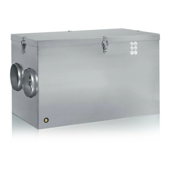
TECHNICAL DATA Dimensions Height 500 mm Width 833+50 mm Depth 470 mm Current 230 V / 50 Hz 1 phase Fuse 10 A, fast Fans Exhaust air Model Rating 185 W max. Current 0,57 0,80 A Heat protection Supply air Model Rating 185 W max.
Need help?
Do you have a question about the LTR-3 Series and is the answer not in the manual?
Questions and answers