Valor L1 Series Installation Instructions Manual
Linear 3-1/2” surround kit
Hide thumbs
Also See for L1 Series:
- Installation & owner's manual (68 pages) ,
- Installation and upgrades (12 pages) ,
- Installation instructions manual (9 pages)
Table of Contents
Advertisement
Available languages
Available languages
Quick Links
INSTALLATION INSTRUCTIONS
Linear 3-1/2" Surround Kit 1550LSBV2
Approved for use with Valor models 1500 and 1600 ONLY
DANGER
!
A barrier designed to reduce the risk of burns from the hot
viewing glass is provided with this appliance and must be
installed for the protection of children and other at-risk
individuals.
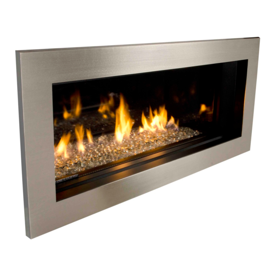
Trim size
The 1550v2 Linear 3-1/2" Surround Kit is designed to be
used on the Linear L1 1500 and Linear L1 2-sided 1600
Valor heaters.
The application of this kit does not affect the venting
capabilities or method of preparation of the heater as
described in the heater installation manual.
This trim fits flat against the cement board with the ability
to tuck additional non-combustible materials up to 1/2"
thickness behind the trim.
Replacing the side panels on the trim allow non-
combustible material thickness to be increased to 1".
4005356-03
© Copyright Miles Industries Ltd., 2020.
L1 Series
HOT GLASS WILL
CAUSE BURNS.
DO NOT TOUCH GLASS
UNTIL COOLED.
NEVER ALLOW CHILDREN
TO TOUCH GLASS.
46-3/16" (1173 mm)
Thickness 1-3/8" (35 mm)
INSTALLER: Leave this
manual with the appliance.
CONSUMER: Retain this
manual for future reference.
Note: This kit must be
installed or serviced by a
qualified installer, service
agency or gas supplier. These
instructions are to be used
in conjunction with the main
installation instructions
for the above listed heater
model.
LH Trim panel
LH Side door
Barrier screen
Overview (Fireplace engines sold separately)
Non-
combustible
cement board
Plinth
RH Side
Trim
door
RH Trim panel
1
Advertisement
Table of Contents

Related Manuals for Valor L1 Series


Summary of Contents for Valor L1 Series
- Page 1 INSTALLATION INSTRUCTIONS L1 Series Linear 3-1/2” Surround Kit 1550LSBV2 Approved for use with Valor models 1500 and 1600 ONLY DANGER INSTALLER: Leave this manual with the appliance. CONSUMER: Retain this HOT GLASS WILL manual for future reference. CAUSE BURNS. DO NOT TOUCH GLASS Note: This kit must be UNTIL COOLED.
-
Page 2: Installation
Considerations—Finish Wall Thickness Installation This trim can be adjusted according to the thickness 1. Locate trim inside perimeter of ‘window’ aperture of the non-combustible wall finish. Two options of flanges, press firmly against finished face of wall. installation can be used: •... - Page 3 3. Position plinth in space between glass and trim, 4. Identify left hand door and its orientation according locate ends onto end support. Ensure plinth is level to the images below. with trim. Left door Notes : - The opening in the plinth should be oriented as TOP of door: this space is shown below to allow air to enter while obstructing...
-
Page 4: Removing The Screen
Installation of the barrier screen Removing the screen 1. Hold the screen on the sides and locate the top into The barrier screen will need to be removed to access the the channel inside the top section of the surround. fireplace controls or for maintenance. -
Page 5: Repair Parts List
Because our policy is one of constant development and improvement, details may vary slightly from those given in this publication. Designed and Manufactured by / for Miles Industries Ltd. 190 – 2255 Dollarton Highway, North Vancouver, B.C., CANADA V7H 3B1 Tel. 604-984-3496 Fax 604-984-0246 www.valorfi replaces.com... -
Page 6: Guide D'installation
Épaisseur 1-3/8” (35 mm) La Bordure Linear 3-1/2” 1550v2 est conçue pour installer sur Pare-étincelles Plinthe les foyers Valor Linear L1 1500 et L1 à 2 côtés 1600. Porte L’installation de ce kit n’affecte pas l’évacuation ou méthode Bordure droite Panneau droit de préparation du foyer 1500 tel que décrit dans le guide... - Page 7 Considérations—épaisseur de la finition 2. Placez les panneaux d’extension sur la bordure tel qu’indiqué et fixez-les avec les 6 écrous (3 de du mur chaque côté). Cette bordure est ajustable selon l’épaisseur du mur incombustible fini. Deux options d’installation sont offertes : •...
- Page 8 3. Placez la plinthe dans l’espace entre la fenêtre et la 4. Identifiez la porte gauche et son orientation selon bordure. La plinthe repose sur le rebord au bas de les images ci-dessous. la bordure; assurez-vous que le bord de la plinthe Porte gauche est égal au bord de la bordure.
-
Page 9: Entretien
Installation du pare-étincelles Enlèvement du pare-étincelles 1. En le tenant par les côtés, insérez le haut du pare- Le pare-étincelles doit être enlevé pour avoir accès aux étincelles dans la rainure de la bordure. commandes du foyer ou pour l’entretien. Pour enlever le pare-étincelles, soulevez-le à... -
Page 10: Liste De Pièces
Liste de pièces Description Numéros de pièces Porte gauche 4002957AZ Porte droite 4002959AZ Panneau d’extension gauche 4003090AZ Panneau d’extension droit 4003091AZ Plinthe 4002929AZ Bordure 4005362 Pare-étincelles 4004215 Vis noires n 8 x 3/8 (4) 100A757 Parce que nous favorisons une politique de développement continu, certains détails de la présente publication peuvent varier. Conçue et fabriquée par / pour Miles Industries Ltd.
Need help?
Do you have a question about the L1 Series and is the answer not in the manual?
Questions and answers