Table of Contents
Advertisement
Quick Links
Advertisement
Table of Contents

Subscribe to Our Youtube Channel
Related Manuals for Spectra PowerBox 210 Series


Summary of Contents for Spectra PowerBox 210 Series
- Page 1 Spectra PowerBox 210-Series USER MANUAL Version 1.15 – February 2021 ...
-
Page 2: Table Of Contents
3.1 Removing the Top Cover ……...……………………………….….…………………..29 3.2 Installing SO-DIMM Memory………………………..…………..…………….……………31 3.3 Installing Mini-PCIe Cards on Bottom Side……..……………………………..32 3.4 Installing a SATA Hard Drive…………………………………………………………………34 3.5 Installing a Half-Slim SSD….…………………………………………………………………35 Spectra GmbH & Co. KG User Manual sales@spectra.de Spectra PowerBox 210 ... - Page 3 Chapter 5 Product Application (For DIO Only) 5.1 Digital I/O (DIO) application ………..………………………………………………………62 5.1.1 Digital I/O Programming Guide ……………………………………………………62 5.2 Digital I/O (DIO) Hardware Specification ……………………………………………………73 5.2.1 DIO Connector Definition ………………..……...…………….........74 Spectra GmbH & Co. KG User Manual sales@spectra.de Spectra PowerBox 210 ...
- Page 4 6.12 Installing a PB-210-PoE Module…….…..…………..……………………..……….……..96 6.13 Installing a PB-210-MEC-LAN Module…….…….………..………………..……………..98 6.14 Installing a PB-210-MEC-COM Module………….…..……………………..……………103 6.15 Installing a Side Mount Bracket.….…..……………………………………..……….……107 6.16 Installing a VESA Mount Bracket .…..……………………………………..……….……..109 Spectra GmbH & Co. KG User Manual sales@spectra.de Spectra PowerBox 210 ...
-
Page 5: Revision
Add Half Slim SSD/ MEC-LAN/ MEC-COM Installation 2021/01/25 Copyright Notice © 2021 by Spectra GmbH & Co. KG. All rights are reserved. No parts of this manual may be copied, modified, or reproduced in any form or by any means for commercial use without the prior written permission of Spectra GmbH &... -
Page 6: Product Warranty Statement
Product Warranty Statement Warranty Spectra products are warranted by Spectra GmbH & Co. KG to be free from defect in materials and workmanship starting from the date of purchase by the original purchaser. The actual warranty period of Spectra products vary with product categories. During the warranty period, we shall, at our option, either repair or replace any product that proves to be defective under normal operation. -
Page 7: Technical Support And Assistance
(manuals, cable, etc.) and any components from the system. If the components were suspected as part of the problems, please note clearly which components are included. Otherwise, Spectra is not responsible for the devices/parts. Repaired items will be shipped along with a "Repair Report" detailing the findings and actions taken. -
Page 8: Conventions Used In This Manual
11. If the equipment is not used for a long time, disconnect it from the power source to avoid damage by transient overvoltage. 12. Never pour any liquid into an opening. This may cause fire or electrical shock. Spectra GmbH & Co. KG User Manual sales@spectra.de Spectra PowerBox 210 ... - Page 9 14. CAUTION: Danger of explosion if battery is incorrectly replaced. Replace only with the same or equivalent type recommended by the manufacturer. 15. Equipment intended only for use in a RESTRICTED ACCESS AREA. Spectra GmbH & Co. KG User Manual sales@spectra.de Spectra PowerBox 210 ...
-
Page 10: Package Contents
Note: Notify your sales representative if any of the above items are missing or damaged. Ordering Information Model No. Product Description Intel® Pentium® Processor N4200 Compact Size Fanless Spectra PowerBox 210-N42 Computer Spectra GmbH & Co. KG User Manual sales@spectra.de Spectra PowerBox 210 ... -
Page 11: Chapter 1 Product Introductions
Chapter 1 Product Introductions Spectra GmbH & Co. KG User Manual sales@spectra.de Spectra PowerBox 210 ... -
Page 12: Overview
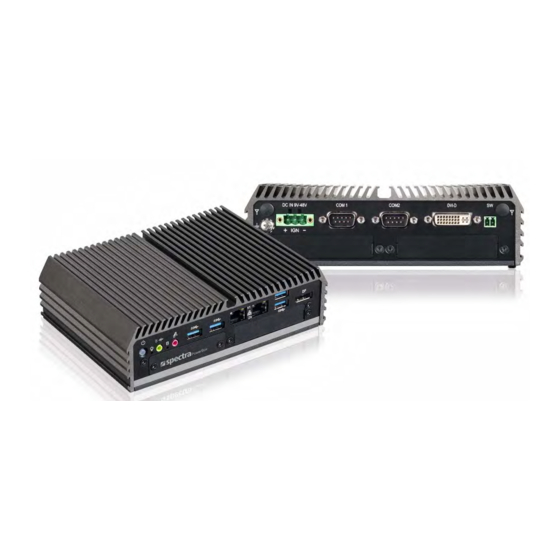
1.1 Overview Based on Intel® Pentium® N4200 quad-core processor, the Spectra PowerBox 210 is a fanless embedded computer offering an incredible size-performance ratio for the most challenging environments. Despite its compact size, the Spectra PowerBox 210 incorporates extensive connectivities including serial ports, USB 3.0, GbE LAN, full-size Mini-PCIe slot, dual SIM sockets, DVI-D, and DisplayPort. -
Page 13: Product Pictures
2 x Full Size Mini-PCIe Socket, 2 x SIM Card Socket Compact Size (185 x 131 x 56.5 mm) Wide Operating Temperature -40°C to 70°C E-mark (E13, No. 10R-0515075), LVD EN60950-1 Spectra GmbH & Co. KG User Manual sales@spectra.de Spectra PowerBox 210 ... -
Page 14: Hardware Specification
• In-Vehicle: E-Mark (E13, No. 10R-0515075) Other Function • Watchdog Timer: Software Programmable Supports 256 Levels System Reset • SuperCap Integrated for CMOS Battery Maintenance-free Operation • Supports Instant Reboot Technology (0.2 sec) Spectra GmbH & Co. KG User Manual sales@spectra.de Spectra PowerBox 210 ... -
Page 15: System I/O
Used to connect the system to a local area Used to set up IGN function network Clear CMOS Used to clear CMOS to reset BIOS 1.6.2 Rear Spectra GmbH & Co. KG User Manual sales@spectra.de Spectra PowerBox 210 ... - Page 16 COM 1 ~ COM 2 support RS232/422/485 Used for customized I/O output with optional serial device modules Spectra GmbH & Co. KG User Manual sales@spectra.de Spectra PowerBox 210 ...
-
Page 17: Mechanical Dimension
Unit: mm Spectra GmbH & Co. KG User Manual sales@spectra.de... - Page 18 Chapter 2 Switches & Connectors Spectra GmbH & Co. KG User Manual sales@spectra.de Spectra PowerBox 210 ...
-
Page 19: Location Of Switches And Connectors
2.1 Location of Switches and Connectors 2.1.1 Top View Spectra GmbH & Co. KG User Manual sales@spectra.de Spectra PowerBox 210 ... -
Page 20: Bottom View
2.1.2 Bottom View Spectra GmbH & Co. KG User Manual sales@spectra.de Spectra PowerBox 210 ... -
Page 21: Switches And Connectors Definition
CMI BTB 50-pin header connector BTB_FH1 (Support DVI-D/VGA/HDMI/DIO/COM Ports) CMI BTB 44-pin header connector BTB_FH2 (Support DIO/COM Ports) IGN_PH1 IGN Board to Board Connector POE_PH2 20-pin POE Board to Board Connector Spectra GmbH & Co. KG User Manual sales@spectra.de Spectra PowerBox 210 ... -
Page 22: Definition Of Switches
Clear CMOS 2-3 (Right) Normal Status (Default) POWER_LED1: Power Status LED Power Status LED Color POWER ON Green HDD_LED1: HDD Status LED HDD Status LED Color Yellow Read/Write Spectra GmbH & Co. KG User Manual sales@spectra.de Spectra PowerBox 210 ... - Page 23 ON (Default) OFF SUPER Disabled Location Function DIP3 DIP4 ON 0V(RI) ON (Default) ON (Default) OFF COM1 Location Function DIP5 DIP6 ON 0V(RI) ON (Default) ON (Default) OFF COM2 Spectra GmbH & Co. KG User Manual sales@spectra.de Spectra PowerBox 210 ...
-
Page 24: Definition Of Connectors
48 +1.5V REFCLK+ / PETn0 49 NA UIM_PWR_B 14 UIM_RESET_A SMB_DATA 50 GND 15 GND PETp0 51 NA 16 UIM_VPP_A 52 +3.3Vaux UIM_IC_DM / (UIM_CLK_B) 18 GND USB_D- Spectra GmbH & Co. KG User Manual sales@spectra.de Spectra PowerBox 210 ... - Page 25 48 +1.5V PETn0 / SATA_TXN 49 NA REFCLK+ 14 NA SMB_DATA 50 GND 15 GND PETp0 / SATA_TXP 51 NA 16 NA 52 +3.3Vaux 17 NA 18 GND USB_D- Spectra GmbH & Co. KG User Manual sales@spectra.de Spectra PowerBox 210 ...
- Page 26 LAN1 / LAN2: LAN LED Status Definition Act LED Status Definition Blinking Yellow Data Activity No Activity Link LED Status Definition Steady Green 1Gbps Network Link Steady Orange 100Mbps Network Link 10Mbps Network Link Spectra GmbH & Co. KG User Manual sales@spectra.de Spectra PowerBox 210 ...
- Page 27 RS422 / 485 RS485 RS232 Full Duplex Half Duplex Definition Definition Definition DATA - DATA + POWER1, POWER2: Power Connector Connector Type: 1x4 4-pin Wafer, 2.0mm pitch Definition +12V Spectra GmbH & Co. KG User Manual sales@spectra.de Spectra PowerBox 210 ...
-
Page 28: Chapter 3 System Setup
Chapter 3 System Setup Spectra GmbH & Co. KG User Manual sales@spectra.de Spectra PowerBox 210 ... -
Page 29: Removing The Top Cover
1. Turn over the unit to have the bottom side face up, loosen the 4 screws of bottom cover and place them aside. 2. Remove the bottom cover from the chassis. Spectra GmbH & Co. KG User Manual sales@spectra.de Spectra PowerBox 210... - Page 30 3. Hold front and rear panel and lift up the body of unit vertically. 4. Turn over the body of the unit and place it gently. Spectra GmbH & Co. KG User Manual sales@spectra.de Spectra PowerBox 210 ...
-
Page 31: Installing So-Dimm Memory
45° 3. Press the modules down until it’s fixed firmly by the two locking latches on the sides. Spectra GmbH & Co. KG User Manual sales@spectra.de Spectra PowerBox 210 ... -
Page 32: Installing Mini-Pcie Cards On Bottom Side
Locate the Mini PCIe slots. Please note that the upside connector (MINIPCIE2) is shared mSATA/Mini-PCIe interface, and downside connector (MINIPCIE1) is Mini-PCIe interface which supports SIM Card to Link feature. Spectra GmbH & Co. KG User Manual sales@spectra.de Spectra PowerBox 210... - Page 33 Press down the module and fasten two screws to secure the module. If you have a Half-size Mini-PCIe card, make sure use extender to make it Full-size as shown below. Spectra GmbH & Co. KG User Manual sales@spectra.de Spectra PowerBox 210...
-
Page 34: Installing A Sata Hard Drive
4 provided screws to assemble HDD and HDD bracket together. 3. Turn over the HDD bracket. Connect the HDD bracket to the SATA connector of the unit and fasten the 3 screws. Spectra GmbH & Co. KG User Manual sales@spectra.de Spectra PowerBox 210... -
Page 35: Installing A Half-Slim Ssd
1. Lift up the empty HDD bracket by unscrewing the 3 screws. 2. Fasten the 4 copper pillars. 3. Connect the Half Slim SSD to the SATA connector and fasten the 4 screws. Spectra GmbH & Co. KG User Manual sales@spectra.de Spectra PowerBox 210 ... -
Page 36: Installing Antennas
3.6 Installing Antennas 1. Remove the antenna rubber covers on rear panel. 2. Have antenna jack penetrate through the hole. 3. Put on washer and fasten the nut with antenna jack. Spectra GmbH & Co. KG User Manual sales@spectra.de Spectra PowerBox 210... - Page 37 4. Assemble the antenna and antenna jack together. 5. Attach the RF connector at another end of cable onto the module. Spectra GmbH & Co. KG User Manual sales@spectra.de Spectra PowerBox 210 ...
-
Page 38: Installing Cpu Heatsink Thermal Pad
3.8 Assembling the System 1. Hold the body of unit, and make sure the both sides of front and rear panels are in the chassis grooves and insert the body of unit into chassis. Spectra GmbH & Co. KG User Manual sales@spectra.de Spectra PowerBox 210 ... - Page 39 2. Level the grooves on the cover at front and rear panels. Put on the cover. 3. Fasten the 4 screws to fix the cover. Spectra GmbH & Co. KG User Manual sales@spectra.de Spectra PowerBox 210 ...
-
Page 40: Installing A Sim Card
1. Loosen 2 screws on the front panel to remove the cover plate. 2. SIM card slots are at the front panel of the system. 3. Insert the SIM card. Spectra GmbH & Co. KG User Manual sales@spectra.de Spectra PowerBox 210... -
Page 41: Wall Mount Brackets
3.10 Wall Mount Brackets Spectra PowerBox 210 offers Wall Mount that customers can install system on the wall in convenient and economical way. 1. The mounting holes are at the bottom side of system. Use provided 4 screws to fasten the bracket with each side on system together. -
Page 42: Din-Rail Mount
3.11 DIN-Rail Mount Spectra PowerBox 210 offers DIN-Rail Mount that customer can install system on the DIN Rail. 1. The mounting holes are at the bottom side of system. Use provided 4 screws to fasten the bracket with each side on system together. -
Page 43: Chapter 4 Bios Setup
Chapter 4 BIOS Setup Spectra GmbH & Co. KG User Manual sales@spectra.de Spectra PowerBox 210 ... -
Page 44: Bios Introduction
Then you can use the control keys to enter values and move from field to field within a sub-menu. If you want to return to the main menu, just press the <Esc >. Spectra GmbH & Co. KG User Manual sales@spectra.de... -
Page 45: Main Setup
4.2.1 System Date Set the date. Please use <Tab> to switch between date elements. 4.2.2 System Time Set the time. Please use <Tab> to switch between time elements. Spectra GmbH & Co. KG User Manual sales@spectra.de Spectra PowerBox 210 ... -
Page 46: Advanced Setup
Enables or disables BIOS Advanced Configuration Power Interface® (ACPI) auto configuration. ■ Enable Hibernation [Enabled] Enables or disables system ability to hibernate state (OS/S4 state). This option may not be effective with some OS. Spectra GmbH & Co. KG User Manual sales@spectra.de Spectra PowerBox 210 ... -
Page 47: F81866 Super Io Configuration
4.3.2 F81866 Super IO Configuration Set Parameters of Serial Ports. User can Enable/Disable the serial port and Select an optimal setting for the Super IO Device. ■ Serial Port 1~6 Configuration. Spectra GmbH & Co. KG User Manual sales@spectra.de Spectra PowerBox 210... -
Page 48: Hardware Monitor
Allows you to set watchdog timer’s value in the range of 0 to 255. 4.3.3 Hardware Monitor This screen displays the current status of all monitored hardware devices/components such as voltages, temperatures and all fans’ speeds. Spectra GmbH & Co. KG User Manual sales@spectra.de Spectra PowerBox 210... -
Page 49: S5 Rtc Wake Settings
[Dynamic Time]: Sets an increase minute(s) from current time to wake system from S5. 4.3.5 Serial Port Console Redirection ■ Console Redirection [Disabled] Allow users to enable or disable COM1, COM2, COM3, COM4, COM5, COM6 console redirection function. Spectra GmbH & Co. KG User Manual sales@spectra.de Spectra PowerBox 210 ... -
Page 50: Cpu Configuration
With virtualization, one computer system can function as multiple virtual systems. 4.3.7 Network Stack Configuration ■ Network Stack [Disabled] Enables or disables UEFI Network Stack. Spectra GmbH & Co. KG User Manual sales@spectra.de Spectra PowerBox 210 ... -
Page 51: Csm Configuration
Controls the execution of UEFI and Legacy Storage option ROM. [Do not launch]: Disables option ROM execution. [UEFI]: Enables UEFI option ROM only. [Legacy]: Enables legacy option ROM only. ■ Video [UEFI] Spectra GmbH & Co. KG User Manual sales@spectra.de Spectra PowerBox 210 ... -
Page 52: Usb Configuration
Enables or disables XHCI (USB3.0) hand-off function. Use this feature as a workaround for operating systems without XHCI hand-off support. ■ USB Mass Storage Driver Support [Enabled] Enables or disables USB mass storage driver support. Spectra GmbH & Co. KG User Manual sales@spectra.de Spectra PowerBox 210... -
Page 53: Chipset Setup
4.4 Chipset Setup This section allows you to configure chipset related settings according to user’s preference. 4.4.1 North Bridge This section provides information on the installed memory size. Spectra GmbH & Co. KG User Manual sales@spectra.de Spectra PowerBox 210 ... -
Page 54: South Bridge
■ PSE Enable Selection [Enabled] Enables or disables PSE (Power Sourcing Equipment). ■ LAN1 [Enabled] Enables or disables LAN1 Controller. ■ LAN2 [Enabled] Enables or disables LAN2 Controller. Spectra GmbH & Co. KG User Manual sales@spectra.de Spectra PowerBox 210 ... -
Page 55: South Cluster Configuration
Allows you to select PCI Express port speed. Configuration options: [Auto] [Gen1] [Gen2]. PCI Express Root Port 6 (MiniPcie) PCI Express Root Port 6 (MiniPcie) [Enabled] Enables or disables PCI Express Root Port. Spectra GmbH & Co. KG User Manual sales@spectra.de Spectra PowerBox 210 ... - Page 56 SATA Port 0 Port 0 [Enabled] Enables or disables SATA Port 0. SATA Port 1 Port 1 [Enabled] Enables or disables SATA Port 1. ■ Miscellaneous Configuration Spectra GmbH & Co. KG User Manual sales@spectra.de Spectra PowerBox 210 ...
- Page 57 Enables or disables Wake On LAN (WOL) function. BIOS Lock [Disabled] Enables or disables BIOS the SC BIOS Lock enable feature. It is required to be enabled to ensure SMM protection of flash. Spectra GmbH & Co. KG User Manual sales@spectra.de Spectra PowerBox 210...
-
Page 58: Security Setup
4.5.1 Administrator Password Administrator Password controls access to the BIOS Setup utility. 4.5.2 User Password User Password controls access to the system at boot and to the BIOS Setup utility. Spectra GmbH & Co. KG User Manual sales@spectra.de Spectra PowerBox 210... -
Page 59: Boot Setup
■ Fast Boot Allows you to enable or disable Fast Boot function. If enabled, system boots with initialization of a minimal set of devices required to launch active boot option. Spectra GmbH & Co. KG User Manual sales@spectra.de Spectra PowerBox 210... -
Page 60: Save & Exit
This item allows you to save the changes done so far as user defaults. ■ Restore User Defaults This item allows you to restore the user defaults to all the setup options. Spectra GmbH & Co. KG User Manual sales@spectra.de Spectra PowerBox 210 ... -
Page 61: Chapter 5 Product Application (For Dio Only)
Chapter 5 Product Application (For PB-210-DIO only) Spectra GmbH & Co. KG User Manual sales@spectra.de Spectra PowerBox 210 ... -
Page 62: Digital I/O (Dio) Application
5.1.1.1 Pins for Digital I/O BTB_FH2 BTB_FH1 3 2 Spectra GmbH & Co. KG User Manual sales@spectra.de Spectra PowerBox 210 ... - Page 63 -o 4e 87 -o 4e 87 (enable configuration) -o 4e aa (disable configuration) 5.1.1.3 Relative Registers To program the F81866A configuration registers, see the following configuration procedures. Spectra GmbH & Co. KG User Manual sales@spectra.de Spectra PowerBox 210 ...
- Page 64 Spectra GmbH & Co. KG User Manual sales@spectra.de Spectra PowerBox 210 ...
- Page 65 Spectra GmbH & Co. KG User Manual sales@spectra.de Spectra PowerBox 210 ...
- Page 66 // Set GP80 to GP83 output Mode WriteByte(AddrPort, 0x88) // Select configuration register 88h WriteByte(DataPort, 0xXF)) // Set (bit 0~3) = 1 to select GP 80 ~83 as Output mode. Spectra GmbH & Co. KG User Manual sales@spectra.de Spectra PowerBox 210 ...
- Page 67 // Set (bit 4~7) = 0 to select GP 74~77 as Input mode <input Value> WriteByte(AddrPort, 0x82) // Select configuration register 82h ReadByte(DataPort, Value) // Read bit 4~7(0xFx)= GP74~77 as High <Leave the Extended Function Mode> WriteByte(AddrPort, 0xAA) Spectra GmbH & Co. KG User Manual sales@spectra.de Spectra PowerBox 210 ...
- Page 68 // Set GP70 to GP77 input Mode WriteByte(AddrPort, 0x80) // Select configuration register 80h WriteByte(DataPort, 0x0X) // Set (bit 0~7) = 0 to select GP 70~77 as Input mode Spectra GmbH & Co. KG User Manual sales@spectra.de Spectra PowerBox 210 ...
- Page 69 // Must write twice to enter Extended mode <Select Logic Device> WriteByte(AddrPort, 0x07) WriteByte(dataPort, 0x06) // Select logic device 06h WriteByte(AddrPort, 0x60) // Select configuration register 60h (High Byte address) Spectra GmbH & Co. KG User Manual sales@spectra.de Spectra PowerBox 210 ...
- Page 70 WriteByte(AddrPort, 0x61) // Select configuration register 61h (Low Byte address) WriteByte(DataPort, (0x00)) <Leave the Extended Function Mode> WriteByte(AddrPort, 0xAA) Spectra default DIO Port base address is set to 0x0A00h Spectra GmbH & Co. KG User Manual sales@spectra.de Spectra PowerBox 210...
- Page 71 +3) +2) (0xA02) (0xA03) = DI7 = DO7 (Base Base address address +3) +2) (0xA02) (0xA03) = DI8 = DO8 (Base Base address address +3) +2) (0xA02) (0xA03) Spectra GmbH & Co. KG User Manual sales@spectra.de Spectra PowerBox 210 ...
- Page 72 5.1.1.6 DIO I/O Port Address (Default Address 0xA00) Pin Definition Data Bits Digital Input I/O Port Address 0xA03 Pin Definition Data Bits Digital Output I/O Port Address 0xA02 Spectra GmbH & Co. KG User Manual sales@spectra.de Spectra PowerBox 210 ...
-
Page 73: Digital I/O (Dio) Hardware Specification
Signal High Level: Pull up resistor to XCOM+ ‐ Signal Low Level: = XCOM- ‐ Sink Current: 1A (Max) ‐ Spectra GmbH & Co. KG User Manual sales@spectra.de Spectra PowerBox 210 ... -
Page 74: Dio Connector Definition
5.2.1.2 BTB_FH2 DIO1: Digital Input / Output Connector Connector Type: Terminal Block 1X10 10-pin, 3.5mm pitch Pin Definition Pin Definition XCOM+ (DC INPUT) XCOM- (GND) Pin1 Spectra GmbH & Co. KG User Manual sales@spectra.de Spectra PowerBox 210 ... - Page 75 Definition Definition XCOM+ XCOM+ DO1 (DO5) (DC INPUT) (DC INPUT) DI1 (DI5) DO2 (DO6) DI2 (DI6) DO3 (DO7) DI3 (DI7) DO4 (DO8) XCOM- XCOM- DI4 (DI8) (GND) (GND) Spectra GmbH & Co. KG User Manual sales@spectra.de Spectra PowerBox 210 ...
- Page 76 Reference Input Circuit Reference Output Circuit Spectra GmbH & Co. KG User Manual sales@spectra.de Spectra PowerBox 210 ...
-
Page 77: Chapter 6 Optional Modules And Accessories
Chapter 6 Optional Modules and Accessories Pin Definitions and Settings Spectra GmbH & Co. KG User Manual sales@spectra.de Spectra PowerBox 210 ... -
Page 78: Location Of The Connectors For Cmi Modules
PB-210-VGA 1x VGA Cutout CMI Module with 1x HDMI Port, 1x Universal Bracket with PB-210-HD 1x HDMI Cutout Locate the CMI Modules/ connectors on system motherboard as indicated. Spectra GmbH & Co. KG User Manual sales@spectra.de Spectra PowerBox 210 ... - Page 79 1x Universal Bracket with 2x DB9 Cutout CMI Module with 8x Optical Isolated DIO (4 in/4 out), PB-210-DIO 1x Universal Bracket with DIO Cutout Locate the CMI Modules/ connectors on system motherboard as indicated. Spectra GmbH & Co. KG User Manual sales@spectra.de Spectra PowerBox 210 ...
-
Page 80: Location Of The Connector For Pb-210-Ign Module
6.2 Location of the Connector for PB-210-IGN Module Model No. Product Description CFM Module with Power Ignition Sensing Control Function, PB-210-IGN Select 12V/24V Locate the CFM-IGN Module’s connector on system motherboard as indicated. Spectra GmbH & Co. KG User Manual sales@spectra.de Spectra PowerBox 210 ... -
Page 81: Location Of The Connector For Pb-210-Poe Module
6.3 Location of the Connector for PB-210-PoE Module Model No. Product Description PB-210-PoE CFM Module with PoE Control Function, Individual Port 25.5W Locate the CFM-PoE Module’s connector on system motherboard as indicated. Spectra GmbH & Co. KG User Manual sales@spectra.de Spectra PowerBox 210 ... -
Page 82: Pb-210-Com Connector Definition And Settings
0V(RI) ON (Default) ON (Default) ON SW1 on OFF CMI-COM COM3_1 Module Location Function DIP3 DIP4 0V(RI) ON (Default) ON (Default) ON SW1 on OFF CMI-COM COM4_1 Module Spectra GmbH & Co. KG User Manual sales@spectra.de Spectra PowerBox 210 ... - Page 83 0V(RI) ON (Default) ON (Default) ON SW1 on OFF CMI-COM COM5_1 Module Location Function DIP3 DIP4 0V(RI) ON (Default) ON (Default) ON SW1 on OFF CMI-COM COM6_1 Module Spectra GmbH & Co. KG User Manual sales@spectra.de Spectra PowerBox 210 ...
-
Page 84: Pb-210-Ign Switches Definition And Settings
Default setting of Pin1 to Pin4 is OFF/ON/ON/ON. 24V_12V_1 on CFM-IGN Module: IGN Module Voltage Mode Setting Switch 12V / 24V Car Battery Switch Definition 24V Car Battery Input (Default) 12V Car Battery Input Spectra GmbH & Co. KG User Manual sales@spectra.de Spectra PowerBox 210 ... -
Page 85: Installing A Pb-210-Dvi Module
1. Unscrew 2 screws to remove bracket#3 from rear panel. 2. Assemble the CMI-DVI bracket and CMI-DVI module together with 2 D-Sub jack screws. 3. Align two holes on the CMI-DVI bracket with the holes on the rear panel. Spectra GmbH & Co. KG User Manual sales@spectra.de Spectra PowerBox 210 ... - Page 86 (BTB_FH1) on the system’s mainboard. 5. Align the hole on CMI-DVI module with the screw hole on the system’s mainboard, and fasten a screw to fix it. 6. Fasten the 2 screws. Spectra GmbH & Co. KG User Manual sales@spectra.de Spectra PowerBox 210...
-
Page 87: Installing A Pb-210-Vga Module
2. Assemble the CMI-VGA bracket and CMI-VGA module together with 2 D-Sub jack screws. 3. Align two holes on the CMI-VGA bracket with the holes on the rear panel. Spectra GmbH & Co. KG User Manual sales@spectra.de Spectra PowerBox 210... - Page 88 (BTB_FH1) on the system’s mainboard. 5. Align the screw hole on CMI-VGA module with the screw hole on the system’s mainboard, and fasten a screw to fix it. 6. Fasten the 2 screws. Spectra GmbH & Co. KG User Manual sales@spectra.de Spectra PowerBox 210...
-
Page 89: Installing A Pb-210-Hd Module
3. Align the hole on CMI-HD module with the screw hole on the system’s mainboard module, and insert vertically to the female connector (BTB_FH1) on the system’s mainboard. Spectra GmbH & Co. KG User Manual sales@spectra.de Spectra PowerBox 210... - Page 90 4. Fasten a screw to fix the CMI-HD module. 5. The installation is complete. Spectra GmbH & Co. KG User Manual sales@spectra.de Spectra PowerBox 210 ...
-
Page 91: Installing A Pb-210-Com Module
2. Assemble the CMI-COM bracket and CMI-COM module together with 4 D-Sub jack screws 3. Align two holes on the CMI-COM bracket with the holes on the rear panel. Spectra GmbH & Co. KG User Manual sales@spectra.de Spectra PowerBox 210... - Page 92 5. Make sure the hole on CMI-COM module is aligned with the screw hole on the system’s mainboard, and fasten a screw to fix it. 6. Fasten 2 screws for each CMI-COM bracket as marked. COM6 COM3 COM4 COM5 Spectra GmbH & Co. KG User Manual sales@spectra.de Spectra PowerBox 210 ...
-
Page 93: Installing A Pb-210-Dio Module
2. Attach the CMI-DIO bracket on the backside of system’s rear panel, and fasten it with two screws. 3. Push the connector pins on CMI-DIO module until the pins can be inserted completely to the female connector (BTB_FH2 or BTB_FH1) on the system’s mainboard. Spectra GmbH & Co. KG User Manual sales@spectra.de Spectra PowerBox 210... - Page 94 4. Make sure the hole on CMI-DIO module is aligned with the screw hole on the system’s mainboard, and fasten a screw to fix it. Spectra GmbH & Co. KG User Manual sales@spectra.de Spectra PowerBox 210 ...
-
Page 95: Installing A Pb-210-Ign Module
1. Locate the IGN connector on system motherboard as indicated in page 75, and insert the male connector of CFM-IGN module to the female connector on system’s mainboard. 2. Fasten a screw to fix the CFM-IGN Module. Spectra GmbH & Co. KG User Manual sales@spectra.de Spectra PowerBox 210... -
Page 96: Installing A Pb-210-Poe Module
Thermal Pad has been removed! 3. Paste the heatsink onto the CFM-PoE module carefully and fasten 2 screws to fix it. 4. Paste the thermal pads onto the heatsink and coil carefully. Spectra GmbH & Co. KG User Manual sales@spectra.de Spectra PowerBox 210 ... - Page 97 Thermal Pads have been removed! 5. When the system is power on, please note that the POE LED will light on if the POE module is properly installed. Spectra GmbH & Co. KG User Manual sales@spectra.de Spectra PowerBox 210 ...
-
Page 98: Installing A Pb-210-Mec-Lan Module
Rear 2x RJ45 Cutout for Rear Bezel 6.13.1 Rear Panel 1. Locate the Mini PCIe slots. 2. Unscrew the 2 screws to remove bracket#3 from the rear panel. Spectra GmbH & Co. KG User Manual sales@spectra.de Spectra PowerBox 210 ... - Page 99 4. Insert the Mini-PCIe card of MEC-LAN module at 45-degree angle and insert it to the either slot until the gold-pated connector of module contacted firmly with the slot. 45° 5. Fasten the two screws. Spectra GmbH & Co. KG User Manual sales@spectra.de Spectra PowerBox 210...
- Page 100 6. Attach the LAN board of MEC-LAN module onto bracket from the back side. Fasten the two screws. 6.13.2 Front Panel 1. Locate the Mini PCIe slots. Spectra GmbH & Co. KG User Manual sales@spectra.de Spectra PowerBox 210 ...
- Page 101 4. Insert the Mini-PCIe card of MEC-LAN module at 45-degree angle and insert it to the either slot until the gold-pated connector of module contacted firmly with the slot. 45° Spectra GmbH & Co. KG User Manual sales@spectra.de Spectra PowerBox 210...
- Page 102 5. Fasten the two screws. 6. Attach the LAN board of MEC-LAN module onto bracket from the back side. Fasten the two screws. Spectra GmbH & Co. KG User Manual sales@spectra.de Spectra PowerBox 210 ...
-
Page 103: Installing A Pb-210-Mec-Com Module
Product Description Mini-PCIe Module with 2x COM Ports,1x Universal Bracket with PB-210-MEC-COM 2x DB9 Cutout 1. Locate the connectors on MEC-COM module and the accompanied flat ribbon cable. Spectra GmbH & Co. KG User Manual sales@spectra.de Spectra PowerBox 210 ... - Page 104 2. Align the protrusion and notch on the two connectors. Insert the female connector on the flat ribbon cable to the connector on MEC-COM module. 3. Locate the Mini PCIe slots. Spectra GmbH & Co. KG User Manual sales@spectra.de Spectra PowerBox 210...
- Page 105 6. Insert the Mini-PCIe card of MEC-COM module at 45-degree angle and insert it to the either slot until the gold-pated connector of module contacted firmly with the slot. 45° Spectra GmbH & Co. KG User Manual sales@spectra.de Spectra PowerBox 210...
- Page 106 7. Fasten the two screws. 8. Penetrate the COM ports through the bracket from the back side. 9. Fasten the two hex screws. Spectra GmbH & Co. KG User Manual sales@spectra.de Spectra PowerBox 210 ...
-
Page 107: Installing A Side Mount Bracket
PB-210-SIDE-KIT Side Mount Kit, with KMRH-K175 for DIN-Rail option Spectra PowerBox 210 offers Side Mount that customer can install the system onto the right or left side of wall to create effectiveness of space. 1. The mounting holes are at the bottom side of system. There are 8 mounting holes, 4 holes is for installing the Side Mount Bracket from the left side on system’s base, the... - Page 108 4 screws to fix the side mount bracket with system together. 2. It is achievable to mount system on the wall by fastening the screws through the bracket mounting hole. Spectra GmbH & Co. KG User Manual sales@spectra.de Spectra PowerBox 210 ...
-
Page 109: Installing A Vesa Mount Bracket
6.16 Installing a VESA Mount Bracket Spectra PowerBox 210 offers VESA Mount that customer can mount system with VESA standards of 75 mm and 100 mm for various usages. 1. Provided below is the base of the system unit with screw holes specified to be mounted for VESA stand. - Page 110 2. Provided below is mounted with VESA stand. 3. Provided below is completion of mounting with VESA stand. Spectra GmbH & Co. KG User Manual sales@spectra.de Spectra PowerBox 210 ...
- Page 111 Spectra GmbH & Co. KG Spectra GmbH & Co. KG Spectra (Schweiz) AG Mahdenstr. 3 Gewerbepark Ost 1 Flugplatzstr. 5 72768 Reutlingen 4621 Sipbachzell (Wels) 8404 Winterthur Germany Austria Switzerland Phone +49 (0) 7121 1432-10 Phone +43 (0) 7240 20190...
Need help?
Do you have a question about the PowerBox 210 Series and is the answer not in the manual?
Questions and answers