Table of Contents
Advertisement
Quick Links
Advertisement
Table of Contents

Related Manuals for Spectra POWERBOX PB-3000A-IGN


Summary of Contents for Spectra POWERBOX PB-3000A-IGN
- Page 1 SPECTRA POWERBOX 3000A‐ SERIES USER MANUAL Version 2.0 – September 2018...
-
Page 2: Table Of Contents
3.13 Assembling the System ………………...…………..….……………..68 3.14 Installing a SATA Hard Drive at Front Side ...….………………..…... 71 3.15 Installing a SIM Card ……………………….………..….……………... 74 3.16 Installing the CMOS Battery ………………………..….……………..75 3.17 Fasten the Cover …………..……..……….…..….…………………... 77 Spectra GmbH & Co. KG User Manual Version 2.0 vertrieb@spectra.de Spectra PowerBox 3000A Series September 2018... - Page 3 Chapter 5 Product Application 5.1 Digital I/O (DIO) Application……………………….…..….…………….. 107 5.1.1 Digital I/O Programming Guide ………………………………... 107 CMI-CD, CMI-ICD Digital I/O (DIO) Hardware Specification ……….. 112 5.2.1 CMI-CD, CMI-ICD Connector Definitions ..….………………... 113 Spectra GmbH & Co. KG User Manual Version 2.0 vertrieb@spectra.de Spectra PowerBox 3000A Series September 2018...
-
Page 4: Revision
2018/09/13 Copyright Notice © 2018 by Spectra GmbH & Co. KG. All rights are reserved. No parts of this manual may be copied, modified, or reproduced in any form or by any means for commercial use without the prior written permission of Spectra GmbH &... -
Page 5: Declaration Of Conformity
UN and the members are EU countries and many others. Therefore, the acceptance of approved components is much broader, especially in the eastern part of Europe. It is necessary to confirm whether a particular country has accepted (signed) the application Spectra GmbH & Co. KG User Manual Version 2.0 vertrieb@spectra.de Spectra PowerBox 3000A Series September 2018... -
Page 6: Product Warranty Statement
(such as a fuse, battery, etc.), are not warranted. Before sending your product in, you will need to fill in a Spectra RMA Request Form and obtain a RMA number from us. Please go to www.spectra.de/RMA... -
Page 7: Technical Support And Assistance
This indication alerts operators to an operation that, if not strictly observed, may result in safety hazards to personnel or damage to equipment. This indication provides additional information to complete a task easily. Spectra GmbH & Co. KG User Manual Version 2.0 vertrieb@spectra.de Spectra PowerBox 3000A Series September 2018... -
Page 8: Safety Precaution
The equipment has been dropped and damaged. The equipment has obvious signs of breakage. 14. CAUTION: Danger of explosion if battery is incorrectly replaced. Replace only with the same or equivalent type recommended by the manufacturer. Spectra GmbH & Co. KG User Manual Version 2.0 vertrieb@spectra.de Spectra PowerBox 3000A Series September 2018... -
Page 9: Package Contents
Package Contents Before installation, please ensure all the items listed in the following table are included in the package. Item Description Q’ty Spectra PowerBox 3xAx Embedded System Utility DVD Driver Heat Sink Pack Screw Pack Wall Mounting Kit Power Terminal Block Connector... -
Page 10: Optional Modules & Accessories
Description PB-3000A-IGN CFM Module with Power Ignition Sensing Control Function, Selectable 12V/24V (43 x 36 mm) CMI Module with 4x RS-232/422/485 Serial Ports, 8x Optical Isolated DIO (4 in/4 out), 1x Spectra PB-3000A-DIO-Module PowerBox 30Ax Front Bezel CMI Module with 4x RS-232/422/485 Serial Ports, 8x Optical Isolated DIO (4 in/4 out), 1x Spectra... -
Page 11: Chapter 1 Product Introductions
Chapter 1 PRODUCT INTRODUCTIONS... -
Page 12: Overview
70°C), wide range DC power input (from 9V to 48V), high tolerance of shock and vibration, high- standard industrial protections and the integrated SuperCap for battery-free operation. The Spectra PowerBox 3000A Series is suitable to deploy in a harsh environment and for critical applications, and it is totally maintenance-free. -
Page 13: Product Pictures
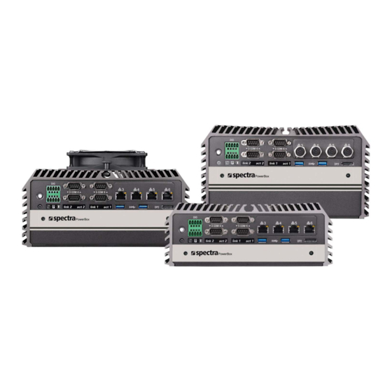
1.3 PRODUCT PICTURES Rear Front Spectra PowerBox 30A0 Spectra PowerBox 31A0 Spectra PowerBox 32A0 1.4 KEY FEATURES • Supports 7/6th‐Gen Intel® Core™ i3 / i5 / i7 Socket‐type CPU (LGA1151) • 2x DDR4 SO‐DIMM Socket, 2,133MHz, Supports Up to 32 GB • Triple Independent Display (DVI‐I, DP, DP/HDMI) • 2x 2.5" SATA HDD/SSD bay (Gen3), Supports RAID 0/1 • PCI/PCIe Slot with Different Combination of Interfaces (For Spectra PowerBox 31Ax & 32Ax only) • 2x CMI Interfaces with 6 Types of Optional Modules for I/O Expansion • 1x CFM Interface for Adding Optional Power Ignition Sensing (IGN) Module • Supports 3x Full‐size Mini‐PCIe Slot for Wireless & I/O Expansion • Wide Operating Temperature (‐40°C to 70°C) • EN50155 / EN50121‐3‐2 Certified for Railway Application • E‐Mark Certified for In‐vehicle Computing Spectra GmbH & Co. KG User Manual Version 2.0 vertrieb@spectra.de Spectra PowerBox 3000A Series September 2018... -
Page 14: Hardware Specification
• 2x DDR4 260-pin SO-DIMM socket, support up to 32 GB • Dimension (WxDxH) / Weight: (2133/2400 MHz, un-buffered and non-ECC type) Spectra PowerBox 30Ax : 227 x 261 x 88 mm, 4.70 kg Graphics Spectra PowerBox 31Ax : 227 x 261 x 108 mm, 5.22 kg •... -
Page 15: System I/O
SIM card, CMOS Battery, and 2.5” Removable HDD Bay Used to inserts a SIM card, CMOS battery, Digital I/O LED Indicates the working status of digital and 2.5” HDD input/ output Spectra PowerBox 30Ax Spectra PowerBox 31Ax Spectra GmbH & Co. KG User Manual Version 2.0 vertrieb@spectra.de... -
Page 16: Rear
Spectra PowerBox 32Ax 1.3.2 Rear DC IN Terminal Block Antenna Hole Used to plug a DC power input with terminal Used to install an antenna jack block COM Port COM 1 ~ COM 2 support RS232/422/485 External Fan Terminal Block... - Page 17 Spectra PowerBox 30Ax Spectra PowerBox 31Ax Spectra PowerBox 32Ax Spectra GmbH & Co. KG User Manual Version 2.0 vertrieb@spectra.de Spectra PowerBox 3000A Series September 2018...
-
Page 18: Mechanical Dimension
1.7 MECHANICAL DIMENSION Unit: mm Spectra PowerBox 30Ax Unit: mm Spectra PowerBox 31Ax Spectra GmbH & Co. KG User Manual Version 2.0 vertrieb@spectra.de Spectra PowerBox 3000A Series September 2018... - Page 19 Unit: mm Spectra PowerBox 32Ax Spectra GmbH & Co. KG User Manual Version 2.0 vertrieb@spectra.de Spectra PowerBox 3000A Series September 2018...
-
Page 20: Chapter 2 Pin Definitions And Settings
Chapter 2 PIN DEFINITIONS AND SETTINGS... -
Page 21: Jumper Settings
3-pin jumpers when they are short (on) and open (off). Three-Pin Jumpers Two-Pin Jumpers 1 2 3 1 2 3 1 2 3 Open Short All pins are open Pins 1 and 2 are short Pins 2 and 3 are short Spectra GmbH & Co. KG User Manual Version 2.0 vertrieb@spectra.de Spectra PowerBox 3000A Series September 2018... -
Page 22: Location Of Jumpers, Switches And Connectors
2.2 LOCATION OF THE CONNECTORS, JUMPERS AND SWITCHES 2.2.1 Top View Spectra GmbH & Co. KG User Manual Version 2.0 vertrieb@spectra.de Spectra PowerBox 3000A Series September 2018... -
Page 23: Bottom View
2.2.2 Bottom View Spectra GmbH & Co. KG User Manual Version 2.0 vertrieb@spectra.de Spectra PowerBox 3000A Series September 2018... -
Page 24: List Of Jumpers, Connectors And Switches
Power Connector MINIPCIE1 Mini PCI-Express Socket + mSATA + 3G Module CN4,5 Mini PCI-Express / mSATA Socket USB11_12_1 Internal USB 2.0 Ports PCIE1 PCI-Express x16 Socket PCIE2 PCI-Express x1 Socket SODIMM1,2 DDR4 SODIMM Socket Spectra GmbH & Co. KG User Manual Version 2.0 vertrieb@spectra.de Spectra PowerBox 3000A Series September 2018... -
Page 25: Definition Of Switches
SATA DOM Function Setting : Pin Define SW1 Switch Switch mode Function SATA DOM Disable (Default) Enable COM1/2 Voltage Function Setting : Pin Define SW1 Switch Switch mode Function 0V(RI) ON/ON (Default) COM1 ON/OFF OFF/OFF 0V(RI) ON/ON (Default) COM2 ON/OFF OFF/OFF Spectra GmbH & Co. KG User Manual Version 2.0 vertrieb@spectra.de Spectra PowerBox 3000A Series September 2018... -
Page 26: Definition Of Connectors
1.5V +3.3VAUX CLKREQ# PERP/SATARN RESERVED SIM_DATA +1.5V REFCLK- SIM_CLK SMB_CLK +1.5V REFCLK+ PETN/SATATN SIM_Reset SMB_DATA PETP/SATATP SIM_VPP +3.3V USB_D- POWER1, POWER2, POWER3, POWER4: Power Connector Connector Type: 1X4-pin Wafer, 2.54mm pitch Definition +12V Spectra GmbH & Co. KG User Manual Version 2.0 vertrieb@spectra.de Spectra PowerBox 3000A Series September 2018... - Page 27 Definition WAKE# 3.3V 3.3V USB_D+ 3.3V PERST# PERN/SATARP 3.3V 1.5V +3.3VAUX PERP/SATARN +1.5V REFCLK- SMB_CLK +1.5V REFCLK+ PETN/SATATN SMB_DATA PETP/SATATP +3.3V USB_D- SATA5: SATA Connector(SATA DOM) Definition Definition RX2- TX2+ RX2+ TX2- NC/+5V Spectra GmbH & Co. KG User Manual Version 2.0 vertrieb@spectra.de Spectra PowerBox 3000A Series September 2018...
- Page 28 GPIO LED LAN LED Status Defines Act LED Status Definition Link LED Status Definition Blinking Yellow Data Activity Steady Green 1Gbps Network Link No Activity Steady Orange 100Mbps Network Link 10Mbps Network Link Spectra GmbH & Co. KG User Manual Version 2.0 vertrieb@spectra.de Spectra PowerBox 3000A Series September 2018...
- Page 29 CN6:Power On/Off, SW Switch +12V Definition SENSE PWR_SW Control COM1_2_1: RS232 / RS422 / RS485 Connector Connector Type: 9-pin D-Sub COM1/COM2 RS422 / 485 RS485 RS232 Full Duplex Half Duplex Definition Definition Definition DATA- DATA+ Spectra GmbH & Co. KG User Manual Version 2.0 vertrieb@spectra.de Spectra PowerBox 3000A Series September 2018...
- Page 30 Description CMI Module with 4x RS-232/422/485 Serial Ports, 8x Optical Isolated DIO PB-3000A-DIO-Modul (4 in/4 out), 1x Spectra PowerBox 30Ax Front Bezel CMI Module with 4x RS-232/422/485 Serial Ports, 8x Optical Isolated DIO PB-3100A-DIO-Modul (4 in/4 out), 1x Spectra PowerBox 31Ax Front Bezel...
- Page 31 +12V 7-9 On 8-10 On (Default) (Default) DTB-COM: RS232 / RS422 / RS485 Connector Connector Type: 9-pin D-Sub COM3/COM4/COM5/COM6 RS422 / 485 RS485 RS232 Full Duplex Half Duplex Definition Definition Definition DATA- DATA+ Spectra GmbH & Co. KG User Manual Version 2.0 vertrieb@spectra.de Spectra PowerBox 3000A Series September 2018...
- Page 32 Description PB-3000A-DIO-ICOM CMI Module with 4x Electrical Isolated RS-232/422/485 Serial Ports, 8x Modul Optical Isolated DIO (4 in/4 out), 1x Spectra PowerBox 30Ax Front Bezel PB-3100A-DIO-ICOM CMI Module with 4x Electrical Isolated RS-232/422/485 Serial Ports, 8x Modul Optical Isolated DIO (4 in/4 out), 1x Spectra PowerBox 31Ax Front Bezel...
- Page 33 Definition DATA- DATA+ Isolated GND Note: COM3/4/5/6 are isolated COM, each pin5 (GND) is independent. DIO1: Digital Input / Output Connector Connector Type: Terminal Block 2X5 10-pin, 3.5mm pitch Definition Definition DC INPUT Spectra GmbH & Co. KG User Manual Version 2.0 vertrieb@spectra.de Spectra PowerBox 3000A Series September 2018...
- Page 34 CMI Module with M12 Connector, 4x PoE+, Intel GbE LAN, Individual PB-3000A-POE-M12-Module Port 25.5W, 1x Universal Bracket PB-3000A-LAN-M12 Connector PB-3000A-LAN-M12 Pin Definitions Connector Type: M12 A coded 8pin connector Definition Definition 2_LAN1_0+ 2_LAN1_0- 2_LAN1_1+ 2_LAN1_2+ 2_LAN1_2- 2_LAN1_1- 2_LAN1_3+ 2_LAN1_3- Spectra GmbH & Co. KG User Manual Version 2.0 vertrieb@spectra.de Spectra PowerBox 3000A Series September 2018...
- Page 35 PB-3000A-PoE-M12 Connector PB-3000A-PoE-M12 Pin Definitions Connector Type: M12 A coded 8pin connector POE type: Midspan (B-Type) Definition Definition 2_LAN1_0+ 2_LAN1_0- 2_LAN1_1+ 2_LAN1_2+(Power PIN) 2_LAN1_2-(Power PIN) 2_LAN1_1- 2_LAN1_3+(Power PIN) 2_LAN1_3-(Power PIN) Spectra GmbH & Co. KG User Manual Version 2.0 vertrieb@spectra.de Spectra PowerBox 3000A Series September 2018...
- Page 36 0 second 1 minute 5 minutes 10 minutes 30 minutes 1 hour 2 hours Reserved (0 second) 12V_24V_1: 12V / 24V Car Battery Switch Definition 24V Car Battery Input 12V Car Battery Input Spectra GmbH & Co. KG User Manual Version 2.0 vertrieb@spectra.de Spectra PowerBox 3000A Series September 2018...
-
Page 37: Chapter 3 System Setup
Chapter 3 SYSTEM SETUP... -
Page 38: Disassembling The System For Installation
1. Turn over the unit to have the bottom side face up, unscrew the 6 screws of bottom cover and place them aside for later use. 2. Remove the bottom cover from the chassis. Spectra GmbH & Co. KG User Manual Version 2.0 vertrieb@spectra.de Spectra PowerBox 3000A Series September 2018... - Page 39 3. Unscrew the 2 screws at rear panel as marked on photo and place them aside for later use. 4. Loosen the 4 screws. Pull out 4 latches as marked on photo. Spectra GmbH & Co. KG User Manual Version 2.0 vertrieb@spectra.de Spectra PowerBox 3000A Series September 2018...
- Page 40 5. Lift up the unit vertically by holding the front and rear panel. 6. Turn over the body of the unit and place it gently. Spectra GmbH & Co. KG User Manual Version 2.0 vertrieb@spectra.de Spectra PowerBox 3000A Series September 2018...
-
Page 41: Installing The Cpu
1. Locate the CPU socket , remove the protection cover on it. 2. Press the CPU socket lever and pull it aside away from the socket to unlock it. Pull back the lever to open the socket. Spectra GmbH & Co. KG User Manual Version 2.0 vertrieb@spectra.de Spectra PowerBox 3000A Series September 2018... - Page 42 3. Align the notches on CPU with the alignment post on socket. 4. The notches of socket provide the space for fingers while lowering the CPU, hold the CPU by the edges toward the notches and insert the CPU gently. Spectra GmbH & Co. KG User Manual Version 2.0 vertrieb@spectra.de Spectra PowerBox 3000A Series September 2018...
- Page 43 5. Place the thermal pad on the CPU heat spreader. Press down the socket lever to lock the CPU. Thermal pad 6. Align mounting holes of heat sink with the nut studs and fasten the heat sink with provided 4 screws. Spectra GmbH & Co. KG User Manual Version 2.0 vertrieb@spectra.de Spectra PowerBox 3000A Series September 2018...
-
Page 44: Installing A Mini-Pcie/Msata Card On Top Side
3.3 INSTALLING A MINI-PCIE/MSATA CARD ON TOP SIDE (APPLICABLE FOR FULL OR HALF SIZE CARD) 1. Locate the Mini PCIe slot on top side of system. Spectra GmbH & Co. KG User Manual Version 2.0 vertrieb@spectra.de Spectra PowerBox 3000A Series September 2018... - Page 45 3. Tilt the Mini PCIe module at a 45 degree angle and insert it to the slot until the gold-pated connector of module contacted firmly with the slot. ° 4. Press down the module and fasten two screws to secure the module. Spectra GmbH & Co. KG User Manual Version 2.0 vertrieb@spectra.de Spectra PowerBox 3000A Series September 2018...
-
Page 46: Installing Antennas
1. Remove the antenna hole covers at rear panel. 2. Have antenna jack penetrate through the hole. 3. Put on washer and fasten the nut with antenna jack. Spectra GmbH & Co. KG User Manual Version 2.0 vertrieb@spectra.de Spectra PowerBox 3000A Series September 2018... - Page 47 4. Assemble the antenna and antenna jack together. 5. Attach the RF connector at another end of cable onto the module. Spectra GmbH & Co. KG User Manual Version 2.0 vertrieb@spectra.de Spectra PowerBox 3000A Series September 2018...
-
Page 48: Installing A Sata Hard Drive On Top Side
2. Make the PCB side of the HDD face up, place the HDD bracket on it. Ensure the direction of bracket is correct and use 4 provided screws to assemble HDD and HDD bracket together. Spectra GmbH & Co. KG User Manual Version 2.0 vertrieb@spectra.de Spectra PowerBox 3000A Series September 2018... - Page 49 3. Turn over the HDD bracket. Connect the HDD bracket to the SATA connector and fasten the 3 screws . Spectra GmbH & Co. KG User Manual Version 2.0 vertrieb@spectra.de Spectra PowerBox 3000A Series September 2018...
-
Page 50: Installing A Low Speed Cmi Module
3.6 INSTALLING A LOW SPEED CMI MODULE The applicable low speed CMI modules for Spectra PowerBox 3000A series are listed in the following table. Model No. Description CMI Module with 4x RS-232/422/485 Serial Ports, 8x Optical Isolated DIO PB-3000A-DIO-Modul (4 in/4 out), 1x Spectra PowerBox 30Ax Front Bezel... - Page 51 2. Locate the connector of CMI-module on top side of system. 3. Insert the CMI module carefully into the CMI connector on main board. Fix it with 4 screws. 4. Fasten the 8 D-Sub jack screws as marked on photo. Spectra GmbH & Co. KG User Manual Version 2.0 vertrieb@spectra.de Spectra PowerBox 3000A Series September 2018...
- Page 52 5. Exchange with the front bezel of low speed CMI module as illustrated. front bezel for CMI-COM module 6. Fasten the 2 hex nuts from the back side of front bezel. Spectra GmbH & Co. KG User Manual Version 2.0 vertrieb@spectra.de Spectra PowerBox 3000A Series September 2018...
-
Page 53: Installing A High Speed Cmi Module
3.7 INSTALLING A HIGH SPEED CMI MODULE The applicable high speed CMI modules for Spectra PowerBox 3000A series are listed in the following table. Model No. Description CMI Module with 4x Intel GbE LAN, RJ45 Port, 1x Universal Bracket PB-3000A-LAN-Module (67 x 15 mm) CMI Module with 4x PoE+, Intel GbE LAN, RJ45 Port, Individual Port 25.5W,... - Page 54 3. Remove the 4 ring nuts from M12 jack before attempting to install the module. 4. (1) Penetrate M12 jack of the module through the I/O hole. (2) Insert the LAN module carefully into the CMI connector on main board as illustrated. Spectra GmbH & Co. KG User Manual Version 2.0 vertrieb@spectra.de Spectra PowerBox 3000A Series September 2018...
- Page 55 5. Fasten 3 screws to fix the module. 6. Attach the M12 I/O bracket, and fasten 2 hex nuts from the back side of the bracket. M12 I/O bracket Spectra GmbH & Co. KG User Manual Version 2.0 vertrieb@spectra.de Spectra PowerBox 3000A Series September 2018...
- Page 56 7.Fasten the 4 ring nuts onto M12 jacks. Spectra GmbH & Co. KG User Manual Version 2.0 vertrieb@spectra.de Spectra PowerBox 3000A Series September 2018...
-
Page 57: Installing A Mini-Pcie/Msata Card At Bottom Side
1. Turn over the body of the unit. Locate Mini-PCIe (mSATA) slots at the bottom. 2. Tilt the Mini-PCIe module at a 45 degree angle and insert it to the slot until the gold-pated connector of module contacted firmly with the slot. 45° Spectra GmbH & Co. KG User Manual Version 2.0 vertrieb@spectra.de Spectra PowerBox 3000A Series September 2018... -
Page 58: Installing So-Dimm Memory
3. Press down the module and use previous two screws to fix the module. 3.9 INSTALLING SO-DIMM MEMORY 1. Locate the SO-DIMM sockets at the bottom side of system. Unscrews the 4 screws and remove the bracket. Spectra GmbH & Co. KG User Manual Version 2.0 vertrieb@spectra.de Spectra PowerBox 3000A Series September 2018... - Page 59 3. Tilt the SO-DIMM module at a 45 degree angle and insert it to SO-DIMM socket until the gold-pated connector of module contacted firmly with the socket. 45° 45° Lower socket Upper socket Spectra GmbH & Co. KG User Manual Version 2.0 vertrieb@spectra.de Spectra PowerBox 3000A Series September 2018...
- Page 60 4. Press the modules down until it’s fixed firmly by the two locking latches on the sides. 5. Put the cover back and fix the cover with 4 screws. Spectra GmbH & Co. KG User Manual Version 2.0 vertrieb@spectra.de Spectra PowerBox 3000A Series September 2018...
-
Page 61: Installing A Cfm-Ign Power Ignition Module
3.10 INSTALLING A CFM-IGN POWER IGNITION MODULE 1. Locate power ignition connector on main board. 2. Insert the power ignition module carefully into the connector on main board. Fasten 2 screws to fix it. Spectra GmbH & Co. KG User Manual Version 2.0 vertrieb@spectra.de Spectra PowerBox 3000A Series September 2018... -
Page 62: Installing The Internal Fan
3.11 INSTALLING THE INTERNAL FAN (For Spectra PowerBox 32Ax ONLY) 1. Unscrew 6 screws to remove 3 I/O brackets from rear panel. 2. Attach the FAN from back side of rear panel. Fasten 4 screws to fix it. Spectra GmbH & Co. KG User Manual Version 2.0... - Page 63 3. Connect the FAN power cable to the power connector on main board.as marked on photo. Spectra GmbH & Co. KG User Manual Version 2.0 vertrieb@spectra.de Spectra PowerBox 3000A Series September 2018...
-
Page 64: Installing A Pci/Pcie Add-On Card
3.12 INSTALLING A PCI/PCIE ADD-ON CARD (For Spectra PowerBox 31Ax & 32Ax ONLY) The applicable riser cards for Spectra PowerBox 3000A series are listed in the following table. Model No. Description RSC-E16 Riser Card 1 x PCIex16 RSC-P Riser Card 1 x PCI... - Page 65 1. Unscrew the 4 screws to remove the extension bracket. 2. Remove the extension bracket from the system. Spectra GmbH & Co. KG User Manual Version 2.0 vertrieb@spectra.de Spectra PowerBox 3000A Series September 2018...
- Page 66 3. Assemble the riser card with extension bracket together and fasten with the 4 screws. Extension Bracket 4. (1) Loosen the screw to remove I/O bracket. (2) Loosen the 2 screws halfway to allow the card retainer to be adjustable. Spectra GmbH & Co. KG User Manual Version 2.0 vertrieb@spectra.de Spectra PowerBox 3000A Series September 2018...
- Page 67 5. (1) Insert a PCI(e) add-on card to the slot. (2) Fasten the screw to secure it (3) Push the card retainer forward to against the edge of the add-on card. (4) Tighten the screw to fix the card retainer. 6. Locate the riser card slot on bottom side of system. Spectra GmbH & Co. KG User Manual Version 2.0 vertrieb@spectra.de Spectra PowerBox 3000A Series September 2018...
-
Page 68: Assembling The System
7. Install the module assembled in step 4 into the riser card slot, and fasten the 4 screws to secure it. 3.13 ASSEMBLING THE SYSTEM 1. Make sure the notch on chassis and the front bezel of body are at the same side. Spectra GmbH & Co. KG User Manual Version 2.0 vertrieb@spectra.de Spectra PowerBox 3000A Series September 2018... - Page 69 2. Lift up the body of unit. Make sure that both front and rear panels are in the chassis groves and assemble the body on to chassis firmly. 3. Push into the 4 latches as indicated and fasten the 4 screws. Spectra GmbH & Co. KG User Manual Version 2.0 vertrieb@spectra.de Spectra PowerBox 3000A Series September 2018...
- Page 70 4. Fasten the 2 screws at rear panel. 5. Be sure to align the grooves with front and ear panels. Put the cover back on and fasten the 6 screws to fix the cover. Spectra GmbH & Co. KG User Manual Version 2.0 vertrieb@spectra.de Spectra PowerBox 3000A Series September 2018...
-
Page 71: Installing A Sata Hard Drive At Front Side
3.14 INSTALLING A SATA HARD DRIVE AT FRONT SIDE 1. Loosen the screws in order to remove the front expansion plate. 2. Locate the removable HDD bay and loosen the screw. Spectra GmbH & Co. KG User Manual Version 2.0 vertrieb@spectra.de Spectra PowerBox 3000A Series September 2018... - Page 72 4. Make the PCB side of the HDD face up, place the HDD bracket into it. Ensure the direction of bracket is correct and use 4 provided screws to assemble HDD and HDD bracket together. Spectra GmbH & Co. KG User Manual Version 2.0 vertrieb@spectra.de Spectra PowerBox 3000A Series September 2018...
- Page 73 5. Align the HDD bracket with the entrance of HDD bay. Holding the rotating arm and insert the HDD bracket until the connector of HDD contact the SATA connector firmly. 6. Place the rotating arm back and fasten the screw. Spectra GmbH & Co. KG User Manual Version 2.0 vertrieb@spectra.de Spectra PowerBox 3000A Series September 2018...
-
Page 74: Installing A Sim Card
3.15 INSTALLING A SIM CARD 1. Locate SIM card slot on top of HDD bay. 2. Insert the SIM card according to the icon instruction aside. Spectra GmbH & Co. KG User Manual Version 2.0 vertrieb@spectra.de Spectra PowerBox 3000A Series September 2018... -
Page 75: Installing The Cmos Battery
3.16 INSTALLING THE CMOS BATTERY 1. Locate the removable CMOS Battery and loosen the screw. 2. Pull out the CMOS battery bracket with assistance of a tweezer. Spectra GmbH & Co. KG User Manual Version 2.0 vertrieb@spectra.de Spectra PowerBox 3000A Series September 2018... - Page 76 3. Insert a CMOS battery in the battery slot. 4. Insert the battery bracket firmly and fasten the screw. Spectra GmbH & Co. KG User Manual Version 2.0 vertrieb@spectra.de Spectra PowerBox 3000A Series September 2018...
-
Page 77: Fasten The Cover
3.17 FASTEN THE COVER 1. Fasten the cover by using the two screws. 3.18 INSTALL AN EXTERNAL FAN 1. Prepare an external fan. Loosen the 2 screws halfway on mounting frame before attempting to install it. Spectra GmbH & Co. KG User Manual Version 2.0 vertrieb@spectra.de Spectra PowerBox 3000A Series September 2018... - Page 78 2. Slide the FAN into the middle groove of chassis as illustrated. Tighten the 2 screws to fix it onto chassis. 3. Move the fan to the center of chassis. Tighten the 2 screws marked on photo to secure it. Spectra GmbH & Co. KG User Manual Version 2.0 vertrieb@spectra.de Spectra PowerBox 3000A Series September 2018...
- Page 79 4. Connect the FAN cable to external fan power connector at rear panel. Spectra GmbH & Co. KG User Manual Version 2.0 vertrieb@spectra.de Spectra PowerBox 3000A Series September 2018...
-
Page 80: Wall Mount Brackets
3.22 WALL MOUNT BRACKETS The Spectra PowerBox 3000A series offers wall mount that customers can install system on the wall in convenient and economical ways. 1. The mounting holes are at the bottom of system. Use provided 8 screws to fasten the bracket with each side of system together. - Page 81 2. Fasten the screws through the bracket mounting hole to mount system on the wall. Spectra GmbH & Co. KG User Manual Version 2.0 vertrieb@spectra.de Spectra PowerBox 3000A Series September 2018...
-
Page 82: Chapter 4 Bios Setup
Chapter 4 BIOS SETUP... -
Page 83: Bios Introduction
( ↑↓ ) to highlight the field and press <Enter> to call up the sub-menu. Then you can use the control keys to enter values and move from field to field within a sub-menu. If you want to return to the main menu, just press the <Esc >. Spectra GmbH & Co. KG User Manual Version 2.0 vertrieb@spectra.de Spectra PowerBox 3000A Series September 2018... -
Page 84: Main Setup
Enables or disables display detailed system hardware information. 4.2.2 System Date Set the date. Please use <Tab> to switch between date elements. 4.2.3 System Time Set the time. Please use <Tab> to switch between time elements. Spectra GmbH & Co. KG User Manual Version 2.0 vertrieb@spectra.de Spectra PowerBox 3000A Series September 2018... -
Page 85: Advanced Setup
4.3 ADVANCED SETUP This section allows you to configure and improve your system and allows you to set up some system features according to your preference. 4.3.1 ACPI Settings Spectra GmbH & Co. KG User Manual Version 2.0 vertrieb@spectra.de Spectra PowerBox 3000A Series September 2018... -
Page 86: Amt Configuration
Enable or disable S3 Video Repost. ■ ACPI Low Power S0 Idle [Disabled] Enables or disables ACPI Low Power S0 idle support. 4.3.2 AMT Configuration ■ Intel AMT [Enabled] Enables or disables Intel® Active Management Technology BIOS Extension. Spectra GmbH & Co. KG User Manual Version 2.0 vertrieb@spectra.de Spectra PowerBox 3000A Series September 2018... -
Page 87: Pch-Fw Configuration
■ Un-Configure ME [Disabled] Enables or disables Un-Configure-Management Engine(ME) without password. 4.3.3 PCH-FW Configuration ■ Firmware Update Configuration Configure Management Engine Parameters Me FW Image Re-Flash [Disabled] Enables or disables Me FW Image Re-Flash function. Spectra GmbH & Co. KG User Manual Version 2.0 vertrieb@spectra.de Spectra PowerBox 3000A Series September 2018... -
Page 88: F81866 Super Io Configuration
4.3.4 F81866 Super IO Configuration Set Parameters of Serial Ports. User can Enable/Disable the serial port and Select an optimal settings for the Super IO Device ■ Serial Port 1~6 Configuration. Spectra GmbH & Co. KG User Manual Version 2.0 vertrieb@spectra.de Spectra PowerBox 3000A Series September 2018... -
Page 89: Hardware Monitor
User can set a value in the range of 0 to 255. 4.3.5 Hardware Monitor These items display the current status of all monitored hardware devices/components such as voltages, temperatures and all fans’ speeds. Spectra GmbH & Co. KG User Manual Version 2.0 vertrieb@spectra.de Spectra PowerBox 3000A Series September 2018... -
Page 90: S5 Rtc Wake Settings
Enables or disables wake system from S5 (soft-off state). [Disabled]: Disables this function. [Fixed Time]: Sets a specified time (HH:MM:SS) to wake system from S5. [Dynamic Time]: Sets a increase minute(s) from current time to wake system from Spectra GmbH & Co. KG User Manual Version 2.0 vertrieb@spectra.de Spectra PowerBox 3000A Series September 2018... -
Page 91: Serial Port Console Redirection
4.3.7 Serial Port Console Redirection ■ Console Redirection [Disabled] These items allow users to enable or disable COM0, COM1, COM2, COM3, COM4, COM5 console redirection function. 4.3.8 CPU Configuration Spectra GmbH & Co. KG User Manual Version 2.0 vertrieb@spectra.de Spectra PowerBox 3000A Series September 2018... -
Page 92: Sata Configuration
4.3.9 SATA Configuration ■ SATA Controller(s) [Enabled] Enables or disables SATA device. ■ SATA Mode Selection [AHCI] Allows you to select which mode SATA controller will operates. Configuration options: [AHCI], [RAID] Spectra GmbH & Co. KG User Manual Version 2.0 vertrieb@spectra.de Spectra PowerBox 3000A Series September 2018... - Page 93 LED Locate [Enabled] Enables or disables LED Locate. Smart Response Technology [Enabled] Enables or disables Smart Response Technology. RST Force Form [Disabled] Enables or disables RST(Intel® Storage Technology) Force Form. Spectra GmbH & Co. KG User Manual Version 2.0 vertrieb@spectra.de Spectra PowerBox 3000A Series September 2018...
-
Page 94: Pci Subsystem Settings
Enables or disables SATA Port 3. ■ Serial ATA Port 4 Port 4 [Enabled] Enables or disables SATA Port 4. ■ Serial ATA Port 5 Port 5 [Enabled] Enables or disables SATA Port 5. 4.3.10 PCI Subsystem Settings Spectra GmbH & Co. KG User Manual Version 2.0 vertrieb@spectra.de Spectra PowerBox 3000A Series September 2018... - Page 95 Enables or disables 64bit capable devices to be decoded in above 4G address space. ■ Don’t Reset VC-TC Mapping [Disabled] Enables or disables software can reset traffic class mapping through virtual channels if system has virtual channels. ■ PCI Hot-Plug Settings Spectra GmbH & Co. KG User Manual Version 2.0 vertrieb@spectra.de Spectra PowerBox 3000A Series September 2018...
-
Page 96: Csm Configuration
Configuration options; [Disabled] [1M] [2M] [4M] [8M] [16M] [32M] [64M] [128M] ■ PFMMIO 32 bit Resources Padding [16M] Allows users to set I/O Resources Padding. Configuration options; [Disabled] [1M] [2M] [4M] [8M] [16M] [32M] [64M] [128M] 4.3.11 CSM Configuration Spectra GmbH & Co. KG User Manual Version 2.0 vertrieb@spectra.de Spectra PowerBox 3000A Series September 2018... - Page 97 [UEFI]: Enables UEFI option ROM only. [Legacy]: Enables legacy option ROM only. ■ Other PCI devices [UEFI] Allows users to determine option ROM execution policy for devise other than network, storage, or video. Spectra GmbH & Co. KG User Manual Version 2.0 vertrieb@spectra.de Spectra PowerBox 3000A Series September 2018...
-
Page 98: Usb Configuration
Enables or disables XHCI (USB3.0) hand-off function. Use this feature as a workaround for operating systems without XHCI hand-off support. ■ USB Mass Storage Driver Support [Enabled] Enables or disables USB mass storage driver support. Spectra GmbH & Co. KG User Manual Version 2.0 vertrieb@spectra.de Spectra PowerBox 3000A Series September 2018... -
Page 99: Chipset Setup
4.4 CHIPSET SETUP This section allows you to configure chipset related settings according to user’s preference. 4.4.1 System Agent (SA) Configuration Spectra GmbH & Co. KG User Manual Version 2.0 vertrieb@spectra.de Spectra PowerBox 3000A Series September 2018... -
Page 100: Pch-Io Configuration
Configuration options: [Auto] [IGFX] [PEG] [PCIE] Internal Graphics [Auto] Allows users to enable or disable Internal Graphics. Configuration options: [Auto] [Disabled] [Enabled] ■ Memory Configuration This item displays detailed memory information in the system. 4.4.2 PCH-IO Configuration Spectra GmbH & Co. KG User Manual Version 2.0 vertrieb@spectra.de Spectra PowerBox 3000A Series September 2018... - Page 101 PCI Express Root Port 4 [Enabled] Enables or disables PCI Express Root Port 4. Configuration options: [Auto] [Gen1] [Gen2] [Gen3]. ■ HD Audio Configuration HD Audio [Auto] Control detection of the HD-Audio device. Configuration options: [Disabled]:[Enabled] [Auto] Spectra GmbH & Co. KG User Manual Version 2.0 vertrieb@spectra.de Spectra PowerBox 3000A Series September 2018...
- Page 102 Allows you to switch to Mini PCIe or mSATA interface for CN5 slot. ■ Amplifier Function [Enabled] Enables or disables Amplifier Function. ■ Power Over Ethernet Function [Enabled] Enables or disables Power Over Ethernet Function. Spectra GmbH & Co. KG User Manual Version 2.0 vertrieb@spectra.de Spectra PowerBox 3000A Series September 2018...
-
Page 103: Security Setup
Allows you to set Administrator Password to control access to the BIOS Setup utility. 4.5.2 User Password Allows you to set User Password to control access to the system at boot and to the BIOS Setup utility. Spectra GmbH & Co. KG User Manual Version 2.0 vertrieb@spectra.de Spectra PowerBox 3000A Series September 2018... -
Page 104: Boot Setup
4.6.5 New Boot Option Policy [Default] Allows you to change New Boot Option Policy. Configuration options: [Default] [Place First] [Place Last]. Spectra GmbH & Co. KG User Manual Version 2.0 vertrieb@spectra.de Spectra PowerBox 3000A Series September 2018... -
Page 105: Save & Exit
4.7.8 Save as User Defaults This item allows you to save the changes done so far as user defaults. 4.7.9 Restore User Defaults This item allows you to restore the user defaults to all the setup options. Spectra GmbH & Co. KG User Manual Version 2.0 vertrieb@spectra.de Spectra PowerBox 3000A Series September 2018... -
Page 106: Chapter 5 Product Application
Chapter 5 PRODUCT APPLICATION (FOR CMI-CD, CMI-ICD ONLY) -
Page 107: Digital I/O (Dio) Application
To disable configuration, write exit entry key 0xAA to the index port. Following is an example to enable configuration and disable configuration by using debug. -o 4e 87 -o 4e 87 (enable configuration) -o 4e aa (disable configuration) Spectra GmbH & Co. KG User Manual Version 1.1 vertrieb@spectra.de Spectra PowerBox 3000A Series September 2018... - Page 108 5.1.1.3 Relative Registers To program the F81866A configuration registers, the following configuration procedures. Spectra GmbH & Co. KG User Manual Version 1.1 vertrieb@spectra.de Spectra PowerBox 3000A Series September 2018...
- Page 109 //Set (bit 4~7) = 0 to select GP 74~77 as Input mode. <input Value> WriteByte(AddrPort, 0x82) // Select configuration register 82h ReadByte(DataPort, Value) // Read bit 4~7(0xFx)= GP74 ~77 as High. <Leave the Extended Function Mode> WriteByte(AddrPort, 0xAA) Spectra GmbH & Co. KG User Manual Version 1.1 vertrieb@spectra.de Spectra PowerBox 3000A Series September 2018...
- Page 110 // Select configuration register 60h (High Byte address) WriteByte(DataPort, ( 0x0A)) WriteByte(AddrPort, 0x61) // Select configuration register 61h (Low Byte address) WriteByte(DataPort, ( 0x00)) <Leave the Extended Function Mode> WriteByte(AddrPort, 0xAA) Default DIO Port base address is set to 0x0A00h Spectra GmbH & Co. KG User Manual Version 1.1 vertrieb@spectra.de Spectra PowerBox 3000A Series September 2018...
- Page 111 ‐ ‐ ‐ ‐ 0 1 0 0 value (Base address +2) (0xA02) 7 6 5 4 3 2 1 0 = DO4 ‐ ‐ ‐ ‐ 1 0 0 0 value (Base address +2) (0xA02) Spectra GmbH & Co. KG User Manual Version 1.1 vertrieb@spectra.de Spectra PowerBox 3000A Series September 2018...
-
Page 112: Cmi-Cd, Cmi-Icd Digital I/O (Dio) Hardware Specification
- Logic 1: Open • Input Voltage: - Logic 0: -3V (Min/D1 to COM+) • 4x Digital Output (Open Drain) - Supply Voltage: 5~48V - Sink Current: 1A (Max) - DIO Max: 48V Spectra GmbH & Co. KG User Manual Version 1.1 vertrieb@spectra.de Spectra PowerBox 3000A Series September 2018... -
Page 113: Cmi-Cd, Cmi-Icd Connector Definitions
5.2.1 CMI-CD, CMI-ICD Connector Definition DIO1: Digital Input / Output Connector Connector Type: Terminal Block 2X5 10-pin, 3.5mm pitch Definition Definition DC INPUT Spectra GmbH & Co. KG User Manual Version 1.1 vertrieb@spectra.de Spectra PowerBox 3000A Series September 2018... - Page 114 Spectra GmbH & Co. KG Spectra GmbH & Co. KG Spectra (Schweiz) AG Mahdenstr. 3 Gewerbepark Ost 1 Flugplatzstr. 5 72768 Reutlingen 4621 Sipbachzell (Wels) 8404 Winterthur Germany Austria Switzerland Phone Phone +49 (0) 7121 1432-10 +43 (0) 7240 20190...
Need help?
Do you have a question about the POWERBOX PB-3000A-IGN and is the answer not in the manual?
Questions and answers